SODIUM BOROHYDRIDE (NABH4) AS A HIGH-CAPACITY MATERIAL FOR NEXT-GENERATION SODIUM-ION CAPACITORS
←
→
Page content transcription
If your browser does not render page correctly, please read the page content below
Open Chemistry 2021; 19: 432–441
Research Article
Pawel Jeżowski*, Olivier Crosnier, Thierry Brousse
Sodium borohydride (NaBH4) as a high-capacity
material for next-generation sodium-ion
capacitors
https://doi.org/10.1515/chem-2021-0040
received December 1, 2020; accepted March 8, 2021
1 Introduction
Abstract: Energy storage is an integral part of the modern In the recent years, the topic of hybrid energy storage
world. One of the newest and most interesting concepts devices categorized as metal-ion capacitors (MICs) has
is the internal hybridization achieved in metal-ion capa- been receiving the attention of scientists due to their
citors. In this study, for the first time we used sodium high energy and power output [1–4]. MICs are constructed
borohydride (NaBH4) as a sacrificial material for the pre- of a positive electrode, most often activated carbon (AC),
paration of next-generation sodium-ion capacitors (NICs). which stores energy in the electrical double layer [5,6]. On
NaBH4 is a material with large irreversible capacity of ca. the other side, the faradaic-negative electrode undergoes a
700 mA h g−1 at very low extraction potential close to 2.4 reversible redox reaction of metal ions [7,8]. The biggest
vs Na+/Na0. An assembled NIC cell with the composite- flaw of MICs is the necessary pre-insertion step of the
positive electrode (activated carbon/NaBH4) and hard negative electrode to form a fully functioning MIC. The
carbon as the negative one operates in the voltage range biggest record of pre-insertion topics is related to the
from 2.2 to 3.8 V for 5,000 cycles and retains 92% of its lithium-based devices called lithium-ion capacitors
initial capacitance. The presented NIC has good efficiency (LICs), where three techniques are used to this day:
>98% and energy density of ca. 18 W h kg−1 at power
(1) Use of metallic lithium:
2 kW kg−1 which is more than the energy (7 W h kg−1 The first method has two variations:
at 2 kW kg−1) of an electrical double-layer capacitor (EDLC) • Pre-insertion with metallic lithium can be done in
operating at voltage 2.7 V with the equivalent components two steps. First, the negative electrode undergoes a
as in NIC. Tin phosphide (Sn4P3) as a negative electrode metal-ion intercalation in a cell with a metallic
allowed the reaching of higher values of the specific energy
lithium as a second electrode. Second, the pre-
density 33 W h kg−1 (ca. four times higher than EDLC) at the
lithiated-negative electrode is shifted to a second
power density of 2 kW kg−1, with only 1% of capacity loss
cell with an AC-positive electrode to form an opera-
upon 5,000 cycles and efficiency >99%.
tional LIC [9]. All manipulations are carried out
Keywords: sodium-ion capacitors, sacrificial salt, sodium under an inert atmosphere to limit the exposure
inorganic salt, pre-sodiation, composite carbon electrode of cell elements to O2 or H2O, which greatly
increases the cost [10].
• One-step assembly can be achieved if an auxiliary
lithium electrode is added during the cell construc-
tion. The graphite electrode is connected externally
* Corresponding author: Pawel Jeżowski, Université de Nantes,
versus the metallic lithium electrode and once the
CNRS, Institut des Matériaux Jean Rouxel, IMN, F-44000 Nantes,
France; Réseau sur le Stockage Electrochimique de l’Energie (RS2E),
pre-lithiation is finished, the connection is then
CNRS FR 3459, 33 rue Saint Leu, 80039 Amiens, Cedex, France; swapped to graphite intercalation compound versus
Poznan University of Technology, Institute of Chemistry and AC electrode [11,12]. There are two problems with
Technical Electrochemistry, Berdychowo 4, 60-965, Poznań, Poland, this approach, the first being that the construction
e-mail: pawel.jezowski@put.poznan.pl
of the cell is very complex.
Olivier Crosnier, Thierry Brousse: Université de Nantes, CNRS,
Institut des Matériaux Jean Rouxel, IMN, F-44000 Nantes, France;
However, the biggest flaw of a metallic electrode
Réseau sur le Stockage Electrochimique de l’Energie (RS2E), used is the dendrite formation on its surface which can
CNRS FR 3459, 33 rue Saint Leu, 80039 Amiens, Cedex, France lead to cell short circuiting and thermal runaway [13–15].
Open Access. © 2021 Pawel Jeżowski et al., published by De Gruyter. This work is licensed under the Creative Commons Attribution 4.0
International License.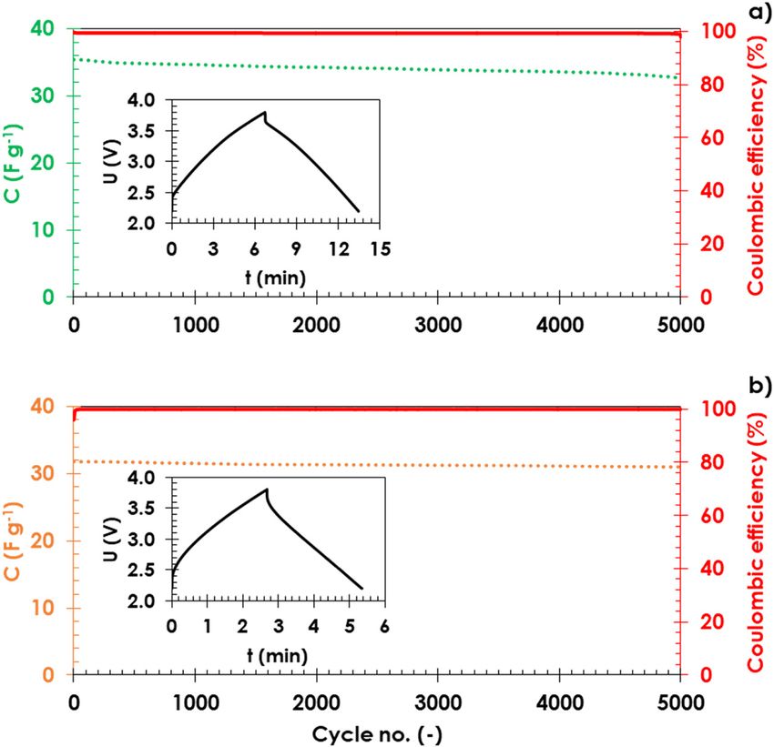
NaBH4 – a high-capacity material for next-generation sodium-ion capacitors 433
(2) Use of lithium ions in the electrolyte fully extracted from Na2S, the positive electrode contains
The second method incorporates in the cell con- electrochemically inactive by-products such as polysul-
struction a high-concentration lithium-ion electro- phides [39] from Na2S oxidation. As this “dead mass”
lyte. However, the electrolyte conductivity decreases stays in the positive electrode, it can cause a reduction
once the pre-insertion step is complete, which is con- in the specific energy. Hence, it is necessary to search for
sidered an enormous drawback leading to worse materials which, after oxidation, would be liberated from
electrochemical performance and shorter cyclability the electrode material in gaseous form similar to the case
of the cell [16]. of sodium amide.
(3) Use of sacrificial material: In the search of such properties, sodium borohydride
The third proposed method allows the assembly (NaBH4) with a theoretical capacity of 670 mA h g−1 and
of LICs in one step, by using a sacrificial lithium possible formation gaseous by-products after oxidation
source and AC in the form of a composite-positive seems to be a promising candidate for realizing the
electrode [17–22]. Lithium ions can be irreversibly next-generation NICs with no dead mass. The results pre-
extracted from the structure of the sacrificial material sented in this study confirms that all NaBH4 is irreversibly
during initial oxidation. Extracted metal ions allow extracted, while the BH−4 anion is electrochemically oxi-
the concentration of lithium ions to stay at a constant dized and can be removed from the cell while not
value during the formation of the solid electrolyte decreasing the specific energy and power of the NIC cell.
interphase (SEI) and the intercalation of the negative
electrode. The oxidized form of the sacrificial mate-
rial after lithium ions are extracted can remain as
electrochemically inactive “dead mass” in the com- 2 Methods and materials
posite-positive electrode [17,18] or can dissolve in the
electrolyte [19]. The sacrificial material should fulfil 2.1 Positive electrode preparation for NIC
one of the two main conditions: (1) a high irreversible
capacity to reduce its amount in the positive elec- In a glove box with less than 0.1 ppm of H2O and O2,
trode and (2) a low extraction potential to avoid elec- 0.55 g of AC (Kuraray YP 80 F) and 0.25 g of NaBH4
trolyte oxidation [17–22]. (Sigma Aldrich, 99.99%) were added to a round-bottom
Lithium-based systems are expensive as lithium is flask with 20 mL of n-heptane (anhydrous, ≥99%; Merck).
one of the rarest elements on the Earth and its ores are The mixture was stirred using a magnetic stirrer.
located in geopolitically unstable regions. This is why we Under the fume hood, 0.08 g of a 60% solution of
should lean towards the use of sodium and sodium-ion binder polytetrafluoroethylene (PTFE, 60% dispersion
capacitors (NICs), which are starting to be promising in water; Merck) and 0.15 g of carbon black (Super C65,
energy storage devices [10]. The abundance of sodium Imerys) were mixed in a beaker with 20 mL of ethanol
is almost four orders of magnitude higher than lithium. using a magnetic stirrer at a rotational speed of 500 rpm
Sodium ores are evenly distributed across the globe and and temperature of 90°C until the solvent is completely
are easily accessible in politically stable regions [23]. The evaporated. The beaker was afterwards transferred to a
most important advantages are (i) sodium does not form vacuum oven at 120°C with continuous vacuum for 12 h to
alloys with aluminium near the insertion potential, (ii) it remove any residues of the solvent. The dried mixture in a
is cheaper, and (iii) it is lighter than copper and could replace beaker was then transferred to the glove box.
it in the near future [10]. The earliest work mentioning Once the dried mixture (PTFE and C65) was inside the
NIC is from 2012 by Kuratani et al. [24]. The mentioned glove box, it was added to a beaker with AC, NaBH4, and
work used a pre-sodiated hard carbon (HC)-negative 20 mL of n-heptane and mixed with a magnetic stirrer.
electrode and an AC-positive electrode soaked in electro- The mixture was stirred until the excess solvent is eva-
lyte; 1 mol L−1 NaPF6 dissolved in ethylene carbonate porated and formation of dough-like matter from which a
(EC)/diethyl carbonate (DEC). Currently, the majority of homogenous sheet of electrode material was formed (its
the published studies present the use of a metallic sodium thickness was about 140 μm). Electrodes with 16 mm dia-
as a source of sodium ions for the pre-sodiation step meter were cut with hollow punchers, then placed in a
to form a functional NIC [25–36]. Until now, there are vial, dried in a glass oven B-585 vacuum drier at 120°C
only a few recent works that show the possible use of for 12 h, and then moved back to the glove box without
a sacrificial material; sodium sulphide (Na2S) [37] or contact with water or oxygen (to avoid any traces of
sodium amide (NaNH2) [38]. However, once sodium is moisture). Final composition of the composite-positive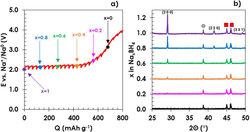
434 Pawel Jeżowski et al.
electrode was 55 wt% of AC, 25 wt% of NaBH4, 15 wt% of 0.08 g (PTFE, 60% dispersion in water, Sigma Aldrich)
carbon black, and 5 wt% of PTFE. Mass of the electrode and soot; 0.15 g (Super C65, Imerys) was mixed in a beaker
disk was about 7 mg cm−2. For the experiments with tin with 20 mL of ethanol. The EDLC electrodes’ final compo-
phosphide, a negative electrode an additional batch of sition was 80 wt% of AC, 15 wt% of soot, and 5 wt% of
positive composite electrodes was prepared (their thick- binder. The mass loading of the electrode material was
ness was ca. 110 μm) and their composition was 45 wt% of approximately 5 mg cm−2.
AC, 35 wt% of NaBH4, 15 wt% of carbon black, and 5 wt%
of PTFE; and in this case, the mass of electrode disk was
near 6 mg cm−2.
2.4 Electrochemical investigation
All cells were assembled in an argon-filled glove box.
2.2 Negative electrode preparation for NIC For sodium extraction investigations, two-electrode cells
were used (El-Cell, Germany). The cell was composed of a
The HC (Kureha grade, PJ, Japan) or tin phosphide (Sn4P3; working electrode (NaBH4/AC) and a counter/reference
referred to this article as SnP) was used for the preparation electrode (sodium disk of thickness ca. 250 μm). Both
of two separate batches of negative electrodes. HC elec- electrodes were separated from each other by a 670-μm
trodes were prepared by mixing 0.91 g of HC (Kureha PJ), thick GF/D Whatman membrane (diameter 18 mm), which
1.6 g of PVDF solution dispersed in 1-methyl-2-pyrrolidi- was soaked with 450 μL of electrolyte 1 mol L−1 solution of
none (using a 5 wt% PVDF solution in NMP; 99.5% anhy- sodium perchlorate (NaClO4; Sigma Aldrich, >98%) dis-
drous, Sigma Aldrich), and 0.01 g of Super C65 with solved in a mixture of EC and propylene carbonate (EC:PC,
a homogenizer at 15,000 rpm for 15 min. An additional volumetric ratio 1:1, referred to as electrolyte throughout
amount of 1 mL of NMP was introduced while mixing to this study). The electrochemical process of sodium extrac-
decrease the ink viscosity. The final composition of the tion from the NaBH4/AC electrode was studied by cyclic
HC-negative electrode was 91 wt% of HC, 8 wt% of binder, voltammetry (CV) and galvanostatic charge/discharge
and 1 wt% of soot. Then, the ink was laid out on alumi- with potential limitation (GCPL). In the case of CVs, the
nium foil (thickness 35 μm) by an automatic film appli- electrode potential was scanned from open circuit poten-
cator (thickness of the ink was set to be about 100 μm). tial (OCP) to 4.0 V and backward to 2.0 V Na+/Na0 at a
NMP was evacuated from the coating by heating it to sweeping rate of 0.06 mV s−1. GCPL on the Na2BCN/AC
100°C under a fume hood and further under vacuum at composite-positive electrode was done at C/20 (where
120°C for 12 h. After drying, the coated foil was calendered C corresponds to the theoretical capacity of NaBH4,
with a laboratory roll press heated up to 70°C until 670 mA h g−1), and the potential range was the same as
reaching a thickness of approximately 90 μm, to improve for the CV investigation.
the electrode material density and have contact with the A similar procedure was used for the investigation of
current collector. Electrodes with a diameter of 16 mm negative electrode materials for NIC cells: HC or SnP. To
were punched out from the calendered electrode sheet establish the practical capacity of the HC electrode, the
using a precision disc cutter. The mass loading of the electrochemical reaction between sodium ions and HC
HC electrode material was approximately 6 mg cm−2. The electrode was performed by GCPL at a current density of
Sn4P3 and the electrodes were prepared according to 20 mA g−1, starting from OCP until reaching a potential lim-
the detailed description reported elsewhere [36]. The itation of 5 mV vs Na0/Na+ (for HC) or 100 mV vs Na+/Na0
mass loading of the electrode material was approxi- (for SnP) after which the sodium ions were deinserted until
mately 3 mg cm−2. reaching 2.0 V vs Na+/Na0. The estimated initial capacity of
the HC was ca. 300 mA h g−1 and SnP ca. 650 mA h g−1.
The change in pressure during the electrochemical
2.3 Preparation of electrodes for electrical oxidation of NaBH4 sacrificial was observed in ECC-
double-layer capacitor (EDLC) Press-Air-DL (El-Cell).
The in situ X-ray diffraction (XRD) experiment was
To compare the energy and power densities under similar performed in the same cell and using the analogical
conditions, an EDLC cell was assembled with two AC methodology as described elsewhere [18].
electrodes prepared in ambient conditions. A mixture The NICs were formed in a three-electrode cell from
consisting of AC; 0.80 g (Kuraray YP80F), binder solution; El-Cell. Positive (NaBH4/AC) and negative electrodes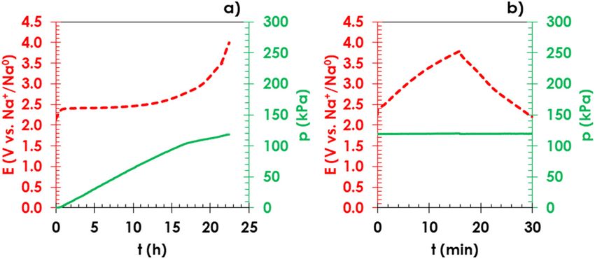
NaBH4 – a high-capacity material for next-generation sodium-ion capacitors 435
(HC or SnP) were separated by a porous membrane (El- Ethical approval: The conducted research is not related to
Cell, thickness 1,550 μm) and soaked with electrolyte. either human or animal use.
A sodium pin was used as the reference electrode to
monitor the potential of both electrodes. The reference
electrode had only direct contact with the separator and
was located at the same distance from the positive and 3 Results and discussion
negative electrodes. Mass ratio between AC and negative
electrode active material was 1:1. The irreversibility of sodium extraction from NaBH4 was
Pre-sodiation of the negative electrodes was achieved analysed in a cell with a metallic sodium counter/refer-
by GCPL at C/20 rate, starting from OCP until reaching a ence electrode by cyclic voltamperometry and galvano-
potential limitation for the positive electrode (4.0 V vs static charge/discharge. The initial CV cycle (Figure 1a)
Na+/Na0) or 5 mV vs Na+/Na0 for HC and 100 mV for shows an increase in anodic current corresponding to the
SnP vs Na+/Na0-negative electrode. After pre-sodiation, sodium extraction process, and it starts to rise near 2.4 V
the NIC cells were conditioned for a total number of 300 vs Na+/Na0 and presents a maximum near 2.7 V vs Na+/
cycles. Once the the cells are conditioned, the NIC cells Na0. However, during the cathodic sweep, no current
were cycled for 5,000 cycles at one value of current den- response was observed, which means that the sodium
sity (125 mA g−1 for NIC cells with HC-negative electrode extraction process is irreversible. Moreover, the following
and 250 mA g−1 for NIC with SnP-negative electrode). cycle (black solid line) displays a capacitive behaviour of
The EDLCs were assembled in two-electrode El-Cell AC, which is a major part of the composite electrode
cells. Positive and negative electrodes were composed of (Figure 1a). The galvanostatic charge/discharge at C/20
AC used in NIC cells and they had similar masses. Both (where C corresponds to the theoretical capacity of NaBH4,
electrodes were separated by a porous membrane (GF/D, 710 mA h g−1) in the potential range from 2.0 to 4.0 V vs
Whatman, thickness 670 μm) soaked with 450 μL of elec- Na+/Na0 (Figure 1b) shows a well-visible oxidation plateau
trolyte. The EDLC cells were conditioned by 300 cycles of at about 2.4 V vs Na+/Na0, and the absence of a plateau
CVs in the voltage range from 0.0 to 2.7 V at scanning rate of during negative polarization again confirms the irrever-
5 mV s−1. The specific energy of the cell was determined by sible character of the process. The practical irreversible
the constant power method for both systems to avoid over- capacity of sodium extraction is close to 700 mA h g−1.
estimation of achievable values in the case of EDLCs [40]. To confirm that the NaBH4 is removed from the com-
The electrochemical tests were done with a multi- position of the positive electrode, we performed sepa-
channel potentiostat/galvanostat with impedance chan- rately two experiments: the in situ XRD (Figure 2a and b)
nels (VMP3, Biologic), and the data were collected by and the in operando observation of pressure change during
EC-Lab v.11.32 software. Throughout the entire article, the polarization of the electrode (Figure 3a and b).
the values of specific capacitance, energy, and power Upon the galvanostatic intermittent titration tech-
are expressed per total mass of both electrodes for nique, which is composed of 1 h polarization periods
EDLC and NIC cells. at current C/20 (where C corresponds to the theoretical
Figure 1: Electrochemical performance of the NaBH4/AC composite electrode versus metallic sodium counter/reference electrode in the
electrolyte: (a) cyclic voltamperometry at 0.06 mV s−1 (1st cycle: red dashed line; 2nd cycle: black solid line); (b) galvanostatic charge/
discharge at C/20 up to 4.0 V vs N+/Na0 (charge: red dashed line; discharge: black solid line).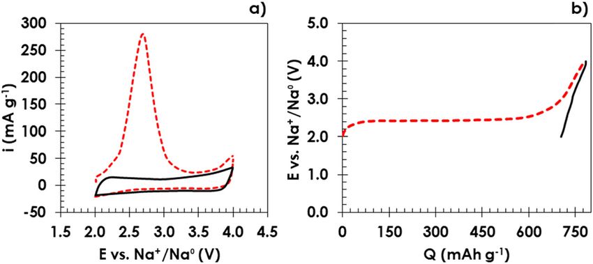
436 Pawel Jeżowski et al.
Figure 2: Electrochemical investigation and structural changes in NaBH4: (a) galvanostatic intermittent titration technique with 1 h current
pulse at current C/20 and 1 h OCV (during OCV period, the XRD spectra were taken); (b) structural changes in NaBH4 presented as XRD
spectra observed during the process of sodium extraction.
Figure 3: Galvanostatic oxidation of (a) NaBH4 (red dashed line) and gas pressure measurement (green continuous line) and (b) charge/
discharge profile of the positive electrode after the completion of NaBH4oxidation.
capacity of NaBH4) separated by 1 h OCV periods (Figure 2a) the profile of gas evolution (solid green line) and the
during which the XRD spectra were acquired (Figure 2b). galvanostatic polarization profile of the NaBH4/AC
It is presented that there is a visible disappearance of (dashed red line) during the electrochemical sodium
the signals corresponding to the cubic phase of NaBH4 extraction. The investigated electrode had an initial
(marked with Miller indices at about 29, 42, and 49°) pre- mass of 15 mg, and it contained 3.5 mg (9.3 × 10⁻⁵ mol)
sence when the amount of sodium atoms are electro- of NaBH4. The pressure change at 298 K related to BH−4
chemically removed from the structure of NaxBH4 (x → 0, oxidation was Δp = 112 kPa after 20 h of polarization.
where x corresponds to the amount of sodium atoms). The Hence, by application of the ideal gas law equation
only remaining signals after the complete extraction of (1), one can calculate the total number of moles of pro-
sodium ions are related to the cell construction and they duced gas:
correspond to the aluminium current collector (grey p×V 112 × 103 × 4.45 × 10−6
n= =
circle, near 39°) and a beryllium window (red squares, R×T 8.314 × 298 (1)
near 45° and 46°). = 2.01 × 10⁻⁴ mol
To measure a pressure change during the polariza-
tion of NaBH4/AC, an electrode cell with a pressure If the decomposition reaction follows equation (2)
sensor was used. According to the manufacturer, the [41]:
inner volume of this system is 4.45 cm3. Figure 3a shows NaBH4 → Na + B + ↑ 2H2 (2)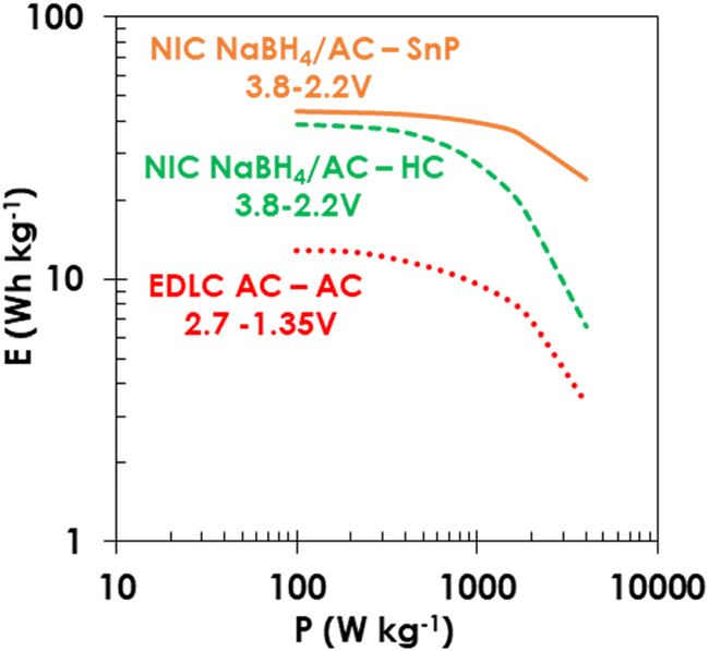
NaBH4 – a high-capacity material for next-generation sodium-ion capacitors 437
the amount of gas produced should be 1.85 × 10⁻⁴ mol formation of NIC. Potential limits were imposed as follows:
(starting from the initial 9.3 × 10⁻⁵ mol of NaBH4); and as 4 V for the positive electrode, 5 mV for HC electrode, or
it is presented in equation (1), the gas production is 2.01 × 100 mV for SnP vs Na+/Na0 to avoid any side reactions,
10−4 mol, which is the closest to the theoretical data. After such as electrolyte oxidation or sodium plating [19,42], or
the completion of electrochemical oxidation of NaBH4, in the case of SnP to achieve the optimal electrochemical
the positive electrode was again polarized (red dashed performance [36]. The pre-sodiation step was set at
curve), with no additional charge of the internal pressure C/20 rate, where C corresponds to the practical capacity
in the cell (Figure 3b). reached at the cut-off potential of HC (300 mA h g−1
Knowing the practical capacity of NaBH4 (700 mA h g−1), at 5 mV vs Na+/Na0) or tin phosphide (650 mA h g−1 at
HC (300 mA h g−1 at cut-off potential 5 mV vs Na+/Na0), 100 mV vs Na+/Na0). Figure 4a and c displays the poten-
and tin phosphide (650 mA h g−1 at cut-off potential 0.1 V tial profiles of electrodes and cell voltage during the for-
vs Na+/Na0), the composition of the positive electrode was mation of NIC. The sodium extraction from the NaBH4/
estimated according to the calculation reported elsewhere AC-positive electrode is characterized by one well-
[19]. In both cases of NICs, the mass ratio between the AC defined plateau at a potential near 2.4 V vs Na+/Na0
in the positive electrode and the active material in the (red dashed line). The potential profile of sodium inser-
negative electrode was equal to 1. In a cell with NaBH4/ tion (blue dotted line) in both cases drops drastically to
AC-positive electrode and HC or SnP as the negative elec- 1.0 V Na+/Na0 below which SEI formation occurs
trode, there was a sodium pin reference electrode, and it together with specific adsorption of sodium ions down
was possible to monitor the electrode potential during the to potential of ca. 0.1 V vs Na+/Na0 for HC [36,37,42] and
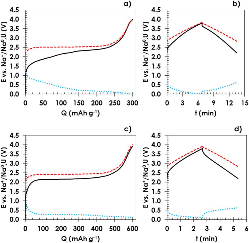
Figure 4: Pre-sodiation of a negative electrode (a) hard carbon, and (c) tin phosphide in an NIC with NaBH4/AC-positive electrode. Galvanostatic
profiles of the composite-positive electrode (red dashed line), -negative electrode (blue dotted line), and voltage of the cell (black solid line).
Galvanostatic charge/discharge profiles of NIC with (b) HC-negative electrode at 125 mA g−1 and with (d) SnP-negative electrode at 250 mA g−1
(values given per gram of the total mass of the electrodes) in the voltage range 2.2–3.8 V.438 Pawel Jeżowski et al. 0.2 V vs Na+/Na0 for SnP. Then the plateau formation is The dependence of specific capacitance (expressed seen which corresponds to the insertion of sodium ions per total mass of electrodes) versus the cycle number is for HC and the formation of alloy for SnP [36,37]. The shown in Figure 5a (NIC with HC-negative electrode) and voltage profile of the full cell (black solid line) is the Figure 5b (NIC with SnP-negative electrode). Both NICs potential difference between the positive and negative were cycled in the voltage range of 2.2–3.8 V; but for electrodes. After pre-sodiation and conditioning, the NIC with HC-negative electrode, the current density was NIC cells were cycled in the voltage range from 2.2 to 125 mA g−1; and for NIC with SnP-negative electrode, 3.8 V. The NIC cell with HC-negative electrode (Figure the current density was 250 mA g−1. During galvanostatic 4b) was cycled at the current density of 125 mA g−1 and cycling of NIC with HC-negative electrode at 125 mA g−1, NIC with SnP-negative electrode (Figure 4d) was cycled the NIC demonstrated a slow capacitance decrease during at the current density of 250 mA g−1 (values of current 5,000 cycles (Figure 5a) with a final 9% loss of capaci- density are presented per total mass of electrodes). The tance in comparison with the initial value. While the NIC potential of the positive composite electrode (red dashed cells with SnP-negative electrode cycled at 250 mA g−1 line) does not reach values lower than 2.0 V or higher displayed almost unchanged values of capacitance dur- than 4.1 V vs Na+/Na0, to avoid possible SEI formation ing the 5,000 cycles (Figure 5b) and the capacitance on the surface of AC or electrolyte oxidation, respectively value dropped only by 1%. [36,37,42]. The lowest value of potential was 3 mV vs Energy and power are characteristics of the assembled Na+/Na0 at the current density of 125 mA g−1. For the energy storage devices presented in Figure 6 as a Ragone NIC with SnP-negative electrode, the lowest reached plot. NICs were tested in the voltage from 2.2 to 3.8 V. A value of potential by the negative electrode was 111 mV symmetric EDLC with the electrodes made of the same at the current density of 250 mA g−1. AC as the one used in the NIC impregnated with the Figure 5: Specific capacitance of NIC with (a) hard carbon or (b) tin phosphide-negative electrode versus cycle number. Cells were galvanostatically charged/discharged in the voltage range of 2.2–3.8 V for 5,000 cycles at the current density (a) 125 mA g−1 or (b) 250 mA g−1.
NaBH4 – a high-capacity material for next-generation sodium-ion capacitors 439
4 Conclusion
Presented NICs used a sacrificial salt NaBH4, which has
not been so far reported in the literature as a source of
sodium ions for pre-sodiation of the negative electrodes
demonstrated to have a number of advantages. First,
the extraction of sodium ions from NaBH4 is completely
irreversible and at the lowest potential 2.4 V Na0/Na+
reported so far. Additionally, the high irreversible capa-
city of 700 mA h g−1 leads to the reduction in the sacri-
ficial material in the positive composite electrode to
25–35 wt%. Second, the cycling performance of the NIC
Figure 6: Ragone plots of the NICs prepared with NaBH4/AC compo- system is stable and the NICs can work for 5,000 cycles.
site-positive electrode and hard carbon (green dashed line) or tin Last, what is most important, the operational voltage of
phosphide (orange solid line) in the voltage range of 2.2–3.8 V. For
this system is high enough to achieve reasonable energy
comparison, the EDLC cell data are presented (red dotted line) using
the same AC as the electrode material, i.e. electrolyte as in NICs and and power output, reaching 33 W h kg−1 at 2 kW kg−1 in
charged up to 2.7 V. comparison with the conventional EDLCs.
same electrolyte was examined in the voltage range of Funding information: The authors are pleased to acknowl-
1.35–2.7 V [40]. Presented values are expressed per total edge the support of the Polish National Agency for
mass of the electrodes. Calculated values of the energy Academic Exchange in funding under the Bekker pro-
density for the NICs are around 40 W h kg−1 at power gramme, research stay and realization of NOVMAT pro-
values below 0.5 kW kg−1, which is almost four times ject (PPN/BEK/2018/1/00123/DEC/1). O.C. and T.B. would
higher than in the case of the EDLCs (red dotted line) like to acknowledge the French National Research Agency
with organic electrolytes, where the values of energy are (STORE-EX Labex Project ANR-10-LABX-76-01).
around 11 W h kg−1. Moreover, the NIC with SnP-negative
electrode (orange solid line) has superior electrochemical Author contributions: P. J. was involved in conceptuali-
performance in comparison with the NIC with HC elec- zation, data curation, methodology, resources, investiga-
trode (green dashed line). As it is presented in Figure 6, tion, visualization, writing of the original draft; P. J. and
NIC with SnP-negative electrode maintains the best reten- O. C. contributed to formal analysis and project adminis-
tion of energy value of about 33 W h kg−1 at power 2 kW kg−1, tration; and P. J., O. C., and T. B. were in charge of fund-
while the energy density for the NIC with HC-negative ing acquisition, validation, writing, review, and editing.
electrode was lower, i.e. ca. 18 W h kg−1; for comparison,
the energy density for EDLC cells at the same power was Conflict of interest: Pawel Jeżowski, who is the co-author
ca. 6 W h kg−1. of this article, is the current Editorial Board member of
In comparison with other NICs reported so far with an Open Chemistry. This fact did not affect the peer-review
HC-negative electrode, our cells achieved a longer cycle process. The authors declare no other conflicts of interest.
life than the one presented by Kuratani et al. [24]. Never-
theless, the potential of sodium insertion in HC is very Data availability statement: The data sets generated
low (near 5 mV vs Na0/Na+), which can contribute to during and/or analysed during the current study are avail-
sodium plating at higher current densities. Tin-based able from the corresponding author on reasonable request.
metallic anodes have a great advantage due to the high
capacity, even 850 mA h g−1; however, without a suitable
buffer matrix to adsorb the volume changes in the active
material during metal insertion/deinsertion, they show
very poor cycle life [43,44]. Sn4P3 alloy proves so far to References
be one of the better materials for the negative electrode
[1] Du Pasquier A, Plitz I, Menocal S, Amatucci G. A comparative
for a hybrid capacitor, and it demonstrates great improve-
study of Li-ion battery, supercapacitor and nonaqueous
ment as the achievable energy reaches 33 W h kg−1 at
asymmetric hybrid devices for automotive applications.
2 kW kg−1, i.e. excellent capacitance retention after 5,000 J Power Sources. 2003;115:171–8. doi: 10.1016/S0378-
cycles (99%). 7753(02)00718-8.440 Pawel Jeżowski et al.
[2] Naoi K, Ishimoto S, Isobe Y, Aoyagi S. High-rate nano- Li-ion capacitors. Electrochim Acta. 2016;206:440–5.
crystalline Li4Ti5O12 attached on carbon nano-fibers for hybrid doi: 10.1016/j.electacta.2015.12.034.
supercapacitors. J Power Sources. 2010;195:6250–4. [18] Jeżowski P, Fic K, Crosnier O, Brousse T, Béguin F. Lithium
doi: 10.1016/j.jpowsour.2009.12.104. rhenium(VII) oxide as a novel material for graphite pre-lithia-
[3] Béguin F, Frąckowiak E, editors. Supercapacitors: materials, tion in high performance lithium-ion capacitors. J Mater Chem
systems, and applications. Weinheim, Germany: A. 2016;4:12609–15. doi: 10.1039/C6TA03810G.
Wiley-VCH; 2013. [19] Jeżowski P, Crosnier O, Deunf E, Poizot P, Béguin F, Brousse T.
[4] Brousse T, Marchand R, Taberna P-L, Simon P. TiO2 (B)/acti- Safe and recyclable lithium-ion capacitors using sacrificial
vated carbon non-aqueous hybrid system for energy storage. organic lithium salt. Nat Mater. 2018;17:167–73. doi: 10.1038/
J Power Sources. 2006;158:571–7. doi: 10.1016/ nmat5029.
j.jpowsour.2005.09.020. [20] Park M-S, Lim Y-G, Park J-W, Kim J-S, Lee J-W, Kim JH, et al.
[5] Gorska B, Bujewska P, Fic K. Thiocyanates as attractive redox- Li2RuO3 as an additive for high-energy lithium-ion
active electrolytes for high-energy and environmentally- capacitors. J Phys Chem C. 2013;117:11471–8. doi: 10.1021/
friendly electrochemical capacitors. Phys Chem Chem Phys. jp4005828.
2017;19:7923–35. doi: 10.1039/C7CP00722A. [21] Park M-S, Lim Y-G, Hwang SM, Kim JH, Kim J-S, Dou SX, et al.
[6] Jeżowski P, Kowalczewski PŁ. Starch as a green binder for the Scalable integration of Li5FeO4 towards robust, high-perfor-
formulation of conducting glue in supercapacitors. Polymers. mance lithium-ion hybrid capacitors. ChemSusChem.
2019;11:1648. doi: 10.3390/polym11101648. 2014;7:3138–44. doi: 10.1002/cssc.201402397.
[7] Kerr JB. Advances in lithium-ion batteries edited by Walter A. [22] Lim Y-G, Kim D, Lim J-M, Kim J-S, Yu J-S, Kim Y-J, et al. Anti-
van Schalkwijk (University of Washington, Seattle) and Bruno fluorite Li6CoO4 as an alternative lithium source for lithium ion
Scrosati (University of Rome, “La Sapienza”). New York: capacitors: an experimental and first principles study. J Mater
Kluwer Academic/Plenum Publishers; 2002. x + 514 pp. Chem A. 2015;3:12377–85. doi: 10.1039/C5TA00297D.
$120.00. ISBN 0-306-47356-9; J Am Chem Soc. [23] Rumble J, editor. Handbook of chemistry and physics. Boca
2003;125:3670–1. doi: 10.1021/ja025282c. Raton, FL: CRC Press; 2020.
[8] Schroeder M, Winter M, Passerini S, Balducci A. On the cycling [24] Kuratani K, Yao M, Senoh H, Takeichi N, Sakai T, Kiyobayashi T.
stability of lithium-ion capacitors containing soft carbon as Na-ion capacitor using sodium pre-doped hard carbon and
anodic material. J Power Sources. 2013;238:388–94. activated carbon. Electrochim Acta. 2012;76:320–5.
doi: 10.1016/j.jpowsour.2013.04.045. doi: 10.1016/j.electacta.2012.05.040.
[9] Aida T, Murayama I, Yamada K, Morita M. Improvement in cycle [25] Ajuria J, Redondo E, Arnaiz M, Mysyk R, Rojo T, Goikolea E.
performance of a high-voltage hybrid electrochemical capa- Lithium and sodium ion capacitors with high energy and
citor. Electrochem Solid-State Lett. 2007;10:A93. doi: 10.1149/ power densities based on carbons from recycled olive pits.
1.2435511. J Power Sources. 2017;359:17–26. doi: 10.1016/
[10] Ding J, Hu W, Paek E, Mitlin D. Review of hybrid ion capacitors: j.jpowsour.2017.04.107.
from aqueous to lithium to sodium. Chem Rev. [26] Ding R, Qi L, Wang H. An investigation of spinel NiCo2O4 as
2018;118:6457–98. doi: 10.1021/acs.chemrev.8b00116. anode for Na-ion capacitors. Electrochim Acta.
[11] (a) Ando N, Kojima K, Tasaki S, Taguchi H, Fujii T, Hato Y, et al. 2013;114:726–35. doi: 10.1016/j.electacta.2013.10.113.
Organic electrolyte capacitor, US2007/0002524A1; 2007; [27] Chen Z, Augustyn V, Jia X, Xiao Q, Dunn B, Lu Y. High-perfor-
(b) Tanizaki H, Ando N, Hato Y. Lithium-ion capacit, mance sodium-ion pseudocapacitors based on hierarchically
EP1914764A1; 2007. porous nanowire composites. ACS Nano. 2012;6:4319–27.
[12] (a) Naoshi Y, Takashi C, Kazuyoshi O, Kuniyasu H. Lithium-ion doi: 10.1021/nn300920e.
capacitor, WO2012063545A1; 2012; (b) Makoto T, Chiaki M. [28] Kurra N, Alhabeb M, Maleski K, Wang C-H, Alshareef HN,
Lithium-ion capacit, JP2009059732A; 2009. Gogotsi Y. Bistacked titanium carbide (MXene) anodes for
[13] Aurbach D. A short review of failure mechanisms of lithium hybrid sodium-ion capacitors. ACS Energy Lett.
metal and lithiated graphite anodes in liquid electrolyte 2018;3:2094–100. doi: 10.1021/acsenergylett.8b01062.
solutions. Solid State Ion. 2002;148:405–16. doi: 10.1016/ [29] Kim MS, Lim E, Kim S, Jo C, Chun J, Lee J. General synthesis of
S0167-2738(02)00080-2. N-doped macroporous graphene-encapsulated mesoporous
[14] Luo W, Zhou L, Fu K, Yang Z, Wan J, Manno M, et al. A thermally metal oxides and their application as new anode materials for
conductive separator for stable Li metal anodes. Nano Lett. sodium-ion hybrid supercapacitors. Adv Funct Mater.
2015;15:6149–54. doi: 10.1021/acs.nanolett.5b02432. 2017;27:1603921. doi: 10.1002/adfm.201603921.
[15] Goodenough JB, Kim Y. Challenges for rechargeable Li [30] Dong J, Jiang Y, Li Q, Wei Q, Yang W, Tan S, et al.
batteries. Chem Mater. 2010;22:587–603. doi: 10.1021/ Pseudocapacitive titanium oxynitride mesoporous nanowires
cm901452z. with iso-oriented nanocrystals for ultrahigh-rate sodium ion
[16] Decaux C, Lota G, Raymundo-Piñero E, Frackowiak E, Béguin F. hybrid capacitors. J Mater Chem A. 2017;5:10827–35.
Electrochemical performance of a hybrid lithium-ion capacitor doi: 10.1039/C7TA00463J.
with a graphite anode preloaded from lithium bis(trifluoro- [31] Tong Z, Liu S, Zhou Y, Zhao J, Wu Y, Wang Y, et al. Rapid redox
methane)sulfonimide-based electrolyte. Electrochim Acta. kinetics in uniform sandwich-structured mesoporous Nb2O5/
2012;86:282–6. doi: 10.1016/j.electacta.2012.05.111. graphene/mesoporous Nb2O5 nanosheets for high-perfor-
[17] Jeżowski P, Fic K, Crosnier O, Brousse T, Béguin F. Use of mance sodium-ion supercapacitors. Energy Storage Mater.
sacrificial lithium nickel oxide for loading graphitic anode in 2018;13:223–32. doi: 10.1016/j.ensm.2017.12.005.NaBH4 – a high-capacity material for next-generation sodium-ion capacitors 441
[32] Zhu Y-E, Yang L, Sheng J, Chen Y, Gu H, Wei J, et al. Fast Sodium the negative electrode in sodium-ion capacitors.
storage in TiO2@CNT@C nanorods for high-performance 2021;375:137980. doi: 10.1016/j.electacta.2021.137980.
Na-ion capacitors. Adv Energy Mater. 2017;7:1701222. [39] Wang L, Zhang T, Yang S, Cheng F, Liang J, Chen J. A quantum-
doi: 10.1002/aenm.201701222. chemical study on the discharge reaction mechanism of
[33] Gu H, Kong L, Cui H, Zhou X, Xie Z, Zhou Z. Fabricating high- lithium-sulfur batteries. J Energy Chem. 2013;22:72–7.
performance sodium ion capacitors with P2- doi: 10.1016/S2095-4956(13)60009-1.
Na0.67Co0.5Mn0.5O2 and MOF-derived carbon. J Energy Chem. [40] Zhao J, Gao Y, Burke AF. Performance testing of super-
2019;28:79–84. doi: 10.1016/j.jechem.2018.01.012. capacitors: important issues and uncertainties. J Power
[34] Le Z, Liu F, Nie P, Li X, Liu X, Bian Z, et al. Pseudocapacitive Sources. 2017;363:327–40. doi: 10.1016/
sodium storage in mesoporous single-crystal-like TiO2 – j.jpowsour.2017.07.066.
graphene nanocomposite enables high-performance sodium- [41] Urgnani J, Torres FJ, Palumbo M, Baricco M. Hydrogen release
ion capacitors. ACS Nano. 2017;11:2952–60. doi: 10.1021/ from solid state NaBH4. Int J Hydrog Energy. 2008;33:3111–5.
acsnano.6b08332. doi: 10.1016/j.ijhydene.2008.03.031.
[35] Dong S, Shen L, Li H, Pang G, Dou H, Zhang X. Flexible sodium- [42] Cao WJ, Zheng JP. Li-ion capacitors with carbon cathode and
ion pseudocapacitors based on 3D Na2Ti3O7 nanosheet arrays/ hard carbon/stabilized lithium metal powder anode elec-
carbon textiles anodes. Adv Funct Mater. 2016;26:3703–10. trodes. J Power Sources. 2012;213:180–5. doi: 10.1016/
doi: 10.1002/adfm.201600264. j.jpowsour.2012.04.033.
[36] Chojnacka A, Pan X, Jeżowski P, Béguin F. High performance [43] Chojnacka A, Świętosławski M, Maziarz W, Dziembaj R,
hybrid sodium-ion capacitor with tin phosphide used as Molenda M. An influence of carbon matrix origin on electro-
battery-type negative electrode. Energy Storage Mater. chemical behaviour of carbon-tin anode nanocomposites.
2019;22:200–6. doi: 10.1016/j.ensm.2019.07.016. Electrochim Acta. 2016;209:7–16. doi: 10.1016/
[37] Pan X, Chojnacka A, Jeżowski P, Béguin F. Na2S sacrificial j.electacta.2016.05.044.
cathodic material for high performance sodium-ion capacitors. [44] Chojnacka A, Molenda M, Bakierska M, Dziembaj R.
Electrochim Acta. 2019;318:471–8. doi: 10.1016/ Electrochemical performance of Sn/SnO2 nanoparticles
j.electacta.2019.06.086. encapsulated in carbon matrix derived from plant polysac-
[38] Jeżowski P, Chojnacka A, Pan X, Béguin F. Sodium amide as a charides. ECS Trans. 2015;64:165–71. doi: 10.1149/
“zero dead mass” sacrificial material for the pre-sodiation of 06422.0165ecst.You can also read