Encrypting A 7.88ghz Frequency Message Within A Chaotic Carrier by Optical Feedback
←
→
Page content transcription
If your browser does not render page correctly, please read the page content below
Iraqi Academics Syndicate International Conference for Pure and Applied Sciences          IOP Publishing
Journal of Physics: Conference Series            1818 (2021) 012027 doi:10.1088/1742-6596/1818/1/012027

     Encrypting A 7.88ghz Frequency Message Within A
     Chaotic Carrier by Optical Feedback

                          Ayser A. Hemed*1, Thorsten Ackemann2, Hani J. Kbashi3 and Baha T.
                          Chead4
                          1
                            Department of Physics, college of education, Mustansiriyah University,
                          Baghdad, IQ
                          2
                            Photonics at University of Strathclyde, Glasgow, UK
                          3
                            School of Engineering and Applied Science, AIPT, Aston University, Aston,
                          UK.
                          4
                            Department of Physics, college of Science, University of Baghdad, Baghdad, IQ

                          Emails:
                          1. ayser.hemed@uomustansiriyah.edu.iq
                          2. thorsten.ackemann@strath.ac.uk
                          3. kbashihj@aston.ac.uk
                          4. bahatoama@yahoo.com

                          Abstract: A new laser system is suggested and experimentally verified as a chaotic
                          transmitter for a secure optical communication system. The laser source kind is a
                          distributed feedback with a peak wavelength 1310nm and maximum power 5mW. A doubly
                          external cavity with 85cm of length is constructed via air.
                          Chaotic signal is achieved successfully after the laser reach of coherence collapse, with a
                          very wide band spectrum (12GHz). This value is capable to increase subjecting to several
                          parameters based on optical feedback (OFB) such as laser current operating level, beam
                          focusing, polarization control, etc. In order to test a message hiding possibility, a frequency
                          message is modulated directly into the laser, which is connected with the laser source using
                          a bias tee. For the free running (solitary) semiconductor laser, the maximum available direct
                          current modulation is: 3GHz/mA, while this value can be increased by this technique. This
                          gives the possibility for very high modulation values and increasing data package volume
                          that can send securely in the applications that requires immunity.

     1. Modulation with Semiconductor Laser:
     Direct modulation into semiconductor laser (SL) represents one technique for chaos generation
     (CG). Increasing transmission capacity (modulation within chaos carriers itself) represents a goal
     *
         Corresponding Author

              Content from this work may be used under the terms of the Creative Commons Attribution 3.0 licence. Any further distribution
              of this work must maintain attribution to the author(s) and the title of the work, journal citation and DOI.
Published under licence by IOP Publishing Ltd                          1
Iraqi Academics Syndicate International Conference for Pure and Applied Sciences IOP Publishing
Journal of Physics: Conference Series 1818 (2021) 012027 doi:10.1088/1742-6596/1818/1/012027
for wide band secure optical communications. Adding an external modulation to the pumping
current (pump modulation) for a laser system as shown in figure 1, laser intensity chaotic instability
may appear. External frequency modulation frequency needs to be normalized around laser
relaxation oscillation frequency (ROF), so that nonlinear interaction between that frequency
external modulation and later frequency may result in CG.
The frequency EM can also be added to the loss of the internal laser cavity, which is named as loss
modulation. From the other hand, chaotic dynamics is typically observed through the quasi
periodicity route to chaos linearly related to strength of frequency external modulation [1].
Figure 1. Chaos generation by external modulation technique.
For applications involving millimeter wave systems; Radhakrishnan Nagarajan et. al.
experimented a Fabry-Perot laser type and demonstrated a system implementation with external
cavity laser capable of transmitting and receiving narrow-band digital data modulated on a
millimeter wave subcarrier at 35 GHz. That system, adapts sharpening pulses, i.e. in the absence
of chaotic broad bands. This author also experimented a DFB Laser, the same as what we used,
with FBG instead of external mirror and he indicated increasing noise, which is agree with what
we achieved after the coherence collapse reached [2].
2. Semiconductor Laser with Optical Feedback
OFB, alternative name to it is self-mixing interference, means change in both laser intensity and
polarization states with a small fraction of the output laser re-injected the laser cavity. Inserting
anisotropy to this part, as a feedback, by components such as, polarizer, liquid crystals or wave
plates, when they are placed into the feedback cavity bath, it is found that the laser become self-
mixing interference. This is under modulation for that parameter in laser beam outside its cavity
[3]. SL with OFB display large chaotic dynamic behavior, which are mapped as periodic
oscillations, period doubling, quasi-period, and routes to chaos (coherence collapse). Phase
variation, polarization, time delay for re-injected field back to laser cavity all associated with
previous effects. For strong OFB, the induced oscillations frequency may be corresponding to laser
external cavity resonance frequency.
Ref. [5] suggested a model employing uses lateral OFB of slow light to enhance the modulation
bandwidth of a SL of type ‘vertical cavity surface emitting laser (VCSELs)’ with increasing
modulation bandwidth up to 40 GHz. It is still not complete understood how fast we can directly
modulate SL radio over fiber applications [4]. Transmitting coherent light wave with high bit rate
into mono-mode optical communication systems needs more stable lasers with narrower
linewidths. EC SLs is a one more effective practical technique for meeting this goal [5].
From the other hand, VCSLs SL with optical injection can also give another interesting chaotic
dynamic, one of them is the so called optical rogue (RW) waves. Recently experimentally satisfied
by ref. [6]. It was found that optical RW associated with optical injection appeared as a result of
collision in chaotic pulses that developed due to the electrical pump injection [6].
2Iraqi Academics Syndicate International Conference for Pure and Applied Sciences IOP Publishing
Journal of Physics: Conference Series 1818 (2021) 012027 doi:10.1088/1742-6596/1818/1/012027
Dynamics mentioned above, is governed by nonlinear light-matter interaction treatment in the
active medium of the laser, quantum noise due to spontaneous emission and time-delayed feedback
are both included. The ROF are capable to increase with the laser pump current. Due to the
characteristic life time of both carriers and photons (10−9s and 10−12s, respectively) these ROF can
take order of a few GHz.
Key effect for meeting OFB is the laser threshold, named threshold reduction, TR or
(. ) which is calculated according to the following equation . = × 100 where is
the solitary laser threshold, is the laser threshold with optical feedback [7]. TR is the first
considered and most important indication to approve the light-active medium interaction [8]. It was
achieved that TR value depends on the technique at which the reflected light follows. These values
of TR were ranged from 4.2% to 19.77%. Additional parameters also affected that parameter such
as; external cavity length i.e. time delay for one round trip, type of that external cavity (stable or
unstable cavity), back reflected beam ratio, laser type and its beam divergence, finally alignment
at which all beams set, all these of course with a constant operating temperature [9]. Larger value
OFB TR means that a strong feedback is reached, this can dramatically reduce the phase noises
(frequency chirp) [5].
For each TR value there exists associated nonlinearities appears within laser emission at that
value of feedback. Thus, for each pump current one can find different emission characteristics,
when beam parameter changed as well, the dynamics become more complicated. Beam
polarization, power attenuation, nonlinearity inserted externally into the delayed beam,
amplification all can be changed to enrich these dynamics [10] and even inserting acoust-optic
modulators to achieve frequency-shifted OFB measurements using a solid-state microchip laser
(for sensing applications) [11]. The delay time can be measured by the equation: = 2 /,
wher and is the external cavity length and refractive index. The model of external cavity
is shown in figure 2, where is the internal cavity back mirror reflectivity, is the internal
cavity front mirror reflectivity, and external cavity mirror reflectivity [12].
Figure 2. Depicts schematically a SL with external OFBB [12]
Due to the ROFs of the SL, the laser EC can be classified as a short external cavity, if the light
delay time is of the order (or smaller than) the relaxation time (OFB takes order of hundreds of
picoseconds); and long external cavity, if the light delay time is much longer than that time.
Coherence Collapse (CC) effect refers to a large increase in the laser pulse linewidth of the laser
mode (from hundreds of MHz to tens of GHz). This regime reached with moderate to high feedback
strengths, and pump currents far above the solitary laser threshold [13].
3Iraqi Academics Syndicate International Conference for Pure and Applied Sciences IOP Publishing
Journal of Physics: Conference Series 1818 (2021) 012027 doi:10.1088/1742-6596/1818/1/012027
3. Rate Equations with Modulation:
When specific parameters of the laser external cavity are modified, its output steady-state
system became unstable to small fluctuations, current modulation intensity. This is due to either
polarization or pump power that leads to the development of a periodic frequency modulation.
Modulation intensity can be either spontaneous or stimulated. The pump power for such effect to
be occur is only slightly above the solitary laser threshold. This continues wave (CW) emission
was found to be more unstable, where its emission can undergo from spontaneous temporal
modulation into a periodic pulse train. This translation from periodic modulation dynamics are
typically described in the spatiotemporal domain [6].
Since the pioneer study carried out by R. Lang et.al., many studies dealt with SL under OFB. R.
Lang suggested theoretical model and approved it experimentally for the laser stability with weak
optical feedback which is based on traditional analysis. The model is hybrid (mixed) cross between
two models; i.e both node and traveling wave approach. They have been experimentally approved
that a laser with external OFB can be multi-stable and show hysteresis-like phenomena, identical
to those of nonlinear Fabry-Perot resonator. It has also been indicated that the dynamic properties
of these lasers are strongly affected by laser external cavity feedback, this is depending on
interference conditions between reflected light and the field constructed inside the laser diode
internal resonator. An external feedback term is added under the steady-state conditions, in to a
solitary SL equation in complex form, thus the field equation for a complex cavity laser setup is
such that [7];
1
()
= !"#$ () + (%() − Γ' )* ()
+ ,( − )
-( 3)
2
where; #$ ()is the resonant frequency for diode cavity longitudinal mode, it is defined with an
integer N as #$ () = 45/67 , Γ' is the cavity loss of the diode, and c is the light velocity in
vacuum, last term on the right-hand side represents the external feedback, , is a coefficient related
with cavity parameters, and it is given as; , = 8/267 , external cavity mirrors reflectivities are
r1 and r3; 8 = (1 − )( / )9/ is a coupling strength measure between the two cavities. For
above expression that associated with external feedback, multiple reflections in laser external cavity
have been neglected [7].
This classical approach meets acceptance with only weak feedback from a single mirror, and has
been shown to be a limit of more accurate models.
For the problem of emission with strong OFB, dynamics of SL under IM and OFB are described
by time-delay rate equations of the carrier number, photon number and optical phase. According to
this model given by ref. [14], gain of threshold is determined by lifetime of photon inside internal
laser cavity of length LD, and refractive index nD, and OFB function that describing the time delay
of laser light doing the round trips (i.e., multiple reflections) within the external cavity (of length
Lex and refractive index nex). This cavity formed from distance between laser facet (of reflectivity
Reff and EC mirror R3) figure 2. Coupling coefficient Kex defines the strength of OFB which is
determined by the ratio between Reff and R3. Under single type modulation, the injection current
I(t) is constructed from a bias component Ib, and a sinusoidal component of wave amplitude Im and
modulation frequency :; [14][15];
() = < + ; sin (25:; )
Proper analysis includes the coupling of laser diode to an external optical system, must treat open
cavities type, i.e. cavities that has low quality factor. Even for a single laser diode cavity, the
4Iraqi Academics Syndicate International Conference for Pure and Applied Sciences IOP Publishing
Journal of Physics: Conference Series 1818 (2021) 012027 doi:10.1088/1742-6596/1818/1/012027
primary approach of defining basic modes with equivalent mirror losses uniformly distributed
along the cavity, underestimates the coupling between spontaneous-emission noise inside the laser
mode [16].
Thus, complete picture for modeling laser dynamics under OFB must including an operator that
completely describes feedback effects, then applied this technique to various suggested feedback
geometries [12], variation in the diode internal cavity optical path length LD, which is caused by
active medium crystal refractive index variation due to the active region instantaneous temperature
change with current variation [7].
Hjleme in his series researches, presented a theoretical model extended the analysis to include all
ROs, and frequency and intensity noise spectra with developing it in term of convenient operators
that easily transform in the linearized noise spectra. The theory is valid for arbitrary (dynamical)
strong feedback [15].
4. Experimental Set up:
Throughout this study, air as a linear medium( ≈ 1), is referred to as a free space. Chaos
generation via self OFBB is divided into two types: fiber loop-mirror delayed OFBB and air EC
delayed feedback. According to latter technique different geometrical configurations are available.
The selection was located in to the one that given in figure 3.
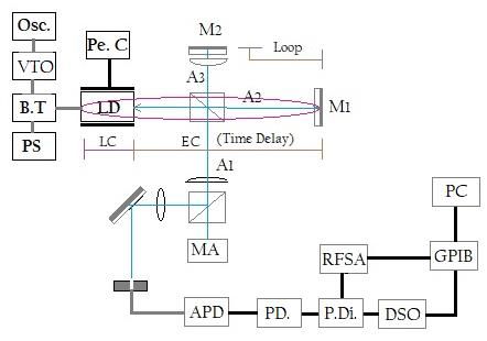
Figure 3. Experimental set up configuration for modulation in to chaos.
Abbreviations are as mentioned in text.
As shown in figure 3; LD: is ?725B11C ThorLabs co. laser source, Pe. C.; is Peltier
cell/temperature stabilized - better than 0.02oC, DSO: is TDS6124C Tektronix co., digital storage
oscilloscope, 12 GHz bandwidth, RFSA; is MS2665C Anritsu co., 21.2GHz, RF spectrum analyser,
B.T.; is ZFBT-6GW+, Minicircuits co bias-tee to mixing pump current and frequency, P.Di.; is (6
dB) Picoseconds Pulse lab. Co. power divider, modulators, which are: 2019A Marconi, 1.024GHz
SG, X2 FK-3000+, frequency multiplier, VTO: 8000 HP Varactor-Tuned Oscillators, “600 MHz
to 10.5 GHz" and PC is the lab. computer for deriving Labveiw program. Light submitted by LD
pass through 50:50 non-polarized beam splitter, NPBS, one part, A1, from this light reflected toward
the output direction, while the transmitted part, A2 is going to hit a high reflectivity (99.5%)
dielectric external mirror M1. The later part back reflected from the right side OFB NPBS itself.
5Iraqi Academics Syndicate International Conference for Pure and Applied Sciences IOP Publishing
Journal of Physics: Conference Series 1818 (2021) 012027 doi:10.1088/1742-6596/1818/1/012027
Again, part OFB it will transmit directly to inside the LD and the reflected part, A3, will go to a
second (perpendicular to M1) dielectric mirror M2 (with reflectivity OFB 99.5%), then back to the
same NPBS. Part from it will transmit (interfering with A1) to the output direction and the reflected
part will also enter the LD. Accordingly, the EC length will be summation of 85cm plus 20cm, i.e.
double EC geometry is constructed. Overlap will give a various types of modes to inside the laser
internal cavity. This will disturb solitary lasing RO modes modifying the overall output via the
coherence collapse under the effect of strong feedback. The back reflected power is controlled by
a variable filter, and the matching between the forward and backward beams is monitored by a D.C.
monitoring for the laser signal and with controlled beams by the 3-D mirror mounting.
External time delay for part of back reflected beam is 5nS (single long path), and another part
delay will be 1nS (single short path), and a third part will be a summation for both of these two
delays, 6nS. As a result, under the strong feedback perturbation, the laser will run with very broad
band chaotic carrier. Selection for this geometry will make the signal more complicated and be
more stable and gives rise to security degree. TR ratio for this experiment was 10.85% at constant
operating temperature 14.8∓0.02 oC. Temperature for heat-sink is applied and controlled more
precisely to avoid both drift and longitudinal mode jumping. Noting that MA in output arm of figure
3 is refer to our more analysis direction not included in this article.
Light is passing through the NPBS two times, i.e. beam is suffered from attenuation two times, in
additional to the remaining loss from mirrors with reflectivity of > 99.5%. A NPBS was inserted
between the laser focusing lens and the EC mirror M1, as shown in figure 3, and the largest power
of the beam after passing the NPBS is the A2, in order to increase the feedback strength. Attenuation
plate (with different values) are placed between the feedback mirror and the beam splitter while the
other option was to decrease or increase feedback strength by EC mirror micro tuning in x or y
direction, which was not preferred.
Main feature of the large cavity regimes is that laser dynamics are not sensitive against
variations of the phase with which reflected light re-enters inside the laser cavity. Noting that, even
though it appears that the frequency stability is better for longer distance cavities, the number of
possible cavity modes also increase, making the laser subject to mode jump. The sensitivity of the
operating frequency to external cavity resonance variations or equivalently variations of cavity is
given by [1];
H#' −2
≅ K#
H J
where K# = 25/L is the free spectral rang for cavity. In other words, a change of length of J/2
will tune the laser emission frequency an amount equal to the free spectral range. Cavity length
perturbations could easily be due to air temperature, pressure variations that could set the limit on
the stability of a real system [12]. While a mode hopping between external cavity modes in analogy
with noise driven transitions of a potential between potential valleys.
The aim of present work is to achieve maximum broadening chaos signal in order to modulating
it with highest FM message. This goal was achieved in practice with an 85cm length, according to
our configuration set up.
The laser with a relatively short EC and weak feedback strength works in a stationary regime
independent on how much is the pumping. However, for a longer EC the laser dynamics is very
rich. Thus, in order to generate the chaos, as a carrier signal, in which effect, CC should be
achieved; the latter is not possible for short length cavities. The region of which is continuous un-
stable, and independent of phase, which requires larger lengths ECs [16]. Thus laser should be
running with high instabilities dynamics and out of his steady CW state.
6Iraqi Academics Syndicate International Conference for Pure and Applied Sciences IOP Publishing
Journal of Physics: Conference Series 1818 (2021) 012027 doi:10.1088/1742-6596/1818/1/012027
From view point of interference theory, as mentioned above, laser light inside cavity is a
standing wave between two cavity mirrors. This standing wave consists of two light waves with
equal amplitudes and frequencies but with opposite propagation directions, this theory is true for
both internal and also external laser cavities. Non-linear interaction between the EC modes
(separated by a frequency M = 6/τ) and the RO frequency, MN of the solitary free running laser
are dominant in systems that subjects to OFB [17, 18].
EC generates series resonant frequencies to the laser emitted spectrum. Competition and
interplay between them and internal laser cavity frequencies becomes a function to the feedback
level. Increasing this parameter causes successive new instabilities which give rise to chaotic
behavior, especially in case of running the laser far away from its free running threshold. Several
different chaotic transitions might be occurring, but, the quasi-periodic-route is the most common
one.
By changing the strength of feedback or its delay time, laser can be operated in a chaotic pulsing
state. However, the rate of laser pulsation is limited by its RO frequencies, which cannot be
increased by adjusting the feedback parameters, while, this is possible in OFB regime [19].
According to that, RO and the EC frequencies appears sequentially and are incommensurate.
Generally, in time delayed systems, for small delay, low dimensional attractors arise, and on the
opposite, in the long delay limit, more complex high dimensional dynamics appears. Since time
delayed dynamical systems appear in many physical configurations, a lot of potential has been done
to understand how the dynamics and the complexity OFB the attractors vary with the delay time
[8]
In general, dynamics of laser output originate from destabilized laser that has RO of the solitary
SL and the interaction of the system modes with the laser external cavity modes (fEC=1/τ) for
different feedback parameters. RO is given by;
9/
1 %$ P
MN = O R
25 Q
9/
Where Es is the free running electric field amplitude and is given by; P = S(T − 4 U /P )Q V
where 4 U is the threshold carrier density.
For the laser system subjecting to OFB, period doubling rout occurs when the RO and the EC
modes or their harmonics are locked with each other’s. As the feedback strength is increased, the
new created frequencies follow this sequence; M9 , M9 /2, M9 /4, M9 /8 … till getting chaos. Route in
principle occurs when delay ratio, MN /MZ[ (or MN ), is small. While quasi periodic route of ten
occurs for high delay portion, starting to bifurcate in phase space from stationary solution to stable
limit cycle followed by torus as the feedback increases. The first start frequency M9 is very close to
MN , while the second oscillation frequency Morginates from the fundamental EC frequency MZ[ .
The next two frequencies M9and M will aligned in order to lock at ratio of M9⁄M = 4/3 due to the
nonlinear coupling.
As the feedback ratio increases, a third oscillation frequency is arising, which is important for
chaos, it construct from the second cavity mode. Chaos occurs most frequently via quasi-periodic
route, as the frequency locking condition is not usually satisfied. Even when satisfied, a small
change in either laser external cavity length (~ J⁄4) or the injection current (~0.1%) can break
down the locking and different route produced [20].
7Iraqi Academics Syndicate International Conference for Pure and Applied Sciences IOP Publishing
Journal of Physics: Conference Series 1818 (2021) 012027 doi:10.1088/1742-6596/1818/1/012027
5. Results and discussion:
5.1. Free Running Laser:
Continuing to our experiments for laser operation with OFB, results with 20cm EC (via linear air)
which is given in Ref. [10] and that via optical fiber Ref. [21]. Practical laser operation
characteristics in free running case is examined at first to ensure its real operation without OFB.
For this measurements, A2 & A3 beam directions to exclude from any feedback by blocking them.
The first NPBS is located at 5.7cm in front of the laser output. The measured splitting ratio in
practice for the real laser wavelength was: 50.50%: 43.84% for I9 : I, respectively. That’s means
a 9.4% portion is considered as a loss.
Temperature was chosen to be: 14.8 oC, in order to avoid any water drops which probably
condensed on laser body due to temperature difference inside the laboratory. The measured FR
laser threshold current was 4.03mA, figure (4) and its maximum FR output measured optical power
is 6.73mW at 30mA. This is after including the reduction of power due to both NPBS and
absorption scattering due to dust losses. In case of FB, the measured TR ratio is 10.58% with
maximum optical power increase ratio 0.153%.
(B)
Output Optical Power (mW)
Pmax. = 7.76mW
8
Pmax. = 6.73mW
6 T = 14.7oC, direct foucsed beam.
TR = 10.58%
4 Power increasing = 15.3%
2
Free Running
EC = 85cm
0
0 5 10 15 20 25 30
Bias Current (mA)
Figure 4. Experimental measurments for light – current two curves
with and without and OFB
Observation with free running laser in majority pump current levels shows that LD spectrum
has an emission spectrum contains more than single longitudinal mode with low mode suppression
ratio, and wide line shape. As a result, the single lasing mode was found dominant in two bias
current levels, near FR threshold and far away from it. In intermediate, the laser makes interplay
between the two dominant neighbour frequencies.
5.2. Laser with optical feedback:
Running the laser under OFB, in 85cm doubly EC, stimulating laser response extraordinarily. It is
easy to notice a wide broadening in its pulse line shape function, fig. (5), Linear fitting relation
resulted between pump current and that function. where the laser with OFB by defaults translated
from CW into pulsation mode. Laser was operated at multiple longitudinal lasing modes in majority
of its injection current levels, with a large reduction (78%) in its optical signal amplitude in case of
OFB than that in FR case.
8Iraqi Academics Syndicate International Conference for Pure and Applied Sciences IOP Publishing
Journal of Physics: Conference Series 1818 (2021) 012027 doi:10.1088/1742-6596/1818/1/012027
OFB with doubly mirror, 85cm
1.0 Linear Fit of FWHM
0.9
FWHM (GHz)
0.8
0.7
0.6
0.5
5 10 15 20 25 30
injection current (mA)
Figure 5. Experimental results between laser pump current and FWHM.
For the selected pump current level, in which purely single mode lasing laser operation in a free
running, we select this level to exam the spectrum under optical feedback. Results given in figure
6, shows that the spectrum be boarder and multi spikes growth under the influence of strong
feedback. Spectrum occupy a twelve GHz in wide, and follow a Gaussian fitting. Measurement is
done with RF spectrum analyser furthermore the DSO and both spectra are identical. Those
frequencies gave the picture of interfering between solitary laser frequency with EC frequency
which was very sensitive to the laser pump level.
Frequency
0 2 4 6 8 10 12 14 16 18 20
0
0.08 5.4 mA OFB
-2000
Phase
0.06 -4000
0.04
0.012
stronger OFB
Power (dBm)
0.02 0.010
with 85cm doubly EC
0.00 0.008 i = 5.4mA
Amplitude
-0.02 0.006
-0.04 0.004
-0.06 0.002
-0.08 0.000
-10 0 10 20
0 2 4 6 8 10 12 14 16 18 20
Frequency (GHz)
Frequency (GHz)
5.4mA, strong OFB
Gauss Fit of Book1_B
10
FWHM=2.49GHz
5
0
Power (dBm)
-5
-10
-15
-20
-25
0 2 4 6 8 10 12 14
Frequency (GHz)
Figure 6. Dynamics associated with stronger OFB in 85cm doubly EC without modulation.
5.3. Masked Modulation:
High-frequency modulation of laser beams is important requirement for various fields including
atomic physics, metrology, and optical communications [16][ 22]. The high-frequency modulation
of LDs has been a subject of active research for signal transmission in digital and analogue fiber-
optic communications, fiber-optic links, delay lines, and phased array beam steering. High-
frequency modulation of InGaAsP has achieved bandwidths of 23 GHz in periodic laser emission
[23]. Thus, it was interesting for our study to increase modulation bandwidth in chaotic laser
emission instead.
Modulation in present set up, given in figure 3, was made by modulation into the DC current
injected into the LD, i.e. as an AC signal. According to measured RF spectra, observations indicated
9Iraqi Academics Syndicate International Conference for Pure and Applied Sciences IOP Publishing
Journal of Physics: Conference Series 1818 (2021) 012027 doi:10.1088/1742-6596/1818/1/012027
in the last section. The obtained chaos signals were wideband. It was even in low laser deriving
currents, at least 8 GHz OFB bandwidth; otherwise, it reaches (12+) GHz in high value deriving
currents. This is roughly the same observation for TR = 4.9% and 10.58%.
Experiments in modulation started by using the signal generator alone i.e. :; = 1.040GHz, then
a wide band (140 to 3000 MHz) frequency multiplier (FK-3000, constant output, doubler harmonic
conversation) is inserted between signal generator and bias-tee for doubling the frequency value
before modulating it. Maximum modulation, in this stage, was up to 2.08GHz. In order to increase
modulation limit, an oscillator (VTO–8240, 2400–3700MHz then, VTO–8650, 6500-8600 MHz,
were used. Both were Varactor-Tuned Oscillator frequency multiplier. As it is shown in figure 7,
the FM message was implemented completely within the chaos carrier signal. This was available
for four different laser input current levels.
0.015
(A) Frequency
5.0mA, 2.08GHz, -1dBm 0 2 4 6 8 10 12 14 16 18 20
4000
Phase
0.010 2000
0
Power (dBm)
0.005
m = 2.08GHZ
0.000
0.0010 i = 5.0mA
RF level = -1dBm
Amplitude
-0.005
-0.010 0.0005
-0.015
0.0000
-20 -15 -10 -5 0 5 10 15 20
0 2 4 6 8 10 12 14 16 18 20
Time (nS) Frequency (GHz)
-6
5.5mA, 2.08GHz, -1dBm
-8
-10
-12
Power (dBm)
-14
-16
-18
-20
-22
-24
1 2 3 4 5 6 7 8
Frequency (GHz)
Figure 7. Laser spectra with :; = 2.08%bc within chaos signal generated by doubly EC, 85cm
in length.
As shown in figure 8, there were three spectra for higher RF levels (:; =3.76GHz) harmonics are
easy to distinguish in periodic laser oscillation when modulating a solitary laser experimentally.
40 4.26mA, 3.76GHz
30 (3.76, 25.71) 8.27mA, 3.76GHz
Power (dBm)
20 28.7mA, 3.76GHz
(7.52, 9.25)
10
0
-10
-20
0 2 4 6 8 10 12 14 16 18 20
Frequency (GHz)
Figure 8. Laser periodic RF spectra with νe = 3.76GHz for three modulation Rf levels.
In figure 9 row-A, FR laser emission has a sharp optical spectrum; with a characteristic
peak at 7.880GHz, which is exactly the modulated signal. Modulation with the same value but laser
10Iraqi Academics Syndicate International Conference for Pure and Applied Sciences IOP Publishing
Journal of Physics: Conference Series 1818 (2021) 012027 doi:10.1088/1742-6596/1818/1/012027
is under the effect of OFBB is given in the same figure 10 row –B. Laser input currents, was near
FR threshold, in which, the message was successfully fully hidden within chaotic carriers that has
an extended to more than 10GHz signal.
Frequency
0 2 4 6 8 10 12 14 16 18 20 22 24
0.015 4.49mA (A) 16000
14000
Phase
12000
0.010 10000
8000
0.005
Free Running Laser
Amplitude
0.0015
0.000
m = 7.880GHz
Laser input current = 4.49mA
Amplitude
0.0010
-0.005
-0.010 0.0005
-0.015
0.0000
-20 -10 0 10 20 0 2 4 6 8 10 12 14 16 18 20 22 24
Time (nS) Frequency (GHz)
FR (Periodic) laser, 4.49mA
-8
-10
-12
2.66GHz 7.880GHz
Power (dBm)
-14
-16
-18
-20
-22
-24
-26
0 1 2 3 4 5 6 7 8 9 10
Frequency (GHz)
Follows in the next page
Frequency
0.06 4.49mA (B) 8000
0 2 4 6 8 10 12 14 16 18 20 22
6000
Phase
4000
0.04
2000
Amplitude
0.005
0.02 Laser Input current = 4.49mA
0.004
m = 7.880GHz
Amplitude
0.00 0.003
0.002
-0.02
0.001
-0.04
0.000
-20 -10 0 10 20
0 2 4 6 8 10 12 14 16 18 20 22
Time (nS) Frequency
4.49mA
6 Gauss Fit of Book1_B
3 FWHM=4.57 GHz
0
Power (dBm)
-3
-6
-9
-12
-15
-18
-21
0 1 2 3 4 5 6 7 8 9 10 11
Frequency (GHz)
Figure 9. Laser spectra associated with modulation value νm =7.880GHz and RF level (+9dBm).
(A) Modulation with a FR laser, and (B) Modulation with a chaotic oscillation.
This result disagreed with what indicated by Rongqing Hui [5]. He mentioned that long EC with
OFB is preferred in the strong-feedback regime, in which laser operates stably with ‘narrower’
linewidths for all phases of the feedback. While, L. Hollberg et.al [24] showed that the maximum
available νe for SL by direct current modulation is: 3GHz/mA, but with free running. Worth to
mention is that laser ability for direct bias current modulation can be calculated by the so called,
jk
FM index, (h = ) which means decrease of h with increasing laser operation bias current.
lp
11Iraqi Academics Syndicate International Conference for Pure and Applied Sciences IOP Publishing
Journal of Physics: Conference Series 1818 (2021) 012027 doi:10.1088/1742-6596/1818/1/012027
Enhancement of DFB SL available by the technique of EC. In such a technique, internal laser cavity
eliminated and νe is matched to the free spectral range of OFB in the EC.
6. Conclusions:
The direct modulation of SLs can be enhanced as well as employed for hiding a transmitted
message. This is inside the resonant frequencies that generated intentionally by a long EC.
Complexity for this cavity geometry could generate increased complicate spectrum for the
transmitter. This spectrum can also be broader by doing external modulation to the external part of
that laser cavity, by change any part of its beam parameters.
7. References
[1] Uchida Atsushi 2012 Optical communication with chaotic lasers: applications of nonlinear
dynamics and synchronization (Wiley-VCH Verlag & Co. KGaA, Boschstr. 12, 69469 Weinheim,
Germany, Printed in Singapore) chapter 2 pp 44.
[2] Nagarajan Radhakrishnan, Levy Shmuel and Bowers John E 1994 Millimeter wave narrow
bald optical fiber links using external cavity semiconductor lasers J. Lig. Wave Tech. 12, no. 1pp
127-137.
[3] Chen Wenxue and Hu Xinhan 2016 Intensity modulation in laser with asymmetric optical
feedback Elsevier GmbH J. of Optik 127, Issue 4, , pp 2083-2085.
[4] Ahmed Moustafa, Bakry Ahmed, Altuwirqi Reem, Alghamdi Mohamed S and Koyama
Fumio 2013 Enhancing modulation bandwidth of semiconductor lasers beyond 50 GHz by strong
optical for use in millimeter-wave radio over fiber links Japanese J. Applied Physics, 52 No. 12R
124103 pp 1-5.
[5] Hui Rongqing and Wu Yizun 1989 Noise and frequency chirping in external-cavity
semiconductor lasers J. Optics Letters, 14, No. 13, pp 668-670.
[6] Kbashi Hani Jassim 2018 Vector optical rogue waves in mode-Llocked fibre lasers A Ph.D.
dissertation, Engineering and Applied Science, Aston Institute of Photonics Technology, Aston
University.
[7] Lang Roy and Kohroh Kobayash 1980 External optical feedback effects on semiconductor
injection laser properties IEEE J. Quant. Electr., QE-16, no. 3, pp 347-355.
[8] Hemed Ayser A 2011 Chaos generation methods in optical communication systems A Ph.D.
dissertation department of Physics college of Science, University of Baghdad, Iraq.
[9] Hemed Ayser A, Chead Baha T, Kbashi Hani J 2015 Threshold reduction for a diode laser
by using the technique of optical feedback J. college of education, Mustansiriyah University, Iraq,
16 No.1,pp 35-52.
[10] Hemed Ayser A, Mohammad Adnan H 2016 Studying laser diode dynamics with optical
feedback from 20cm free space external resonator, Ibn Al-Haitham J. Pure and Applied Science,
University of Baghdad, Iraq, 29, issue 2.
[11] Zhu Kaiyi, Chen Hongfang, Zhang Shulian, Shi Zhaoyao, Wang Yun and Tan Yidong 2019
Review frequency-shifted optical feedback measurement technologies using a solid-state
microchip laser, J. Appl. Sci., 9, 109 pp 1-27.
[12] Hjelme Dag Roar, Mickelson Alan Rolf and Beausoleil Raymond G 1991 Semiconductor
lase stabilization by external optical feedback IEEE J. of Q. Electronics, 27, No. 3 pp 352-372.
[13] Aguado Andres Aragoneses 2014 Experimental study of feedback-induced dynamics in
semiconductor lasers: from symbolic analysis to subwavelength position sensing, A Ph.D.
dissertation department of Physics and nuclear, University of Catalonia.
[14] Ahmed Moustafa Farghal, Bakry Ahmed, Koyama Fumio 2015 Application of strong
optical feedback to enhance the modulation bandwidth of semiconductor lasers to the millimetre-
Wave Band, World Academy of Science, Engineering and Technology, International J. Physical
and Mathematical Science 9, No:1 pp 17-22.
12Iraqi Academics Syndicate International Conference for Pure and Applied Sciences IOP Publishing
Journal of Physics: Conference Series 1818 (2021) 012027 doi:10.1088/1742-6596/1818/1/012027
[15] Hjelme Dag Roar and Mickelson A R 1987 On the theory of external cavity operated single-
mode semiconductor laser, IEEE J. Quantum Electronics. QE-23, pp 1000-1004.
[16] Jones R J, Spencer P S, Lawrance J and Kane D M 2001 Influence of external cavity regime
in laser diodes subject to optical feedback, IEEE proc. Optoelectron., 148, no.1 pp 352-372.
[17] Lv Liang, Gui Huaqiao, Xie Jianping, Zhao Tianpeng, Chen Xiyao, Wang Anting, Li Feng,
He DeYong, Xu Jun, and Ming Hai 2005 Effect of external cavity length on self-mixing signals in
a multilongitudinal-mode Fabry–Perot laser diode, J. Applied Optics, 44, no. 4.
[18] Masoller Cristina 2001 Anticipation in the synchronization of chaotic semiconductor lasers
wit Optical feedback, J. Physical Review Letters, 86, no. 13, pp 2782-85.
[19] Lee Min Won, Larger L and Goedgebuer J P 2003 Transmission system using chaotic delays
between light waves, IEEE J. Quantum Electronics, 39, issue 7.
[20] El-Azab Jala M and El-Nadi Adel 2007 A global study of the Influence of optical feedback
on a semiconductor laser diode, EUROCON IEEE international Conference on “Computer as a
Tool”, Warsaw, pp 1208-13.
[21] Hemed Ayser A and Salah Rasha 2020 Enhanced emission perturbations associated with
mixed optical injection in laser diode The 8th International Conference on Applied Science and
Technology (ICAST 2020) AIP Conf. Proc. 2290, 050021 pp1–11.
[22] Pisarchik A N and Ruiz-Oliveras F R 2007 Dynamics of a semiconductor laser with two
external cavities. PIERS online, 3, no. 4, pp 452-56.
[23] Poulin M 2009 Compact narrow line width semiconductor laser module. Québec, Canada,
G1P 4S8, Proc. of SPIE, 7325 73250O pp 1-8.
[24] Hollberg L and Ohtsu M 1988 Modulatable narrow-line width semiconductor lasers J. Appl.
Phys.Lett. 53 issue 11.
Acknowledgments:
The authors would like to thank Mustansiriyah University,( www.uomustansiriyah.edu.iq)
Baghdad – Iraq and University of Strathclyde, (www.strath.ac.uk) Glasgow, UK, for their support
in the present work.
13You can also read