Standard Operating Procedures & Maintenance Manuals
←
→
Page content transcription
If your browser does not render page correctly, please read the page content below
..

                                                  D55T-10x6
     Standard Operating Procedures
        & Maintenance Manuals

MU-03-01_D55T_Standard operating Maintenance Manuals (Mack)_201180220
                                      Copyright © 2018 - Dramis International Ltd, Baie-Saint-Paul, Qc Canada
All rights reserved. Reproduction in whole or in part is prohibited without the written consent of the copyright owner.   1
Congratulations for your purchase of a DRAMIS D55T. In this document, you will
find important information that will help you maximize the performance as well as
provide you with preventive maintenance guidelines.

Read and follow all safety instructions, this manual has to be kept in vehicle

A parts catalog has been forwarded to you management for front and rear
suspension as well as added systems. It is required to use only original parts. This
includes parts for hydraulic systems, automatic greasing system, on board load
scale, truck body vibrator and any other equipment installed/modified by DRAMIS
on the chassis. Use of non-original parts will automatically void warranty.

We are also available for any questions at the following:

                                              DRAMIS International
                                                  800-423-5347
                                                  418-435-5347
                                              info@dramisintl.com
                                              www.dramisintl.com

MU-03-01_D55T_Standard operating Maintenance Manuals (Mack)_201180220
                                   Copyright © 2018 - Dramis International Ltd, Baie-Saint-Paul, Qc Canada
All rights reserved. Reproduction in whole or in part is prohibited without the written consent of the copyright owner.   2
INTRODUCTION

          INTRODUCTION ...................................................................................................................................... 2
          1. General Safety Instructions ............................................................................................................... 4
          2. General operating descriptions ......................................................................................................... 5
                2.1 DTS – Hydro-pneumatic Dynamic Truck Suspension................................................................ 5
                2.1.1 Maximum Speed ................................................................................................................ 6
                2.1.2 Maximum Payload (weight) ................................................................................................ 6
                2.1.3 Leveling Limitations ............................................................................................................ 7
                2.1.4 Road Grade ........................................................................................................................ 7
                2.1.5 Dump Body Unloading Procedure ....................................................................................... 7
                2.1.6 Adjusting Ride Height ......................................................................................................... 8
                2.1.7 Operating Ride Height Procedure ........................................................................................ 8
          3. Maintenance and break-in Guidelines ............................................................................................... 9
                3.1. Break in schedule ................................................................................................................. 9
                3.2. Oil level check procedures ................................................................................................. 10
                3.3. Hydraulic Suspension good practices .................................................................................. 12
                3.4. Sisu Front and rear drive Axles
          4. Maintenance .................................................................................................................................. 15
                4.1. Preventive ......................................................................................................................... 15
                4.2. Predictive........................................................................................................................... 15
          5. Front Twin Steer Alignment ............................................................................................................ 16
          6. Trouble Shooting ............................................................................................................................ 17
          7. Warranty ....................................................................................................................................... 19
          8. D55T-10x6 Technical Support documents List ...............................................................................21
The following marking conventions are used in this manual to draw your
attention to certain matters.
WARNING

     WARNING: is used when not correctly following the process, procedure, etc. MAY RESULT IN
PERSONNAL INJURY OR DEATH.

      ATTENTION: is used when not correctly following the process, procedure, etc. can cause damaging or
destruction of materials and/or equipment.

        Remark: is used when a process, procedure, etc. should be emphasized
CAUTION

        Caution symbol warns about serious damage that could be caused to vehicle.

MU-03-01_D55T_Standard operating Maintenance Manuals (Mack)_20160408
                                          Copyright © 2016 - Dramis International Ltd, Baie-Saint-Paul, Qc Canada
    All rights reserved. Reproduction in whole or in part is prohibited without the written consent of the copyright owner.                                  3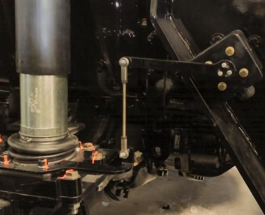
1. GENERAL SAFETY INSTRUCTIONS
Operators must read, understand and be aware of these general safety instructions. Before operating vehicle a full inspection
must be done to ensure that all equipment and its safety equipment are available and work properly. You will find in this manual a
number of alert messages, please take time to read and follow them. They are there to protect you and to avoid any costly damaged
to your vehicle.
There are 7 warning lights in truck cab to warn you when something needs attention.

          •     3 warning lights: when suspension low oil level warning; Rear suspension return filter clogging warning; Rear
                Suspension filter clogging warning

          •     2 warning lights: Dump body low oil level warning when there is clogging in dump body return filter as well as
                suspension pressure and return filters. Special note about dump body filter light. It is normal that it turns on while
                body is coming down. This is caused by backpressure in the system due to high flow and doesn’t mean filter is clogged.
                It indicates filter clogging when it turns on as soon as PTO is engaged (after successful leveling)

          •     1 warning light: Rear Suspension error warning; Rear suspension pressure filter clogging warning.

          •     1 warning light for proper dump body position (It is normal that this warning light turns on when dumping). This is
                light labelled « rear suspension disabled”. It will come on as soon as dump body starts lifting and won’t come off until
                dump body is back down on frame. When this light is on, rear suspension stops any adjustments for safety reasons

If any of these warning lights come on, it is important to check and apply the corrective action as soon as possible. Refer to
troubleshooting section or OEM manuals.

        AVOID MOVING THE TRUCK WHEN THE DUMP BODY IS RAISED!

        DO NOT EXCEED THE MAXIMUM VEHICLE GROSS WEIGHT RATING (GVWR)!

     WHEN THE DUMP BODY IS RAISED FOR MAINTENANCE OR REPAIRS, IT MUST BE SECURED SO THAT IT CANNOT FALL
DOWN. FAILURE TO APPLY THIS PRECAUTION CAN RESULT IN SERIOUS INJURY OR DEATH!

        DRIVER MUST OPERATE AT PROPER SPEED ACCORDING TO ROAD AND GROUND CONDITIONS.

MU-03-01_D55T_Standard operating Maintenance Manuals (Mack)_201180220
                                           Copyright © 2018 - Dramis International Ltd, Baie-Saint-Paul, Qc Canada
  All rights reserved. Reproduction in whole or in part is prohibited without the written consent of the copyright owner.           4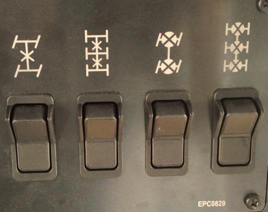
1. GENERAL OPERATING DESCRIPTIONS
     1.1.       DTS Hydro Pneumatic Dynamic Truck Suspension
There are two rocker switches for rear suspension function.

The rocker switch labelled Up/Down is used to raise or lower the suspension height and to adjust suspension
height at stand still or low speed. From normal operating height this operation will raise or lower the vehicle no
more than ± 4 inches. Suspension will automatically go back to operating ride height when vehicle speed reaches
10 Km/h.

The rocker switch labelled Operating Ride Height Level is used to bring the suspension back to normal operating
ride height after any change to ride height using the up/down rocker switch.
To readjust suspension height, press and maintain the operating ride height rocker switch until long beep
notification warning is heard.

Figure 1 : Position rocker switch                 Figure 2 : Ride height position                    Figure 3 : Down position

In all cases, when the vehicle reaches 10km/h, the suspension will automatically go back to normal operating ride height.

2.1.1 Maximum Speed

       Adopt vehicle speed according to the road conditions and in accordance with payload. The vehicle GVWR
is 81801Kg /180340lbs *; speed should not exceed 50Km/h laden and 80-Km/h unladen and should be reduced
depending on road and / or weather conditions.

*GVWR for Mack GU813 is displayed inside driver side door on compliance label

      In order to avoid engine over speed and to prevent overheating brakes, reduce vehicle speed to a minimum
before descending hill and if possible use engine brake or transmission retarder.

MU-03-01_D55T_Standard operating Maintenance Manuals (Mack)_20160408
                                       Copyright © 2016 - Dramis International Ltd, Baie-Saint-Paul, Qc Canada
 All rights reserved. Reproduction in whole or in part is prohibited without the written consent of the copyright owner.        5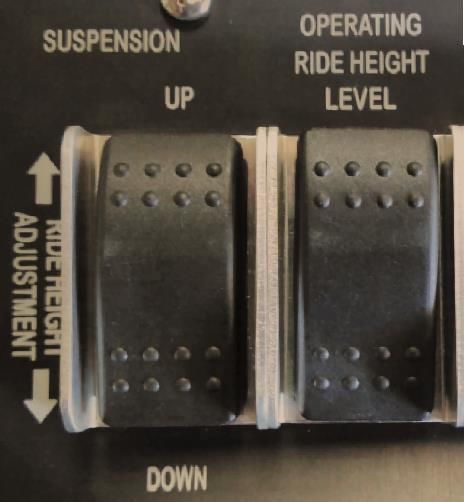
2.1.2 Maximum PayLoad (weight)

The recommended maximum load is 55 metric tons / 55000kg / 121254LBS /60627 tons (US). Do not overload
the Dump body. Make sure vehicle is in a stable ground before loading and that material is evenly distributed in
the body. Failure to follow this recommendation will void warranty.

           The vehicle may be unstable and damages can be caused to hydraulic and / or mechanical
components if the load exceeds maximum payload of 55 metric tons/55000kg/121254LBS/60.627 US tons.

MU-03-01_D55T_Standard operating Maintenance Manuals (Mack)_201180220
                                       Copyright © 2018 - Dramis International Ltd, Baie-Saint-Paul, Qc Canada
All rights reserved. Reproduction in whole or in part is prohibited without the written consent of the copyright owner.   6
2.1.3 Leveling Limitations

During unloading process, the Maximum lateral grade should be 7 degrees or less. If the slope is greater than 7
degrees a warning alarm (beep) will be heard and the suspension will not level out.

            NOTE: MAXIMUM longitudinal slopes for unloading is ± 5 °

2.1.4 Road grade

Under ideal road conditions, the vehicle load is designed to operate on a maximum grade of 20%. Operation on
grades greater than 20% is not recommended and will void warranty.

                Maximum Tilt Specifications

You must have proper and appropriate overhead clearance before dumping.

2.1.5 Dump Body Unloading Procedure

     1.   Stop the vehicle
     2.   Engage parking brakes.
     3.   Engage PTO – Vehicle cannot be in movement
     4.   Once the PTO is engaged, if the ground has an inclination the suspension leveling process will begin. There will be a
          ± 5 seconds delay before the Dump body begins to rise.

     5.                  Once the Dump body is lifted it’s very important to limit the movement of the vehicle, because the
          suspension is no longer laterally stabilized. If the truck is moved during unloading, there is a very high risk of roll
          over! If you have no choice and need to move the vehicle release slowly the service brake. Again, moving the truck
          while the Dump body is raised is an extremely dangerous maneuver! If you have to move the vehicle, use very slow
          speed and avoid sudden maneuvers.
     6.   When Dump body is completely empty apply brakes gently and lower the Dump body.

     7.           It is important that the Dump body has been completely lowered onto the truck chassis before you move
          the vehicle. If not, a warning alarm will turn on.

MU-03-01_D55T_Standard operating Maintenance Manuals (Mack)_20160408
                                       Copyright © 2016 - Dramis International Ltd, Baie-Saint-Paul, Qc Canada
 All rights reserved. Reproduction in whole or in part is prohibited without the written consent of the copyright owner.      7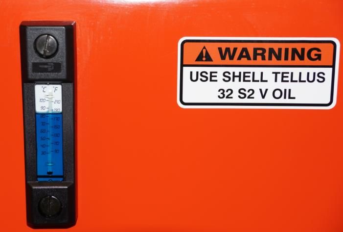
Command and control of dump body unloading

Body cannot be lifted unless PTO is engaged. If lateral grade is higher than 7deg, suspension will not be able to level,
suspension error light will come on and PTO will not engage. During leveling operation a warning sound will be heard.
Operator must then reposition truck and try leveling suspension once again before dump operation.

2.1.6 Adjusting Ride Height

To ease loading and/or vehicle maintenance you can use this option by activating the Up/Down button to adjust the height
of the vehicle. From normal operating height this operation will raise or lower the vehicle no more than ± 4 inches. The height
will set back to normal operating position automatically when the truck reaches 10 km/h. It can also be done manually by
holding the Operating Ride Height button.
     ➢ Refer to Rear Suspension on page 3 for detailed instructions.

2.1.7 Operating Ride Height Procedure

This operation is to bring the vehicle back to normal suspension ride height. This operation is done automatically when the
truck reaches 10km/h. It can also be done manually by pushing the Ride Height adjustment button down until long beep
notification warning is heard.
     ➢ Refer to Rear Suspension on page 3 for detailed instructions.

REFER TO SCHEDULE 8.2 FO FULL DTS OPERATING AND MAINTENANCE

MU-03-01_D55T_Standard operating Maintenance Manuals (Mack)_20160408
                                       Copyright © 2016 - Dramis International Ltd, Baie-Saint-Paul, Qc Canada
 All rights reserved. Reproduction in whole or in part is prohibited without the written consent of the copyright owner.    8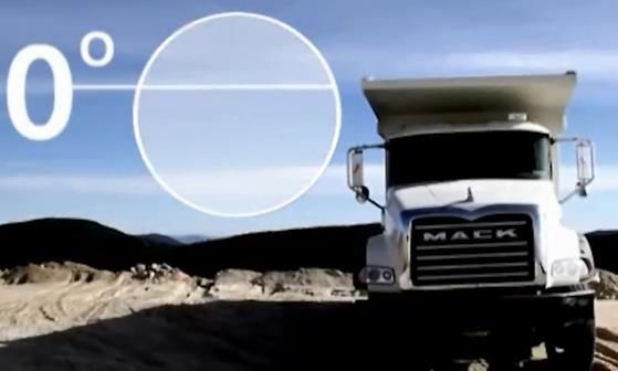
3. MAINTENANCE AND BREAK-IN GUIDELINES
Although your DRAMIS truck has been thoroughly inspected during its production process, special care must be
taken during the break-in period common to any new equipment. Perform the following inspection points during
the vehicle’s first 600 operating hours. (Ref. to Preventive maintenance – MU-03-22 D150T Preventive
Maintenance)
The hydraulic system on rear suspension is always in high pressured mode even if the truck engine has
been shut off for several hours/days. See pressure release procedure below. Failure to follow pressure release
procedure may result in serious injury and even death.
Pressure release procedure
Even though engine is turned off, there is always pressure in the rear suspension hydraulic system. Below is the
procedure to relief pressure in the system when required (in order to change a hose for example).
Start the engine and lower the suspension on spacer blocks or all the way to the bump stops using the ride height
adjustment rocker switch “down” function. Keep holding the rocker switch in “down” position for three minutes
maximum after suspension has reached blocks on bump stops. This will relief most of the pressure in the system
but there will still be some residual pressure.
To relief the residual pressure, slowly loosen hose fitting on one of the rear suspension accumulators while
keeping a container close to collect the oil that will leak out. Repeat on corresponding accumulator on opposite
side. System is now completely relieved of any pressure and it is now safe to work on it.
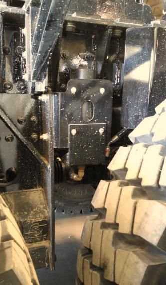
Figure 4 : Rear suspension accumulator (15 bar)
MU-03-01_D55T_Standard operating Maintenance Manuals (Mack)_20160408
Copyright © 2016 - Dramis International Ltd, Baie-Saint-Paul, Qc Canada
All rights reserved. Reproduction in whole or in part is prohibited without the written consent of the copyright owner. 9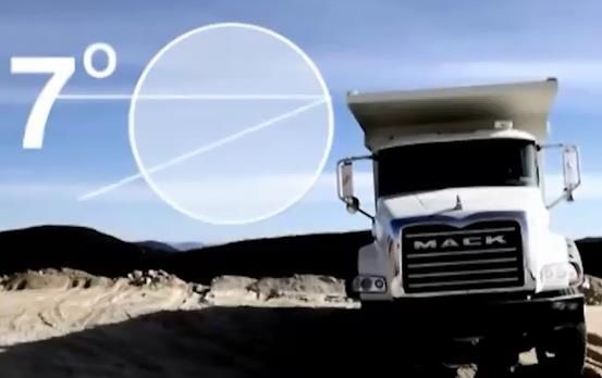
3.1 Break in schedule

Refer to support document Service Tables T1-Break-in (Document # MU-03-22 D55T_Service Tables)
The following service tables are also available:
                        TABLE #                                         DESCRIPTION
 T1 – Break In                                         FRONT AND REAR SUSPENSION BREAK-IN PERIOD
                                                       SCHEDULE
 T1- A Preventive Maintenance                          PREVENTIVE MAINTENANCE
 T1- B Predictive Maintenance                          PREDICTIVE MAINTENANCE
 T2- AMS50THD Front                                    FRONT TWIN STEER PREVENTIVE MAINTENANCE

MU-03-01_D55T_Standard operating Maintenance Manuals (Mack)_20160408
                                       Copyright © 2016 - Dramis International Ltd, Baie-Saint-Paul, Qc Canada
All rights reserved. Reproduction in whole or in part is prohibited without the written consent of the copyright owner.   10
3.2 OIL LEVEL CHECK PROCEDURES
Dump body Vehicle must be level and dump body must be completely lowered to check oil level.
DTS HYDRO PNEUMATIC DTS SUSPENSION
DRAMIS uses a maintenance free rear suspension, however it is important to check daily for any apparent damage or oil
leakage.
To check suspension oil level vehicle must be level and suspension must be at Operating Ride Height.
See Operating ride height procedure. SEE SECTION 2.1
MU-03-01_D55T_Standard operating Maintenance Manuals (Mack)_20160408
Copyright © 2016 - Dramis International Ltd, Baie-Saint-Paul, Qc Canada
All rights reserved. Reproduction in whole or in part is prohibited without the written consent of the copyright owner. 11Hydraulic oil interchange
As delivered by DRAMIS, oil in dump body system is Shell Tellus 32 S2 V and oil in DTS suspension system is
Mobil Univis HVI 26. These specific oil brand must be used for oil fill up or replacement. You must validate
with DRAMIS before changing to any other oil brand in either systems. Failure to do so will void warranty and
could potentially lead to damage.
Oil filter specification
The vehicle is equipped with clogging light indicator in the cab. If the warning light indicator turns on, filter must be
replaced immediately. When replacing filter elements be sure to use authorized equivalent if OEM replacement part if not
available. We highly recommend using OEM replacement filter elements.
• 2 warning lights when there is clogging in dump body return filter as well as suspension pressure and return
filters. Special note about dump body filter light. It is normal that it turns on while body is coming down. This
is caused by backpressure in the system due to high flow and doesn’t mean filter is clogged. It indicates filter
clogging when it turns on as soon as PTO is engaged (after successful leveling)
RECOMMENDED FILTERS:
SYSTEM TYPE FILTER SPECS
Microglass element with 5 micron β1000 efficiency and rated for at
DTS Rear Suspension Pressure
least 10 gpm flow and 5000psi rated pressure
Microglass element with 7 micron β1000 efficiency and rated for at
DTS Rear Suspension Return
least 10 gpm flow
Microglass element with 5 micron β1000 efficiency and rated for at
Dump bodies Return
least 120 gpm flow
Table 1 : Recommended filters
MU-03-01_D55T_Standard operating Maintenance Manuals (Mack)_20160408
Copyright © 2016 - Dramis International Ltd, Baie-Saint-Paul, Qc Canada
All rights reserved. Reproduction in whole or in part is prohibited without the written consent of the copyright owner. 123.3 Hydraulic Suspension good practices
The hydraulic system is very sensitive to contaminants/dirt in oil that could create system malfunction. A
contaminated system is very hard to clean and care must be taken to always follow these good practices:
• Always insure clean workspace and area before maintenance and repair
• If a hydraulic hose (or pipe) has to be replaced, only use hydraulic hose that has been cleaned using
an Ultraclean type system and plugged at each end. Remove plugs only when installing on truck
• Same as above applies to valves and manifolds. Never leave a port open to environment. Plug
until hose can be installed back;
• Hydraulic reservoirs are pressurized through the truck pneumatic system which ensures only clean
air gets into them. This system should be inspected for proper operation on a regular basis.
• Breather(s) on the oil reservoirs are part of the pressurization feature and should be replaced if
leakage occurs.
• Oil and filters should be replaced at recommended intervals or whenever a contamination event
occurs. At the same time, reservoirs should be cleaned.
• Work must not be performed outside of clean work space.
3.4. Sisu front and rear drive axles
The Sisu axles on this truck are rated to 23000kg at the front (11500
kg each axle) and 60000kg at the rear (20000kg each axle). Exceeding
these capacities will void warranty and could potentially lead to
damage.
Rocker switches in figure 28, available on the dashboard, enable
operator to lock or unlock the wheel differentials and inter axle
differentials.
Wheel differentials and inter axle differentials can be locked only in
case of inability to move the truck.
Picture 5 : Rocker switches to lock or unlock
differentials and inter axles
Turning when wheel and inter-axle differentials are locked could damage the axles. These functions
should be used only over a short distance.
MU-03-01_D55T_Standard operating Maintenance Manuals (Mack)_20160408
Copyright © 2016 - Dramis International Ltd, Baie-Saint-Paul, Qc Canada
All rights reserved. Reproduction in whole or in part is prohibited without the written consent of the copyright owner. 13Oil in axle’s differentials and planetaries wheel hubs is Petro-Canada, Traxon E, 75W140 synthetic. This specific
oil brand must be used for oil fill up or replacement. You must validate with DRAMIS before changing to any
other oil brand.
Failure to do so will void warranty and could potentially lead to damage.
Refer to MU-03-31 SISU Maintenance manual
MU-03-01_D55T_Standard operating Maintenance Manuals (Mack)_20160408
Copyright © 2016 - Dramis International Ltd, Baie-Saint-Paul, Qc Canada
All rights reserved. Reproduction in whole or in part is prohibited without the written consent of the copyright owner. 144. Maintenance
4.1 PREVENTIVE
For every sub-system that DRAMIS has added to the base chassis, please refer to preventive maintenance MU-
03-22 D150T Preventive Maintenance (A-150h; B- 300h; C-600H) which indicates specific maintenance intervals
and requirements. Dramis preventive maintenance excludes the chassis, Sisu drive axles, Namco Transfer case,
Fire suppressor, Automatic lubrication system OEM maintenance & service schedules.
Inspection check list – in order to track maintenance tasks please refer and use the DRAMIS inspection check list
for each maintenance interval. Copy of these check lists must be retained for warranty and repair tracking of
each unit.
Please follow base preventive maintenance list below in order to maximize life expectancy of all your suspension
components.
• Every week:
o Apply grease on drive shafts, steering column and U-joint grease points.
▪ Note: There is a multi-point automatic greasing system for all other components
(Suspensions, Axles, etc.).
o Check for any excessive or uneven tire wear. Inspect steering system and components. Have
alignment performed at first signs of excessive or uneven tire wear.
Refer to AMS50THD Twin Steer Workshop Manual & alignment guidelines
MU-03-01_D55T_Standard operating Maintenance Manuals (Mack)_20160408
Copyright © 2016 - Dramis International Ltd, Baie-Saint-Paul, Qc Canada
All rights reserved. Reproduction in whole or in part is prohibited without the written consent of the copyright owner. 15Alignment
4. FRONT TWIN STEER ALIGNMENT
Front twin steer axle alignment is required every time a steering component is replaced or an event requiring loosening of axle
U-bolts is performed, and on any of the steering axles.
As noted in the preventive maintenance section, alignment must be performed at first signs of uneven or excessive tire wear.
Important alignment notes: Alignment cannot be performed if steering components are loose or damaged
During alignment procedure, it is important to make sure that the mechanical steering stops are well synchronized
between both axles as well as with the hydraulic assist system relief valve. Bad synchronization of mechanical steering stops is a
major cause of premature wear on steering components and may potentially result in the failure of critical parts to the safe
operation of the vehicle.
Figure 6 : Axle stopper Figure 7 : Front twin steer alignment diagram
During alignment procedure, all tires, (front and rear) must be on the same level so that the twin steer equalizer beam is in a level
position (see drawing). Use blocks when needed. Failure to follow this requirement will result in bad alignment that could
potentially cause premature tire wear and erratic vehicle behavior. The above also applies when using turn-tables that are
integrated in the floor under one of the two axles.
Please refer to Workshop manual for complete information on maintenance of AMS50THD
MU-03-01_D55T_Standard operating Maintenance Manuals (Mack)_20160408
Copyright © 2016 - Dramis International Ltd, Baie-Saint-Paul, Qc Canada
All rights reserved. Reproduction in whole or in part is prohibited without the written consent of the copyright owner. 16Alignment
5. Trouble shooting
Product ID Trouble Diagnostic Solution
AMS50THD
TWIN STEER
Not working Warning light is ON. Call DRAMIS After Sales Service.
Not working Oil level to low. (Warning light is ON) Add oil (Mobil UNIVIS HVI 26)
Not working / Tighten or replace damaged hose /
Hydraulic leak / hose failure.
Malfunction coupling.
Check if restriction in suction hose
Malfunction Noisy hydraulic pump or damaged.
otherwise Call DRAMIS After Sales Service.
Replace fuse – If it burns again call DRAMIS
Not working Burned fuse.
After Sales Service.
« Whenever one of the following
components (DTS pump and suspension
manifolds, DTS pump, DTS ECM, DTS
DTS Hydro
height or level sensors) are changed,
Pneumatic
system calibration is required. Please
Suspension
Not working Improper rear sensor adjustment. contact Simard I order to get
Commissioning DTS procedure and
determine what steps of that
procedure need to be performed
depending on components changed.”
Check oil level or Call DRAMIS After Sales
Not working Fault code. (Warning light is on)
Service.
Move vehicle to proper level 7degrees or
Not working Ground level is over 7 degrees when dumping.
less.
Clean circuit and components and replace
Malfunction Contaminant in height or pump control manifold.
oil filters.
Add oil – Univis HVI 26Shell Tellus 32 or
Malfunction Oil level to low.
Chevron AW32
Malfunction Dump body is overloaded. Reduce weight in Dump body.
Dump body position, improper proximity switches Adjust sensor – See adjustment procedure
Malfunction
adjustment. PENDING
Move vehicle to proper level 7degrees or
Not working Ground level is over 7 degrees when dumping.
less.
Dump body Check if hydraulic tank is pressurized
Malfunction
& Telescopic between 3-5 PSI
Hydraulic pump.
cylinder Check if there is any restriction in suction
Not working
hose and/or valves.
Clean circuit and components and replace oil
Not working Contaminant in hydraulic circuit.
filters.
Malfunction Check for any hydraulic leaks.
Telescopic cylinder. Check for oil leak or if any damage on
Not working
cylinder.
Not working Spool valve malfunction. Check for any obstruction in air system.
MU-03-01_D55T_Standard operating Maintenance Manuals (Mack)_20160408
Copyright © 2016 - Dramis International Ltd, Baie-Saint-Paul, Qc Canada
All rights reserved. Reproduction in whole or in part is prohibited without the written consent of the copyright owner. 17Make sure that air pressure is at least 70
PSI or more.
Cables tensions have to be the same.
Tension on door swivel must be identical
Check if both cables are attached with cable
Malfunction clamps. There must be equal tension
Automatic Tail gate system.
between automatic door cables on
each side
Not working
MU-03-01_D55T_Standard operating Maintenance Manuals (Mack)_20160408
Copyright © 2016 - Dramis International Ltd, Baie-Saint-Paul, Qc Canada
All rights reserved. Reproduction in whole or in part is prohibited without the written consent of the copyright owner. 18WARRANTY
Warranty coverages
DRAMIS OEM MONTHS ENGINE PARTS SHOP NOTES
WARRANTY HOURS WORK
COVERAGE
Front Twin Simard 24 4000 100% 100%
Steer Suspensions
Suspension
(AMS50THD)
Rear Hydro Simard 24 4000 100% 100%
Pneumatic Suspensions
Suspension & VSE
(DTS)
HD DUMP Dramis 24 4000 100% 100%
BODY
Body Only Bibeau 12 n/a 100% Workmanship defects
G2 Mailhot 24 n/a 100% Manufacturing defects
Telescopic and materials
Hoist
MU-03-01_D55T_Standard operating Maintenance Manuals (Mack)_20160408
Copyright © 2016 - Dramis International Ltd, Baie-Saint-Paul, Qc Canada
All rights reserved. Reproduction in whole or in part is prohibited without the written consent of the copyright owner.
19WARRANTY
6. D55T-10x6 Technical Support documents
The following support documents are available to customer by access to secured FTP site. Please
contact Dramis for user name and password authorization to access the following documents.
SYSTEM DESCRIPTION Doc. # NAME
(CATEGORY)
OPERATING MU-03-01 D55T_Standard Operating Maintenance
MANUAL Manual
D55T General Parts MU-03-02 HX620 AMS50THD2+DTS-M92-ASY
Spare parts MU-03-03 D55T_Spare Parts List
Torques MU-03-11 DTS-Tightening torque charter
Service tables MU-03-22 D55T_Service_Tables_V.1.2
DTS – REAR User manual MU-03-04 DTS_Dramis_User-Manual_A12491.0.01.C
SUSPENSION
Electrical MU-03-05 A09914.0.01.E Electronic diagram
diagram (VSE)
Hydraulic MU-03-06 XXD-352-03_P2 DTS Hydraulic diagram
diagram (Dramis
Hydraulic MU-03-25 A10178.0.02.G Hydraulic diagram
diagram (VSE)
Oil approval list MU-03-07 DTS oil approval list
(VSE)
Cylinder MU-03-08 A10336.6.01.B_EN Installation DTS HD
Installation cylinder
Manual (VSE)
Hyd. cylinder MU-03-09 Commissioning instruction DTS_VSE
adjustment
Dump Body Electrical MU-03-10 XXD-351_12_Console Electrical diagram
diagram MU-03-10 XXD-351_13 Dump body & Diff. Lights
electrical diagram
OEM Parts MU-03-12 Dump_Body_Parts_Manual-MPBMEA-C
manual
Oil specs MU-03-13 Data_Sheet_Shell_Tellus_S2_V_32
Proximity MU-03-14 Proximity sensor setting procedure
sensor
Hydraulic MU-03-15 XXD-351-03_Dump Hydraulic diagram
diagram
Cylinder user MU-03-16 Mailhot User Guide G2-235-8.7-5A REV 1
manual (Mack)
Cylinder parts MU-03-17 Mailhot_PG0762355HG0106_4
Cylinder Seal kit MU-03-18 Mailhot_Seal_Kit_Parts_List_UI47G0765_1
parts
MU-03-01_D55T_Standard operating Maintenance Manuals (Mack)_20160408
Copyright © 2016 - Dramis International Ltd, Baie-Saint-Paul, Qc Canada
All rights reserved. Reproduction in whole or in part is prohibited without the written consent of the copyright owner.
20Brake system MU-03-26 XXD-03-26 Mack
Pneumatic_Pneumatic_Brake_System diagram
Air Tanks
MU-03-27 PM16_Eng_Mack_ Pneumatic_Brake-System
Diagram
DEL lights MU-03-28 DEL_light_wiring_XXD-351_06_Mack
SISU MU-03-31 SISU AXLE MAINTENANCE MANUAL
MU-03-01_D55T_Standard operating Maintenance Manuals (Mack)_20160408
Copyright © 2016 - Dramis International Ltd, Baie-Saint-Paul, Qc Canada
All rights reserved. Reproduction in whole or in part is prohibited without the written consent of the copyright owner.
21You can also read