Product specification - IRB 360 - Leobotics
←
→
Page content transcription
If your browser does not render page correctly, please read the page content below
ROBOTICS

Product specification
IRB 360

Trace back information:
Workspace 21A version a11
Checked in 2021-03-19
Skribenta version 5.4.005
Product specification
                         IRB 360-1/1130
                         IRB 360-3/1130
                         IRB 360-8/1130
                         IRB 360-1/1600
                         IRB 360-6/1600
                                     OmniCore

             Document ID: 3HAC079010-001
                                    Revision: A

© Copyright 2020 -2021 ABB. All rights reserved.
 Specifications subject to change without notice.
The information in this manual is subject to change without notice and should not
be construed as a commitment by ABB. ABB assumes no responsibility for any errors
that may appear in this manual.
Except as may be expressly stated anywhere in this manual, nothing herein shall be
construed as any kind of guarantee or warranty by ABB for losses, damage to persons
or property, fitness for a specific purpose or the like.
In no event shall ABB be liable for incidental or consequential damages arising from
use of this manual and products described herein.
This manual and parts thereof must not be reproduced or copied without ABB's
written permission.
Keep for future reference.
Additional copies of this manual may be obtained from ABB.
Original instructions.
© Copyright 2020 -2021 ABB. All rights reserved.
Specifications subject to change without notice.Table of contents
Table of contents
Overview of this specification .......................................................................................................... 7
1 Description 9
1.1 Structure ......................................................................................................... 9
1.1.1 Introduction to structure ........................................................................... 9
1.1.2 Different robot version .............................................................................. 11
1.1.3 Definition of version designation ................................................................ 12
1.2 Safety standards ............................................................................................... 14
1.2.1 Applicable standards ............................................................................... 14
1.3 Installation ....................................................................................................... 16
1.3.1 Introduction to installation ......................................................................... 16
1.3.2 Operating requirements ............................................................................ 17
1.3.3 Mounting the manipulator ......................................................................... 18
1.4 Load diagrams .................................................................................................. 22
1.4.1 Introduction to load diagrams .................................................................... 22
1.4.2 Load diagrams ........................................................................................ 23
1.4.3 Hose set mounted on the manipulator arms ................................................. 30
1.4.4 Mechanical interface ................................................................................ 31
1.5 Maintenance and troubleshooting ......................................................................... 34
1.5.1 Introduction to maintenance and trouble shooting ......................................... 34
1.6 Robot motion .................................................................................................... 35
1.6.1 Introduction to robot motion ...................................................................... 35
1.6.2 Performance according to ISO 9283 ............................................................ 37
1.6.3 Acceleration ........................................................................................... 39
1.7 Typical cycle times ............................................................................................ 40
1.7.1 Introduction to typical cycle times .............................................................. 40
2 Specification of variants and options 41
2.1 Introduction to variants and options ...................................................................... 41
2.2 Manipulator ...................................................................................................... 42
2.3 Floor cables ..................................................................................................... 44
3 Accessories 45
3.1 Introduction to accessories ................................................................................. 45
Index 47
Product specification - IRB 360 5
3HAC079010-001 Revision: A
© Copyright 2020 -2021 ABB. All rights reserved.This page is intentionally left blank
Overview of this specification

Overview of this specification
About this product specification
                    This product specification describes the performance of the manipulator or a
                    complete family of manipulators in terms of:
                             •   The structure and dimensional prints
                             •   The fulfilment of standards, safety, and operating equipment
                             •   The load diagrams, mounting or extra equipment, the motion, and the robot
                                 reach
                             •   The specification of available variants and options
                        The specification covers the manipulator using the OmniCore controller.

Usage
                        Product specifications are used to find data and performance about the product,
                        for example to decide which product to buy. How to handle the product is described
                        in the product manual.
                        The specification is intended for:
                             •   Product managers and product personnel
                             •   Sales and marketing personnel
                             •   Order and customer service personnel

References

                        Reference                                                                     Document ID
                        Product specification - OmniCore C line                                       3HAC065034-001

                        Product manual - IRB 360                                                      3HAC030005-001

                                   Tip

                         All documents can be found via myABB Business Portal, www.abb.com/myABB.

Revisions
                        Revision              Description
                        A                     First edition.

Product specification - IRB 360                                                                                     7
3HAC079010-001 Revision: A
                                         © Copyright 2020 -2021 ABB. All rights reserved.
This page is intentionally left blank
1 Description
1.1.1 Introduction to structure
1 Description
1.1 Structure
1.1.1 Introduction to structure
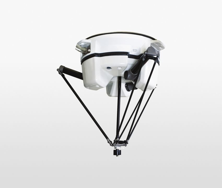
Robot family
The IRB 360 is ABB Robotics’ latest generation of high performance industrial
robots. Based on the famous IRB 340 robot family in a modular design. It is specially
designed for industries with a great need for flexible automation, such as pick and
place operations and assembly.The IRB 360 is extremely powerful with an
acceleration of up to 10 g’s, and a handling capacity of up to 8 kg. Thanks to
optimized drive-chains and ABB’s patented QuickMove TM functions it is the fastest
robot in its class, up to 200 picks per minute (defined by cycle and load).
Operating system
The robot is equipped with the OmniCore C30 controller and robot control software,
RobotWare. RobotWare supports every aspect of the robot system, such as motion
control, development and execution of application programs, communication etc.
See Operating manual - OmniCore.
Safety
Safety standards valid for complete robot, manipulator and controller.
Additional functionality
For additional functionality, the robot can be equipped with optional software for
application support - communication features - network communication - and
advanced functions such as multi-tasking, sensor control, etc. For a complete
description on optional software, see Product specification - OmniCore C line.
PickMaster ® Twin is a PC and robot controller based application software for vision
guided picking of random flow products on the fly. It is providing a task-oriented
programming and executions of fast pick and place operations performed up to
10 robots, see Product specification - PickMaster Twin.
Clean room robots
xx0900000435
The clean room robots are classified for room class 5 according to ISO 14644-1.
For options not selectable together with Clean Room, see Specification of variants
and options on page 41.
Continues on next page
Product specification - IRB 360 9
3HAC079010-001 Revision: A
© Copyright 2020 -2021 ABB. All rights reserved.1 Description
1.1.1 Introduction to structure
Continued
Washdown statement
All components for WashDown protection class have been found to comply with
USDA/FDA, Code of Federal Regulations Title 21 regarding choice of material,
material behavior, and sanitary operations, as per 31 December 2007. Changes in
the USDA/FDA regulations will be incorporated in the specification when
appropriate. (Relevant chapters of CFR are part 100-199). The intended use is
incidental food contact. Any gripper to be used must be investigated separately.
Manipulator axes
Axis 2
Axis 1
Axis 3
Axis 4
xx0900000412
10 Product specification - IRB 360
3HAC079010-001 Revision: A
© Copyright 2020 -2021 ABB. All rights reserved.1 Description
1.1.2 Different robot version
1.1.2 Different robot version
Robot types
The following different standard robot types are available:
Robot type Handling capacity (kg)
IRB 360-1/1130 1 kg
IRB 360-3/1130 3 kg
IRB 360-8/1130 8 kg
IRB 360-1/1600 1 kg
IRB 360-6/1600 6 kg
Product specification - IRB 360 11
3HAC079010-001 Revision: A
© Copyright 2020 -2021 ABB. All rights reserved.1 Description
1.1.3 Definition of version designation
1.1.3 Definition of version designation
Weight
Manipulator Weight
Standard 120 kg
Wash Down
Other technical data
Data Description Note
Airborne noise level The sound pressure level < 70 dB (A) Leq (acc. to Machinery
outside the working space directive 2006/42/EG)
Power consumption at max load
Type of movement IRB 360/1
Typical pick - and - place 0.477 kW
cycle with 1 kg payload
Continues on next page
12 Product specification - IRB 360
3HAC079010-001 Revision: A
© Copyright 2020 -2021 ABB. All rights reserved.1 Description
1.1.3 Definition of version designation
Continued
IRB 360-1, IRB 360-3, 360-8, 360-1/800, IRB 360-1/1600 and IRB 360-6/1600
69
(A)
(B)
R483,5 IRB 360/1(3) 1130
(C)
R 720 IRB 360/1 1600
R 375 IRB 360/8 1130
R 600 IRB 360/6 1600
R
R
37
0
120 ° 36°
0°
12
12
0°
xx0900000411
Robot variant A B C R
IRB 360-1/800 960 200 - 400
IRB 360-1/1130 865 250 50 565
IRB 360-3/1130 865 250 50 565
IRB 360-8/1130 892 250 100 565
IRB 360-1/1600 1112 300 50 800
IRB 360-6/1600 1107.5 305 155 800
Product specification - IRB 360 13
3HAC079010-001 Revision: A
© Copyright 2020 -2021 ABB. All rights reserved.1 Description
1.2.1 Applicable standards
1.2 Safety standards
1.2.1 Applicable standards
Note
The listed standards are valid at the time of the release of this document. Phased
out or replaced standards are removed from the list when needed.
General
The product is designed in accordance with ISO 10218-1:2011, Robots for industrial
environments - Safety requirements -Part 1 Robots, and applicable parts in the
normative references, as referred to from ISO 10218-1:2011. In case of deviations
from ISO 10218-1:2011, these are listed in the declaration of incorporation which
is part of the product delivery.
Normative standards, ISO
Standard Description
ISO 9283:1998 Manipulating industrial robots - Performance criteria and related
test methods
ISO 10218-2 Robots and robotic devices - Safety requirements for industrial
robots - Part 2: Robot systems and integration
ISO 12100 Safety of machinery - General principles for design - Risk as-
sessment and risk reduction
ISO 13849-1:2006 Safety of machinery - Safety related parts of control systems
- Part 1: General principles for design
ISO 13850 Safety of machinery - Emergency stop - Principles for design
IEC 60204-1:2005 Safety of machinery - Electrical equipment of machines - Part
1: General requirements
IEC 62061:2005 Safety of machinery - Functional safety of safety-related elec-
trical, electronic and programmable electronic control systems
Region specific standards and regulations
Standard Description
ANSI/RIA R15.06 Safety requirements for industrial robots and robot systems
ANSI/UL 1740 Safety standard for robots and robotic equipment
CAN/CSA Z 434-14 Industrial robots and robot Systems - General safety require-
ments
Other standards used in design
Standard Description
ISO 9787:2013 Robots and robotic devices -- Coordinate systems and motion
nomenclatures
IEC 61000-6-2 Electromagnetic compatibility (EMC) – Part 6-2: Generic
standards – Immunity standard for industrial environments
Continues on next page
14 Product specification - IRB 360
3HAC079010-001 Revision: A
© Copyright 2020 -2021 ABB. All rights reserved.1 Description
1.2.1 Applicable standards
Continued
Standard Description
IEC 61000-6-4 Electromagnetic compatibility (EMC) – Part 6-4: Generic
(option 129-1) standards – Emission standard for industrial environments
ISO 13732-1:2008 Ergonomics of the thermal environment - Part 1
IEC 60974-1:2012 i Arc welding equipment - Part 1: Welding power sources
IEC 60974-10:2014 i Arc welding equipment - Part 10: EMC requirements
ISO 14644-1:2015 ii Classification of air cleanliness
IEC 60529:1989 + A2:2013 Degrees of protection provided by enclosures (IP code)
i Only valid for arc welding robots. Replaces IEC 61000-6-4 for arc welding robots.
ii Only robots with protection Clean Room.
Product specification - IRB 360 15
3HAC079010-001 Revision: A
© Copyright 2020 -2021 ABB. All rights reserved.1 Description
1.3.1 Introduction to installation
1.3 Installation
1.3.1 Introduction to installation
General
Depending on robot version an end effector of max weight 1 to 8 kg including
payload, can be mounted on the robot mounting flange. See Load diagrams on
page 22. Other equipment, such as a hose, can be mounted on the upper and lower
arm, max weight 300g/m. See Hose set mounted on the manipulator arms on
page 30.
16 Product specification - IRB 360
3HAC079010-001 Revision: A
© Copyright 2020 -2021 ABB. All rights reserved.1 Description
1.3.2 Operating requirements
1.3.2 Operating requirements
Protection standards
Description Protection standard IEC529
Standard IP54
Wash Down IP67
Clean Room IP54
Clean room standards
Description Protection standard DIN ISO 14644
Standard Class 7
Clean Room Class 5
Stainless Clean Room Class 5
Explosive environments
The robot must not be located or operated in an explosive environment.
Ambient temperature
Description Standard/Option Temperature
Manipulator during opera- Standard 0°C i (+32°F) to +45°C (+113°F)
tion
For the controller Standard/Option Product specification - OmniCore C line
Complete robot during Standard -25°C (-13°F) to +55°C (+131°F)
transportation and stor-
age
i At low environmental temperature < 10 o C is, as with any other machine, a warm-up phase
recommended to be run with the robot. Below 5 o C this warm-up phase is mandatory. Otherwise
there is a risk that the robot stops or run with lower performance due to temperature dependent
oil- and grease viscosity.
Relative humidity
Description Relative humidity
Complete robot during transportation and stor- Max. 95% at constant temperature
age
Complete robot during operation Max. 95% at constant temperature
Product specification - IRB 360 17
3HAC079010-001 Revision: A
© Copyright 2020 -2021 ABB. All rights reserved.1 Description
1.3.3 Mounting the manipulator
1.3.3 Mounting the manipulator
General
Maximum load in relation to the base coordinate system. See Figure below.
Robot version IRB 360-1/800, IRB 360-1/1130, IRB 360-1/1600, IRB 360-3/1130
Force N Max. load in operation
Fx ±330 N
Fy ±260 N
Fz -1500 ±170 N
Torque Nm Max. load in operation
Mx ±200 Nm
My ±230 Nm
Mz ±100 Nm
Robot version IRB 360-8/1130, IRB 360-6/1600
Force N Max. load in operation
Fx ±550 N
Fy ±500 N
Fz -1500 ±460 N
Torque Nm Max. load in operation
Mx ±380 Nm
My ±440 Nm
Mz ±180 Nm
Robot frame is not included in the delivery.
Stiffness of robot frame
The stiffness of the robot frame must be designed to minimize the influence on the
dynamic behavior of the robot. It is recommended that a frame with a lowest natural
frequency (with the robot mounted in the frame) higher than 17 Hz is used for robot
versions IRB 360-1/1130, IRB 360-3/1130, IRB 360-1/1600 and a frame with a lowest
natural frequency higher than 40 Hz is used for robot version IRB 360-8/1130, IRB
360-6/1600. TuneServo can be used for adapting the robot tuning to a non-optimal
foundation.
Note
The working space is shown in the first figure in Robot motion on page 35.
Continues on next page
18 Product specification - IRB 360
3HAC079010-001 Revision: A
© Copyright 2020 -2021 ABB. All rights reserved.1 Description
1.3.3 Mounting the manipulator
Continued
en0900000413
The three support points of the manipulator base box shall be mounted against
three flat surfaces within the specification above. Shims is used if necessary.
Continues on next page
Product specification - IRB 360 19
3HAC079010-001 Revision: A
© Copyright 2020 -2021 ABB. All rights reserved.1 Description
1.3.3 Mounting the manipulator
Continued
Fastening the robot
B-B
xx0900000414
Position Description
A M12 screw
B Bonded seal washer, rubber/metal, if not a waterproof joint is required a plain
washer can be used
C Washer, EPDM-rubber, compressed 50%, If no need for waterproof joint is re-
quired you can disregard the rubber washer.
D Spacer, metal
E Robot frame
Continues on next page
20 Product specification - IRB 360
3HAC079010-001 Revision: A
© Copyright 2020 -2021 ABB. All rights reserved.1 Description
1.3.3 Mounting the manipulator
Continued
xx0900000415
Recommended screws for M12 x (50) 8.8 screw with yield strength 640 N/mm2 or
fastening the robot to the M12 x (50) screw A2-70 with yield strength 450N/mm2
frame
The length of the screws depend on the design of the robot
frame.
Torque value 70 Nm
Detection of collisions
The IRB 360 has a basic feature that can detect a collision. This is a system that
detects divergence between calculated and actual motor torques. The controller
can also stop the robot if load parameters are defined incorrectly, due to that the
moment of the torque deviates from the calculated. An advanced option that
includes the possibility to manually setting parameters is called Collision Detection.
For more detailed information see Product specification - OmniCore C line.
Product specification - IRB 360 21
3HAC079010-001 Revision: A
© Copyright 2020 -2021 ABB. All rights reserved.1 Description
1.4.1 Introduction to load diagrams
1.4 Load diagrams
1.4.1 Introduction to load diagrams
General
CAUTION
It is very important to always define correct actual load data and correct payload
of the robot. Incorrect definitions of load data can result in overloading of the
robot.
If incorrect load data and/or loads outside load diagram is used the following
parts can be damaged due to overload:
• motors
• gearboxes
• mechanical structure
CAUTION
Robots running with incorrect load data and/or with loads outside load diagram
will not be covered by the robot warranty.
22 Product specification - IRB 360
3HAC079010-001 Revision: A
© Copyright 2020 -2021 ABB. All rights reserved.1 Description
1.4.2 Load diagrams
1.4.2 Load diagrams
Note
The weight permitted for loads includes grippers etc.
The data types loaddata and tooldata with moment of inertia must be used!
IRB360-1/1130, IRB 360-1/1600 and IRB 360-1/800
Loads 0.1 kg, 0.5 kg and 1.0 kg:
xx0900000416
Description
Z See the above diagram and the coordinate system in Product specifica-
tion - OmniCore C line.
L Distance in X-Y plane from Z-axis to the mass center of gravity of the load.
tooldata Weight of the gripper (kg).
The center of gravity of the gripper (mm).
The moment of inertia of the gripper (kgm 2 ).
No value or wrong value may damage the robot.
For more information see Technical reference manual - RAPID Instructions,
Functions and Data types
Continues on next page
Product specification - IRB 360 23
3HAC079010-001 Revision: A
© Copyright 2020 -2021 ABB. All rights reserved.1 Description
1.4.2 Load diagrams
Continued
Description
loaddata Weight of the product (kg).
The center of gravity of the product (mm).
The moment of inertia of the product (kgm 2 ).
No value or wrong value may damage the robot.
For more information see Technical reference manual - RAPID Instructions,
Functions and Data types
For large off-sets in z-direction some combinations of Jo and movement of
robot requires use of RAPID commands AccSet and/or TuneServo to min-
imize vibration of tool. This applies for limited inherent gripper stiffness and
the backlash of the picked load, for example a shaking bag.
Note
Best possible performance of the IRB 360 is achieved when the gripper's
center of gravity is close to axis 4 (L= 0 mm in load diagram).
Jo=own moment of inertia of the total handle weight.
IRB360-3/1130
Load 1.0 kg - 3.0 kg
xx0900000419
Load diagram above is valid for Jo zz from 0 - 0.0212 kgm 2 .
Description
Z See the above diagram and the coordinate system in Product specifica-
tion - OmniCore C line.
L Distance in X-Y plane from Z-axis to the mass center of gravity of the load.
Continues on next page
24 Product specification - IRB 360
3HAC079010-001 Revision: A
© Copyright 2020 -2021 ABB. All rights reserved.1 Description
1.4.2 Load diagrams
Continued
Description
tooldata Weight of the gripper (kg).
The center of gravity of the gripper (mm).
The moment of inertia of the gripper (kgm 2 ).
No value or wrong value may damage the robot.
For more information see Technical reference manual - RAPID Instructions,
Functions and Data types
loaddata Weight of the product (kg).
The center of gravity of the product (mm).
The moment of inertia of the product (kgm 2 ).
No value or wrong value may damage the robot.
For more information see Technical reference manual - RAPID Instructions,
Functions and Data types
Max. allowed mass moments of inertia is Jo zz = 0.055 kgm 2 .
For increasing values of Jo zz the allowed L-offset of the center of gravity
decreases linearly from the values in load diagrams down to zero. For an
example of high inertia see diagram on next page.
For large off-sets in z-direction some combinations of Jo and movement of
robot requires use of RAPID commands AccSet and/or TuneServo to min-
imize vibration of tool. This applies for limited inherent gripper stiffness and
the backlash of the picked load, for example a shaking bag.
Note
Best possible performance of the IRB 360 is achieved when the gripper's
center of gravity is close to axis 4 (L= 0 mm in load diagram).
Jo=own moment of inertia of the total handle weight.
Figure below shows load diagrams for Jo zz = 0.04 kgm 2 .
xx1100000102
Continues on next page
Product specification - IRB 360 25
3HAC079010-001 Revision: A
© Copyright 2020 -2021 ABB. All rights reserved.1 Description
1.4.2 Load diagrams
Continued
IRB360-8/1130
Load 1.0 kg - 8.0 kg
250
1
200
3
150
6
Z (mm)
8 1
100
50
0
10
15
20
25
30
35
0
5
L (mm)
xx1200001391
Load diagram above is valid for Jo zz from 0 - 0.1kgm 2 .
Description
Z See the above diagram and the coordinate system in Product specifica-
tion - OmniCore C line.
L Distance in X-Y plane from Z-axis to the mass center of gravity of the load.
tooldata Weight of the gripper (kg).
The center of gravity of the gripper (mm).
The moment of inertia of the gripper (kgm 2 ).
No value or wrong value may damage the robot.
For more information see Technical reference manual - RAPID Instructions,
Functions and Data types
loaddata Weight of the product (kg).
The center of gravity of the product (mm).
The moment of inertia of the product (kgm 2 ).
No value or wrong value may damage the robot.
For more information see Technical reference manual - RAPID Instructions,
Functions and Data types
Continues on next page
26 Product specification - IRB 360
3HAC079010-001 Revision: A
© Copyright 2020 -2021 ABB. All rights reserved.1 Description
1.4.2 Load diagrams
Continued
Description
Max. allowed mass moments of inertia is Jo zz = 0.15 kgm 2 .
For large off-sets in z-direction some combinations of Jo and movement of
robot requires use of RAPID commands AccSet and/or TuneServo to min-
imize vibration of tool. This applies for limited inherent gripper stiffness and
the backlash of the picked load, for example a shaking bag.
Note
Best possible performance of the IRB 360 is achieved when the gripper's
center of gravity is close to axis 4 (L= 0 mm in load diagram).
Jo=own moment of inertia of the total handle weight.
IRB360-6/1600
Load 1.0 kg - 6.0 kg
250
1
200
3
150
6
Z (mm)
1
100
50
0
10
15
20
25
30
35
0
5
L (mm)
xx1300000861
Load diagram above is valid for Jo zz from 0 - 0.1kgm 2 .
Description
Z See the above diagram and the coordinate system in Product specifica-
tion - OmniCore C line.
L Distance in X-Y plane from Z-axis to the mass center of gravity of the load.
tooldata Weight of the gripper (kg).
The center of gravity of the gripper (mm).
The moment of inertia of the gripper (kgm 2 ).
No value or wrong value may damage the robot.
For more information see Technical reference manual - RAPID Instructions,
Functions and Data types
Continues on next page
Product specification - IRB 360 27
3HAC079010-001 Revision: A
© Copyright 2020 -2021 ABB. All rights reserved.1 Description
1.4.2 Load diagrams
Continued
Description
loaddata Weight of the product (kg).
The center of gravity of the product (mm).
The moment of inertia of the product (kgm 2 ).
No value or wrong value may damage the robot.
For more information see Technical reference manual - RAPID Instructions,
Functions and Data types
Max. allowed mass moments of inertia is Jo zz = 0.15 kgm 2 .
For large off-sets in z-direction some combinations of Jo and movement of
robot requires use of RAPID commands AccSet and/or TuneServo to min-
imize vibration of tool. This applies for limited inherent gripper stiffness and
the backlash of the picked load, for example a shaking bag.
Note
Best possible performance of the IRB 360 is achieved when the gripper's
center of gravity is close to axis 4 (L= 0 mm in load diagram).
Jo=own moment of inertia of the total handle weight.
Extra equipment mounted on the manipulator arms
xx0900000420
M1 Limitation lines for center of gravity for M1
M2 Limitation lines for center of gravity for M2
Continues on next page
28 Product specification - IRB 360
3HAC079010-001 Revision: A
© Copyright 2020 -2021 ABB. All rights reserved.1 Description
1.4.2 Load diagrams
Continued
The robot is tuned for the Vacuum system or medium sized hose (options). If one
of these options is used no extra load should be defined. If neither the vacuum
system nor the medium sized hose is chosen:
• and both M1 and M2 are less than 175 g each, the robot can run with full
performance and no extra load should be defined.
• and M1 is more than 175 g, an extra load should be defined in the load
definition. The extra load should be M1-175 g. Maximum extra load allowed
is 175 g (M1 max = 350g).
• and M2 is more than 175 g, an extra load should be defined in the load
definition. The extra load should be M2-175 g. Maximum extra load allowed
is 175 g (M2 max = 350 g).
• The extra load should be defined in TCP 0
Product specification - IRB 360 29
3HAC079010-001 Revision: A
© Copyright 2020 -2021 ABB. All rights reserved.1 Description
1.4.3 Hose set mounted on the manipulator arms
1.4.3 Hose set mounted on the manipulator arms
General
xx0900000422
30 Product specification - IRB 360
3HAC079010-001 Revision: A
© Copyright 2020 -2021 ABB. All rights reserved.1 Description
1.4.4 Mechanical interface
1.4.4 Mechanical interface
IRB 360-1/1130, IRB 360-3/1130, IRB 360-1/1600
xx0700000471
Position Description
A Free space, depth 6 mm
B R1/4”
C Ø 14 H8 depth 4 mm
D Key grip = width 22 mm height 5,5 mm
E Ø 25 h8 depth 6 mm
Continues on next page
Product specification - IRB 360 31
3HAC079010-001 Revision: A
© Copyright 2020 -2021 ABB. All rights reserved.1 Description
1.4.4 Mechanical interface
Continued
IRB 360-8/1130, IRB 360-6/1600
3x 120°
°
60 10 57.5
96
10
6H7
+0.2
3x 6.6 0
25H8
50 h8
4x M6 10 6
40
45°
4x 90°
xx1300000170
Continues on next page
32 Product specification - IRB 360
3HAC079010-001 Revision: A
© Copyright 2020 -2021 ABB. All rights reserved.1 Description
1.4.4 Mechanical interface
Continued
Interface without axis 4
IRB 360-1/1130, IRB 360-3/1130, IRB 360-1/800
3x 62 ±0,05
A
3x
3x R20
6x 4,20
1 20
3x 52
3x 45
0.3 A
°
38
3 P6 4
30°
0.3 A
0°
A 5x
6
3x 4
3x14 5°
3x 10 3x
45
3x 10
3x 4
3x 4
°
0,05 R1
0,05 B
B
0,05 B
30 H7
79
1,6
A
6
3x 7
SECTION A-A
en0900000424
Product specification - IRB 360 33
3HAC079010-001 Revision: A
© Copyright 2020 -2021 ABB. All rights reserved.1 Description
1.5.1 Introduction to maintenance and trouble shooting
1.5 Maintenance and troubleshooting
1.5.1 Introduction to maintenance and trouble shooting
General
The robot requires only minimum maintenance during operation. It has been
designed to make it as easy to service as possible:
• Maintenance-free AC motors are used.
• Oil is used for the gear boxes.
• All cabling is fixed, no movements. In the unlikely event of a failure, its
modular design makes it easy to change.
Maintenance
The maintenance intervals depend on the use of the robot, the required maintenance
activities also depends on selected options. For detailed information on maintenance
procedures, see Product manual - IRB 360.
34 Product specification - IRB 360
3HAC079010-001 Revision: A
© Copyright 2020 -2021 ABB. All rights reserved.1 Description
1.6.1 Introduction to robot motion
1.6 Robot motion
1.6.1 Introduction to robot motion
General
Note
The extreme position of the robot arm is shown in Extreme position on page 36.
1567,5 IRB 360/6 1600
1412,5 IRB 360/6 1600
1107,5 IRB 360/6 1600
1462 IRB 360/1 1600
1412 IRB 360/1 1600
1112 IRB 360/1 1600
1160 IRB 360/1 800
960 IRB 360/1 800
1165 IRB 360/1 (3)
1115 IRB 360/1 (3)
865 IRB 360/1 (3)
1242 IRB 360/8
1142 IRB 360/8
892 IRB 360/8
(A)
R = 483.5 IRB 360/1 (3)
R = 720 IRB 360/1 1600
R = 375 IRB 360/8
(B) R = 600 IRB 360/6 1600
(C) E
R
37
0
1 2 0° 36°
0°
12
12
0°
(D)
xx0900000426
Position Description
A Extreme position, see Extreme position on page 36.
B Maximum working space inside cylinder.
Working space can be reduced in x-y-z coordinates.
C Marked area = actual working area
D Base coordinate system
E Radius 565 mm for IRB 360-1(3, 8)/1130, 400 for IRB 360-1/800 and 800
for IRB 360-1(6)/1600
Continues on next page
Product specification - IRB 360 35
3HAC079010-001 Revision: A
© Copyright 2020 -2021 ABB. All rights reserved.1 Description
1.6.1 Introduction to robot motion
Continued
Extreme position
E
Z Z=0
D
Y X
69
F
B
A
R
(A)
C
xx0900000427
Position Description
A TCP (this position x=0, y=0, z=865)
TCP (this position x=0, y=0, z=892) Valid for IRB 360-8/1130
A B C D E F R
IRB 360-1/800 1160 960 480 - - 275 251
IRB 360-1(3)/1130 1115 865 646 28.5 389,5 275 366
IRB 360-1/1600 1412 1112 880 95 438 275 447
IRB 360-8/1130 1142 892 650 28,5 389.5 275 366
IRB 360-6/1600 1412.5 1107.5 883 148.3 478.9 275 515
36 Product specification - IRB 360
3HAC079010-001 Revision: A
© Copyright 2020 -2021 ABB. All rights reserved.1 Description
1.6.2 Performance according to ISO 9283
1.6.2 Performance according to ISO 9283
General
At rated load and 0.8 m/s velocity on ISO test plane with all four robot axes in
motion, with different payload. Values in the table below are the average result of
measurements on a small number of robots. The result may differ depending on
where in the working range the robot is positioning, velocity, arm configuration,
from which direction the position is approached, the load direction of the arm
system. Backlashes in gearboxes also affect the result.
The figures for AP, RP, AT and RT are measured according to figure below.
xx0800000424
Position Description Position Description
A Programmed position E Programmed path
B Mean position at program D Actual path at program execution
execution
AP Mean distance from pro- AT Max deviation from E to average path
grammed position
RP Tolerance of position B at re- RT Tolerance of the path at repeated
peated positioning program execution
IRB 360-1/1130, IRB 360-3/1130 At 0.1 kg At 1.0 kg At 3.0 kg At 8.0 kg
and IRB 360-8/1130
Pose accuracy, AP (mm) 0.01 0.04 0.10 0.04
Pose repeatability, RP (mm) 0.10 0.09 0.06 0.07
Pose stabilization time, Pst (s) i 0.03 0.05 0.05
within 0.2 mm of the position
Path accuracy, AT (mm) 0.51 0.52 1.00 2.32
Path repeatability, RT (mm) 0.30 0.21 0.14 0.10
i Data not yet available.
IRB 360-1/800 At 1.0 kg
Pose accuracy, AP (mm) 0.07
Pose repeatability, RP (mm) 0.04
Pose stabilization time, Pst (s) 0.03
Path accuracy, AT (mm) 0.22
Continues on next page
Product specification - IRB 360 37
3HAC079010-001 Revision: A
© Copyright 2020 -2021 ABB. All rights reserved.1 Description
1.6.2 Performance according to ISO 9283
Continued
IRB 360-1/800 At 1.0 kg
Path repeatability, RT (mm) 0.15
IRB 360-1(6)/1600 At 1.0 kg At 6.0 kg
Pose accuracy, AP (mm) 0.04 0.01
Pose repeatability, RP (mm) 0.03 0.03
Pose stabilization time, Pst 0.08 0.38
(s)
Path accuracy, AT (mm) 0.42 1.91
Path repeatability, RT (mm) 0.33 0.13
Backlash axis 4
Protection class Value
Standard 0.8°
WashDown 1.0°
Velocity
Direction Description
x, y, z 10 m/s
θ 2880 º/s
38 Product specification - IRB 360
3HAC079010-001 Revision: A
© Copyright 2020 -2021 ABB. All rights reserved.1 Description
1.6.3 Acceleration
1.6.3 Acceleration
General
Direc- IRB 360-1/800 IRB 360-1/1130 IRB 360-3/1130 IRB 360-8/1130 IRB 360-1/1600
tion
x, y, z 150 m/s 2 150 m/s 2 100 m/s 2 100 m/s 2 i rad/s 2
θ 1200 rad/s 2 1200 rad/s 2 1200 rad/s 2 1200 rad/s 2 i rad/s 2
i Data not yet available.
Direction IRB 360-6/1600
x, y, z 100 m/s 2
θ 1200 rad/s 2
Product specification - IRB 360 39
3HAC079010-001 Revision: A
© Copyright 2020 -2021 ABB. All rights reserved.1 Description
1.7.1 Introduction to typical cycle times
1.7 Typical cycle times
1.7.1 Introduction to typical cycle times
General
Both cycles incorporate an air activation time of 35 ms for picking and 35 ms for
placing. Air activation takes place during the cycle time.
Description of typical cycles
Cycle 1 is a 25 - 305 - 25 movement, with 90 degrees rotation of axis 4.
Cycle 2 is a 90 - 400 - 90 movement, with 90 degrees rotation of axis 4.
Approximate cycle times
Performance (ppm= pick per minute) in the table below is valid for robots with
protection class Standard and WashDown.
IRB 360-1/1130 IRB 360-3/1130
Payload 0.1 kg 1.0 kg 0.1 kg 1.0 kg 3.0 kg
Cycle 1 200 170 150 150 115
Cycle 2 135 120 100 100 80
IRB 360-8/1130
Payload 1.0 kg 4.0 kg 8.0kg
Cycle 1 160 140 100
Cycle 2 110 90 65
IRB 360-1/800 IRB 360-1/1600
Payload 0.1 kg 1.0 kg 0.1 kg 1.0 kg
Cycle 1 180 155 170 150
Cycle 2 120 115 120 110
IRB 360-6/1600
Payload 1.0 kg 3.0 kg 6.0kg
Cycle 1 140 125 100
Cycle 2 105 95 75
1-phase power supply
No noticeable reduction in cycle time has been observed for typical pick and place
cycles (25/305/25) for an IRB 360-3/1130 with 3 kg payload with 220 V and default
settings. To test the cycle time RobotStudio can be used. For detailed information
see the system parameter Mains tolerance min, in Technical reference
manual - System parameters.
40 Product specification - IRB 360
3HAC079010-001 Revision: A
© Copyright 2020 -2021 ABB. All rights reserved.2 Specification of variants and options
2.1 Introduction to variants and options
2 Specification of variants and options
2.1 Introduction to variants and options
General
The different variants and options for the IRB 360 are described in the following
sections. The same option numbers are used here as in the specification form.
The variants and options related to the robot controller are described in the product
specification for the controller.
Product specification - IRB 360 41
3HAC079010-001 Revision: A
© Copyright 2020 -2021 ABB. All rights reserved.2 Specification of variants and options
2.2 Manipulator
2.2 Manipulator
Variants
Option Description Note
3300-22 IRB 360-1/1130
3300-23 IRB 360-3/1130
3300-24 IRB 360-1/1600 Not together with options 3328-2, 3328-3,
and 3329-1
3300-25 IRB 360-8/1130 Not together with options 3351-5, 3328-2,
3328-3, and 3329-1
3300-26 IRB 360-6/1600 Not together with options 3351-5, 3328-2,
3328-3, and 3329-1
Protection class
Option Description Note
3351-5 Clean Room ISO Class 5
Arm system
Option Protection class Note
3328-1 Standard Not together with option 3351-5
3328-2 WashDown
Axis 4
No telescopic shaft and a delta plate without swivel are delivered.
Option Description Note
3329-1 No axis 4 Not together with option 3328-3
Warranty
For the selected period of time, ABB will provide spare parts and labour to repair
or replace the non-conforming portion of the equipment without additional charges.
During that period, it is required to have a yearly Preventative Maintenance
according to ABB manuals to be performed by ABB. If due to customer restrains
no data can be analyzed in the ABB Ability service Condition Monitoring &
Diagnostics for robots with OmniCore controllers, and ABB has to travel to site,
travel expenses are not covered. The Extended Warranty period always starts on
the day of warranty expiration. Warranty Conditions apply as defined in the Terms
& Conditions.
Note
This description above is not applicable for option Stock warranty [438-8]
Continues on next page
42 Product specification - IRB 360
3HAC079010-001 Revision: A
© Copyright 2020 -2021 ABB. All rights reserved.2 Specification of variants and options
2.2 Manipulator
Continued
Option Type Description
438-1 Standard warranty Standard warranty is 12 months from Customer Delivery
Date or latest 18 months after Factory Shipment Date,
whichever occurs first. Warranty terms and conditions
apply.
438-2 Standard warranty + 12 Standard warranty extended with 12 months from end
months date of the standard warranty. Warranty terms and con-
ditions apply. Contact Customer Service in case of other
requirements.
438-4 Standard warranty + 18 Standard warranty extended with 18 months from end
months date of the standard warranty. Warranty terms and con-
ditions apply. Contact Customer Service in case of other
requirements.
438-5 Standard warranty + 24 Standard warranty extended with 24 months from end
months date of the standard warranty. Warranty terms and con-
ditions apply. Contact Customer Service in case of other
requirements.
438-6 Standard warranty + 6 Standard warranty extended with 6 months from end
months date of the standard warranty. Warranty terms and con-
ditions apply.
438-7 Standard warranty + 30 Standard warranty extended with 30 months from end
months date of the standard warranty. Warranty terms and con-
ditions apply.
438-8 Stock warranty Maximum 6 months postponed start of standard war-
ranty, starting from factory shipment date. Note that no
claims will be accepted for warranties that occurred be-
fore the end of stock warranty. Standard warranty com-
mences automatically after 6 months from Factory
Shipment Date or from activation date of standard war-
ranty in WebConfig.
Note
Special conditions are applicable, see Robotics Warranty
Directives.
Product specification - IRB 360 43
3HAC079010-001 Revision: A
© Copyright 2020 -2021 ABB. All rights reserved.2 Specification of variants and options
2.3 Floor cables
2.3 Floor cables
Manipulator cable - length
Option Description
3200-1 3m
3200-2 7m
3200-3 15 m
3200-4 22 m
3200-5 30 m
44 Product specification - IRB 360
3HAC079010-001 Revision: A
© Copyright 2020 -2021 ABB. All rights reserved.3 Accessories
3.1 Introduction to accessories
3 Accessories
3.1 Introduction to accessories
General
There is a range of tools and equipment available, especially designed for the
manipulator.
Basic software and software options for robot and PC
For more information, see Product specification - OmniCore C line.
PickMaster and vision system
For more information, see Product specification - PickMaster Twin.
Product specification - IRB 360 45
3HAC079010-001 Revision: A
© Copyright 2020 -2021 ABB. All rights reserved.This page is intentionally left blank
Index

Index                                                         standards, 14
                                                                 ANSI, 14
                                                                 CAN, 14
A                                                                EN IEC, 14
accessories, 45
                                                                 EN ISO, 14
O                                                             standard warranty, 42
options, 41                                                   stock warranty, 42

P                                                             V
product standards, 14                                         variants, 41

S                                                             W
safety standards, 14                                          warranty, 42

Product specification - IRB 360                                                          47
3HAC079010-001 Revision: A
                                  © Copyright 2020 -2021 ABB. All rights reserved.
ABB AB
Robotics & Discrete Automation
S-721 68 VÄSTERÅS, Sweden
Telephone +46 (0) 21 344 400
ABB AS
Robotics & Discrete Automation
Nordlysvegen 7, N-4340 BRYNE, Norway
Box 265, N-4349 BRYNE, Norway
Telephone: +47 22 87 2000
ABB Engineering (Shanghai) Ltd.
Robotics & Discrete Automation
No. 4528 Kangxin Highway
PuDong District
SHANGHAI 201319, China
Telephone: +86 21 6105 6666
ABB Inc.
Robotics & Discrete Automation
1250 Brown Road
Auburn Hills, MI 48326
USA
Telephone: +1 248 391 9000
abb.com/robotics
3HAC079010-001, Rev A, en
© Copyright 2020 -2021 ABB. All rights reserved.
Specifications subject to change without notice.You can also read