Stormwater Management Design Review - Module 2 of 4 - NJ DEP Division of Watershed Protection and Restoration - NJ.gov
←
→
Page content transcription
If your browser does not render page correctly, please read the page content below

Module 2 of 4

Stormwater
Management
Design Review
NJ DEP Division of Watershed Protection
and Restoration

 March 31, 2022
Module 2
No. Subject Duration
 1 Stormwater Calculations (xx minutes)
 Goal 1: Understand the calculation methods allowed
 Goal 2: Use the CN equation to calculate runoff volume
 Goal 3: Calculate time of concentration
 Goal 4: Use the NJDEP Two-Step Method for unconnected impervious
 surface to calculate runoff volume
 Goal 5: Learn when exfiltration may be used in stormwater routing
 calculations
 Goal 6: Rational Method Updates

 2 Soil Testing (xx minutes)
 Goal 1: Understand the various reasons soil testing data is needed
 Goal 2: Understand the requirements of soil testing procedures

 3 Manufactured Treatment Devices (xx minutes)

 - Quiz 2 and Review (xx minutes)

Agenda
 2
STORMWATER

CALCULATIONS:
NJDEP BMP MANUAL
Chapter 5
 Anthony Robalik
 NJDEP Division of Watershed Protection
 and Restoration
 SWMDR Training Module 2
 March 31, 2022

 3
Presentation Goals

• Understand the Calculation Methods Allowed per
 N.J.A.C. 7:8
• Use the NRCS Runoff Equation to Calculate the Volume
 of Runoff Produced
• Calculate the Time of Concentration (Tc)
• Use the NJDEP Two-Step Method for an Unconnected
 Impervious Surface to Calculate the Runoff Volume for
 a Site
• Conditions for using exfiltration in runoff calculations
• Rational method Updates

 4

ALLOWED METHODS
 5
Allowed Methods of Calculating
Stormwater Runoff
N.J.A.C. 7:8-5.7(a)1: Stormwater runoff shall be
calculated in accordance with the following:

ii. The Rational Method for peak flow rates and the
 Modified Rational Method for hydrograph
 computations
 - The Rational Method and Modified Rational Method can be
 used in a single drainage area measuring 20 acres or less

 http://www.nj.gov/agriculture/divisions/anr/pdf/2014NJSoilEr
 osionControlStandardsComplete.pdf

 6

Allowed Methods of Calculating
Stormwater Runoff
N.J.A.C. 7:8-5.7(a)1: Stormwater runoff shall be
calculated in accordance with the following:

i. NRCS Methodology

 - Section 4, National Engineering Handbook (2002)

 - Technical Release 55, “TR-55” (1986) - superseded

 - NEH, Part 630 – Hydrology
 https://directives.sc.egov.usda.gov/viewerFS.aspx?hid=21422

 7
Intro. to the NRCS
Methodology

 8
NRCS Methodology

 Runoff Equation:
 (in)

 = depth of runoff
 = rainfall depth (in)
 = initial abstraction (in), losses before
 runoff begins, where = 0.2
 = potential maximum retention after
 runoff begins, where = 10
 Simplified,
 (in)

 9

NRCS Methodology
Curve Numbers ( ):
• Hydrologic Soil Group (HSG)
 o ‘A’ = Low runoff and high infiltration

 o ‘B’ = Moderately low runoff and infiltration

 o ‘C’ = Moderately high runoff and low infiltration

 o ‘D’ = High runoff and very low infiltration

• Different Land Covers have different CN values

 10
Curve Number ( )
N.J.A.C. 7:8-5.6(a)2:
Presume that the pre-
construction condition of
a site or portion thereof is
a wooded land use with
good hydrologic
condition

Take note that the cover
types for streets and
roads, urban districts and
residential districts by
average lot size in Table
9-5, of Chapter 9, NEH
Part 630 are intended for
modeling large
watershed on a
watershed-wide scale. 11
Average vs. Separate

• N.J.A.C. 7:8-5.6(a)4: In computing stormwater runoff from all design
 storms, the design engineer shall consider the relative stormwater
 runoff rates and/or volumes of pervious and impervious surfaces
 separately to accurately compute the rates and volume of stormwater
 runoff from the site.
• Due to the non-linear character of the equation and the presence of
 initial abstraction, averaging pervious and impervious CN can result in
 errors
• For the Water Quality Design Storm,
 1 acre impervious with = 98 plus
 2 acres grass lawn with = 65 } generates runoff volumes as follows:
 % Difference = 1,089 cf, when CNs are
= 3,811 cf, when
calculated separately & = (3,811 cf – 1,089 cf) averaged in calculation
then added (3,811 cf)
• Basin is sized for the = 71.4% • Basin is undersized
 WQDS • Design does not
• Design merits the TSS merit the presumed
 removal rate* TSS removal rate
 12
Average vs. Separate

Example 5-4
A portion of a major development CN = 98 CN = 39
consists of a 200 ft wide, 25 ft long
impervious surface and a 200 ft
wide, 75 ft long grass lawn area 200 ft
that are separated by a grass
swale. The soil is identified as HSG
‘A.’ The 2-year design storm
produces 3.5 in of rain over 24 25 ft Grass 75 ft
hours. The slopes of the impervious Impervious
 Area
 Swale Pervious Area
 Sheet Flow
surface and the grass lawn are Sheet Flow

each 1%. Compute the volume of
runoff that is produced.

 13
Average vs. Separate

Example 5-4 (cont’d.) CN = 98 CN = 39

Computing Separately:
Grass: 200 ft
S= 10 = 10 = 15.64
 . . .
 = = 0.009 in
 . . .

Volume = 0.009 200 75 = 10.8 cf
 25 ft Grass 75 ft
Impervious: Impervious
 Area
 Swale Pervious Area
 Sheet Flow
 Sheet Flow
S= 10 = 10 = 0.204

 =
 . . .
 = 3.27 in Using a Composite CN:
 . . .

Volume = 3.27 200 25 = 1,362.5 cf = = 53.75

 S= 10 = 10 = 8.60
Total Volume = 1,373.3 cf .

 . . .
 = = 0.305 in
 . . .

 Volume = 0.305 200 100
 = 508 cf
 This method does not comply with the rules!
 14
Calculate the
Time of
Concentration (Tc)

 15
Time of Concentration (Tc)

Drainage Area
Includes all the land that
drains into a point of
analysis.

 Point of
 Analysis
 16
Time of Concentration (Tc)

What Affects the Tc?
• Surface Roughness

• Channel shape and
 flow patterns

• Slope

 17
Time of Concentration (Tc)
Runoff moves through a watershed as:

1. Sheet Flow,

2. Shallow Concentrated Flow,

3. Channel Flow or

 A combination of these

 18
Time of Concentration (Tc)
 Shallow
 Sheet Flow Concentrated Flow Channel Flow

 Depth: about
Time of Concentration (Tc)
Velocity Method:

Tc [(Tt−sheet flow ) + ( Tt−shallow conc flow ) + ( Tt−channel flow )]

• There is no longer a minimum or default value that may
 be used for the time of concentration. Tc for pre- and
 post-construction conditions must be calculated.

 20
Time of Concentration (Tc)
Maximum Sheet Flow Length
• For the pre-construction condition, assume sheet
 flow occurs for 100 ft unless physical constraint is
 present that prevents sheet flow from occurring

 o i.e., swale, curb or inlet
 o depth of flow > 0.1 ft
 o applies to both pervious and impervious surfaces

 21
Time of Concentration (Tc)
Maximum Sheet Flow Length
• For the post-construction condition, the maximum
 distance, L, over which sheet flow occurs is 100 ft

• L must be calculated using the McCuen-Spiess
 limitation, as follows:

 L=

 where is the slope, in ft/ft, and is the Manning’s
 roughness coefficient for sheet flow.

 22
Time of Concentration (Tc)

Sheet Flow:
 .
 Tt . .
 2
Tt = travel time (hr)
 = length of sheet flow (≤ 100 ft in length)
 = Manning’s roughness coefficient
 2 = 2-year, 24-hour rainfall (NJ Depth: 3.2 – 3.5 in)
 = slope of hydraulic grade line (ft/ft)

 23
Time of Concentration (Tc)
• The values for the Manning’s
 roughness coefficient can also
 be found in Table 15-1 in
 Chapter 15 of NEH, Part 630.

• Values for Manning’s roughness
 coefficient must be selected in
 accordance with the land
 surface condition.

• The maximum value that can be
 used for woods, in New Jersey, is
 0.40.

 24
Time of Concentration (Tc)

 2 = 2-year, 24-hour rainfall
• 3.2 – 3.5 in. in NJ

• NOAA’s National
 Weather Service
 o Precipitation Frequency
 Data Server (PFDS)

• NRCS County Rainfall

 25
Time of Concentration (Tc)

Shallow Concentrated Flow:

 Tt (hr)

Tt = travel time (hr)
 = flow length (ft)
 = estimated velocity (ft/sec)

 26
Time of Concentration (Tc)
Figure 15-4:
Velocity versus slope
for shallow
concentrated flow

 27
Time of Concentration (Tc)
Channel Flow:

 Tt(hr)
 .

 = roughness coefficient for open channel flow
 = length (ft)
 = hydraulic radius of channel (ft)
 = , where = cross sectional flow area (sf)

 w = wetted perimeter (ft)
 = channel slope (ft/ft)

 28
Example Project
Example 5-1: Calculate Time of Concentration

For the post-construction condition, stormwater runoff
flows through a wooded drainage area along a flow
path, measuring 1,000 ft in length, consisting of sheet flow
over an area with a 0.5% slope and shallow concentrated
flow over an area of 1% slope. Calculate the time of
concentration for the post-construction condition.

 29
Example Project

Example 5-1: Calculate Time of Concentration

Step 1: In this example, there are only 2 different segments of flow.
 Travel time under sheet flow is calculated as follows:
 . .
 Tt . .

 where:
 Tt = travel time, hr
 = slope of land surface, ft/ft = 0.005 ft/ft
 = Manning’s roughness coefficient for sheet flow = 0.40
 .
 = sheet flow length, ft = = = 17.68 ft
 .
 2 = 2-year, 24-hour rainfall, in = 3.33 in

 . . . .
 Tt . . = 0.153 hr = 9.18 min
 . .

 30
Example Project
Example 5-1: Calculate Time of Concentration

Step 2: Travel time under shallow
 concentrated flow is
 calculated as follows:

 Tt

 where:
 Tt = travel time, hr
 = flow velocity, ft/s = 0.25 ft/s
 .
 Tt = 65.5 min
 .

 31
Example Project

Example 5-1: Calculate Time of Concentration

Step 3: Since no channel flow is specified in the example, the time
of concentration for the post-construction condition is the sum of
the travel times under sheet flow and shallow concentrated flow
 Tc = 9.18 + 65.5 = 74.7 min

 32
Time of Concentration
Questions?

You may also submit questions on this topic by email to
DWQ-BNPC-StormwaterManagement@dep.nj.gov

 33
NRCS Methodology
Hydrographs & Rainfall
Distributions
 34
Dimensionless Unit Hydrograph
Synthetic Hydrographs:
• Developed for determining runoff hydrograph for
 ungauged watersheds

• Based on an average of natural watersheds with
 different sizes and geographic locations

• 2 commonly used
 o SCS
 o Delmarva

 35
SCS Dimensionless Unit Hydrograph
 Dimensionless curvilinear unit hydrograph and
 equivalent triangular hydrograph

 Tcc

 36
Dimensionless UnitInfo:
Unit Hydrograph Hydrograph
• SCS
 o 484 peaking factor
 o 48.4% of runoff SCS
 discharged before
 peak

• Delmarva
 o 284 peaking factor
 o 28.45% runoff
 discharged before
 peak Delmarva

 37
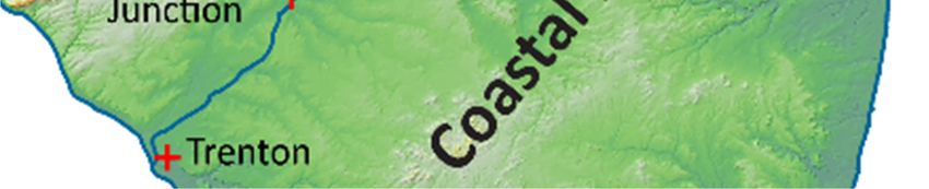
Delmarva Dimensionless
Unit Hydrograph

• Particularly suited for flat, coastal
 areas
 o Watershed slope ≤ 5%
 o Coastal Plain physiography

• Use the same DUH for pre- and post-
 development

 Physiographic
Imagery modified from New Jersey Geological Survey Information Provinces of
Circular, Physiographic Provinces of New Jersey, 2006 38
 New Jersey
Delmarva Dimensionless Unit Hydrograph
https://www.nj.gov/dep/gis/digidownload/metadata/html/Geol_province.html

Physiographic
Provinces of
New Jersey

https://gisdata-njdep.opendata.arcgis.com/datasets/physiographic-
provinces-of-new-jersey

Imagery modified from New Jersey Geological Survey Information
Circular, Physiographic Provinces of New Jersey, 2006 39
Delmarva Dimensionless
Unit Hydrograph
When NOT to use Delmarva Dimensionless
Unit Hydrograph

• Outside of the coastal plain, the Delmarva cannot be
 used.
• In the sizing of an MTD
• The design engineer proves that those conditions are
 present on a site in the coastal plain
 o a completely paved site under the pre-construction condition or
 o average site slope ≥10%

 40
NRCS Rainfall Distributions for Stormwater
Runoff Quantity Control Design Storms
• Typically bell-shaped
• The NRCS rainfall distributions were grouped into four types
 according to the applicable regions or geographic situations.
• TYPE III was previously used for nearly two decades.
• The State was divided into Regions C & D in 2012 and a new
 rainfall distribution replaced the TYPE III distribution in each region
 o Use NOAA_C in Region C: Sussex, Warren, Hunterdon, Somerset,
 Mercer, Burlington, Camden, Gloucester, Atlantic, Salem,
 Cumberland and Cape May Counties.
 o Use NOAA_D in Region D: Bergen, Hudson, Essex, Passaic, Morris,
 Union, Middlesex, Monmouth and Ocean Counties.
 o Note that the C & D distributions will yield higher peak flow rates than
 Type III

 41
NRCS Rainfall Distributions for Stormwater
Runoff Quantity Control Design Storms
NOAA_C and NOAA_D rainfall
distributions, are available online, in
text format, at:
https://www.nrcs.usda.gov/wps/portal/nrcs/
main/nj/technical/engineering/

NOAA_C and NOAA_D rainfall
precipitation distributions and
rainfall intensity will also be
available, in Excel format, from the
Department’s website

 42
Unconnected
Impervious Cover

 43
Unconnected Impervious Cover

How and Why
• We can consider an impervious surface to be unconnected if flow
 can travel as sheet flow onto an adjacent pervious area and meet
 other requirements
• By providing the right conditions to encourage infiltration, some of
 the runoff will provide groundwater recharge, address water
 quality and reduce the volume of runoff requiring treatment by a
 down-gradient BMP

 Impervious Sheet Flow Directed to Sheet Flow Directed to
 Surface Down‐gradient Grass Swale Down‐gradient Stream
 44
Unconnected Impervious Cover
5 Conditions:
An impervious area can be considered to be an unconnected
impervious surface only when meeting all of the following 5
conditions:
a. Upon entering the down-gradient pervious area, all runoff
 must remain as sheet flow

b. Flow from the impervious surface must enter the down-
 gradient pervious area as sheet flow or, in the case of roofs,
 from one or more downspouts, each equipped with a splash
 pad, level spreader or dispersion trench that reduces flow
 velocity and induces sheet flow in the down-gradient
 pervious area

 45
Unconnected Impervious Cover
5 Conditions (cont’d.):
An impervious area can be considered to be an unconnected
impervious surface only when meeting all of the following 5
conditions:
c. All discharges onto the down-gradient pervious surfaces must be
 stable and non-erosive

d. The shape, slope and vegetated cover in the down-gradient
 pervious area must be sufficient to maintain sheet flow
 throughout its length

e. The maximum slope of the down-gradient pervious area is 8%

 46
Unconnected Impervious Cover

Additional Requirements:
Two methods are available for computation of the resultant runoff,
provided the following requirements are met:
a. Only the portions of the impervious surface and the down-
 gradient pervious surface on which sheet flow occurs can be
 considered as an unconnected surface in the calculation. The
 area beyond the maximum sheet flow path length cannot be
 considered in the calculation
b. The maximum sheet flow path length across the unconnected
 impervious surface is 100 ft

c. The minimum sheet flow length across the down-gradient
 pervious surface is 25 ft in order to maintain the required sheet
 flow state of the runoff

 47
Unconnected Impervious Cover
2 Methods Allowed for computation of the resultant runoff :

• The NRCS composite CN with unconnected impervious
 method from Chapter 9, NEH, Part 630
 o This method can be used only when the total impervious
 surface is less than 30 percent of the receiving down-gradient
 pervious surface because absorptive capacity of the pervious
 surface will not be sufficient to affect the overall runoff
 significantly

• The NJDEP Two-Step Method

 48
Example 5-3:
The NJDEP Two-Step Method
Calculate the runoff volume. CN = 98 CN = 39

Assume the soils are HSG ‘A’ and
the depth of rainfall, P = 3.5 in
 200 ft
Step 1: Calculate the Runoff from
 the Impervious Area

S = 10 = 10 = 0.204 25 ft
 Impervious
 75 ft
 Pervious Area
 Grass
 Swale
 Area Sheet Flow
 Sheet Flow
 . . .
 = = 3.27 in
 . . .

Volume = 3.27 200 25 = 1,362.5 cf

 49
Example 5-3:
The NJDEP Two-Step Method
Calculate the runoff volume. CN = 98 CN = 39

Assume the soils are HSG ‘A’ and
the depth of rainfall, P2 = 3.5 in
 200 ft
Step 2: Convert the Runoff from the
 Impervious Surface to a
 Hypothetical Rainfall on the
 Pervious Area 25 ft 75 ft Grass
 Impervious Pervious Area Swale
 , . / Area Sheet Flow
P2 I = = 1.09 in Sheet Flow

P2 I P
 = 3.5 in 1.09 in = 4.59 in
S = 10 = 10 = 15.64
 . . .
 = = 0.125 in
 . . .

Total Effective Volume
 = 0.125 200 75 = 156 cf
 50
NJDEP Two-Step Method

Questions?

You may also submit questions on this topic by email to
DWQ-BNPC-StormwaterManagement@dep.nj.gov

 51
Conditions for using exfiltration
in runoff calculations
 52
Using Exfiltration in
Routing Computations
• See Pages 7 and 8 of Chapter 5
• All soil testing must be fully compliant with Chapter
 12: Soil Testing Criteria
• The design of the BMP must comply with all of the
 design criteria within the respective subchapter of
 Chapter 9
• Pretreatment, in the form of a forebay or any of the
 other BMPs found in the BMP Manual, must be
 incorporated into the BMP design, unless specifically
 stated otherwise
 o For BMPs whose contributory drainage area ≤1 acre, pre-treatment
 is not required

 (cont’d. after next slide)
 53
Pretreatment Requirement

• Roof runoff that directly discharges into the stormwater
 BMP can be pretreated by leaf screens, first flush
 diverters or roof washers. For details of these
 pretreatment measures, see Pages 5 and 6 of
 Chapter 9.1: Cisterns

 54
Pretreatment Requirement (cont’d.)
• This pretreatment requirement for roof runoff can be
 waived by the review agency if the building in
 question has no potential for debris and other
 vegetative material to be present in the roof runoff
• Pretreatment for non-roof runoff, or roof runoff
 comingled with stormwater from other surfaces, must
 be in accordance with the respective BMP Manual
 chapter
 o Pretreatment for subsurface infiltration basins must be consistent
 with Chapter 5 and remove 80% TSS, for which any of the BMPs in
 the BMP Manual may be used
 o For small-scale bioretention systems designed to infiltrate, where
 inflow that is in the form of sheet or overland flow, a 5 foot wide
 gravel or stone filter strip, with a slope of no greater than 10
 percent, can be substituted for the required pretreatment when
 exfiltration is used in the routing calculations
 55
Using Exfiltration in
Routing Computations (cont’d.)

• Exfiltration cannot be used in any BMP designed with
 an underdrain system
• Infiltration of the entire 2-, 10- or 100-year storm is
 allowed only when:
 a. existing site conditions are such that no runoff leaves the site for
 the pre-construction condition scenario, thereby constraining
 the design to infiltrate 100% of the volume produced by the
 post-construction condition for the same design storm. In this
 case, the maximum storm that can be entirely infiltrated is the
 largest storm event with no runoff leaving the site in pre-
 construction conditions, or
 b. the volume of stormwater runoff to be fully infiltrated is required
 by law or rule implemented by the Pinelands Commission,
 Highlands Council, or any other stormwater review agency
 with jurisdiction over the project.
 (cont’d.) 56
Using Exfiltration in
Routing Computations (cont’d.)

• The analysis of groundwater hydrology and the
 hydraulic impact due to the exfiltration, required
 pursuant to N.J.A.C. 7:8-5.2(h), must be conducted in
 conjunction with the design using exfiltration.
 a. The design vertical hydraulic conductivity of the most
 hydraulically restrictive soil horizon below an infiltration type
 BMP may be used as the exfiltration rate in the routing
 calculations only when the soil is tested strictly in accordance
 with Chapter 12
 b. This analysis must be performed using the method outlined in
 Chapter 13: Groundwater Table Hydraulic Impact Assessments
 for Infiltration BMPs

 (cont’d.)

 57
Using Exfiltration in
Routing Computations (cont’d.)
• The runoff volume discarded as exfiltration and the design
 vertical hydraulic conductivity of the most hydraulically
 restrictive soil horizon below an infiltration BMP must be
 used, in the initial model, to calculate the duration of
 infiltration period in the groundwater mounding analysis.
 a. When the groundwater mounding reaches the bottom of the
 BMP, the hydraulic gradient is reduced, thereby reducing the
 exfiltration rate
 b. To reflect the impact on the hydraulic gradient, the reduced
 exfiltration rate must also be used to re-run the routing
 calculation(s) to check the peak flow rate(s) produced for the
 respective design storm(s) through the proposed outlet
 structure of the infiltration BMP used to meet the Stormwater
 Runoff Quantity Standards
 c. If adverse impacts cannot be avoided, the infiltration BMP
 cannot be used.
 58
Using the
Rational Method
 59
Rational Method

Assumptions:
• Rainfall intensity is uniform over the drainage basin
 during the duration of the rainfall

• Maximum runoff rate occurs when the rainfall lasts as
 long or longer than the time of concentration

• The frequency for rainfall and runoff are equal

 60
Rational Method
General Use:
• Used for relatively small drainage areas with uniform
 surface cover (≤20 acres)

• Used for urban areas

• Not applicable if areas of ponding occur

• Used only to estimate the peak runoff rate

 61
Rational Method
Equation:

Q = peak flow(cfs)
c = rational runoff coefficient (dimensionless)
 = average rainfall intensity (in/hr)
A = drainage area basin (acres)

• Rational method runoff coefficient (c ) is a function of the soil
 type and drainage basin slope
• See Table 5-3 for runoff coefficients

 62
Rational Method

Table 5-3:
 , Runoff Coefficients

New Jersey Department of Environmental Protection, Land Use Management Program. 1988.
Technical Manual for Land Use Regulation Program, Bureau of Inland and Coastal Regulations,
NJDEP Flood Hazard Area Permits 63
Rational Method Equation

 = rainfall intensity
NOAA’s National Weather Service
Precipitation Frequency Data Server (PFDS)

 64
Rational Method Equation
 IDF Curve
 = rainfall intensity

 65
NJDEP 1.25-Inch/2-Hour WQDS
Intensity-Duration Curve
 3.2

 Minimum Time of Concentration
 = 10 minutes when using the Rational Method 66
Any Questions?

 Stormwater Management Unit
 Bureau of Flood Hazard and Stormwater Engineering
 Division of Watershed Protection and Restoration

 501 East State Street
 PO Box 420, Mail Code 501-2A
 Trenton, NJ 08625-420
 Tel: 609-633-7021
 www.njstormwater.org

 Anthony Robalik
 Anthony.Robalik@dep.nj.gov

 67
You can also read