STREETLIGHT DESIGN - January 2020 - Technical Design Manual #6 - City of Chandler
←
→
Page content transcription
If your browser does not render page correctly, please read the page content below
STREETLIGHT DESIGN

  Technical Design Manual #6

      January 2020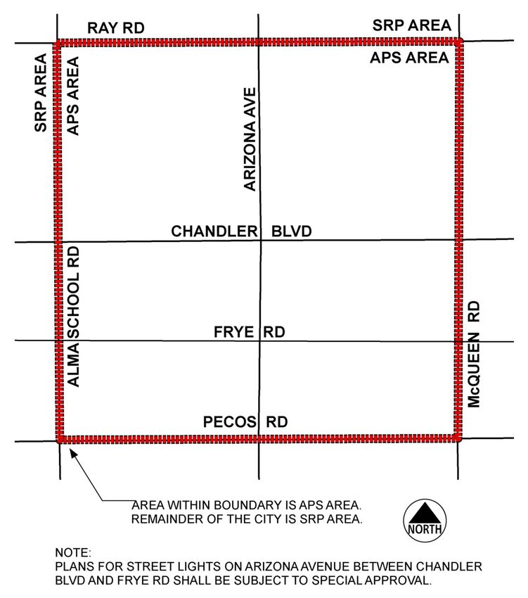
Table of Contents

          POLICY ...................................................................................................................................... 1

          GENERAL .................................................................................................................................. 1

          STREETS IN LOW-DENSITY RESIDENTIAL AREAS ................................................................. 2

1.        SERVICE AREAS ........................................................................................................................ 3

2.        LUMINAIRES ............................................................................................................................. 4

          2.1 GENERAL ............................................................................................................................ 4

          2.2 LED LUMINAIRES............................................................................................................... 4

          2.3 PHOTOCELLS ..................................................................................................................... 5

3.        POLES........................................................................................................................................ 6

          3.1 POLE FABRICATION .......................................................................................................... 7

          3.2 POLE PREPARATION, PAINTING AND IDENTIFICATION .............................................. 8

          3.3 APPROVED MANUFACTURERS ........................................................................................ 9

          3.4 WOOD POLES .................................................................................................................... 9

          3.5 POLE BASES ....................................................................................................................... 9

4.        JUNCTION BOXES ..................................................................................................................10

5.        CONDUCTORS .......................................................................................................................11

6.        TRENCHING AND BACKFILL .................................................................................................11

7.        CONDUITS ..............................................................................................................................13

8.        TRAFFIC CONTROL ................................................................................................................13

9.        STREETLIGHT ENERGIZATION FOR SUBDIVISIONS IN SRP AREA ...................................13

DETAILS (SL-1 – SL-20)................................................................................................................. 15-35

ILLUMINATION STANDARDS (APPENDIX A) ...................................................................................36

City of Chandler                                                                                                          Streetlight Design
January 2020                                                                                                                        TDM #6
CITY OF CHANDLER
PUBLIC WORKS & UTILITIES DEPARTMENT
STREETLIGHT STANDARDS AND SPECIFICATIONS
POLICY:
Developers of residential, commercial, and industrial properties are responsible for
the design and installation of streetlights for the development per the current
subdivision code. Streetlight plans and details shall be included with the
improvement plans and shall be submitted for review by the City Transportation
Engineer. All streetlight designs, materials and installations for public streets shall
conform to the latest edition of the City of Chandler Streetlight Standards and
Specifications. Any deviations from these standards shall be approved by the City
Transportation Engineer. Lighting for private streets shall also meet the shielding
requirements and illumination requirements of these standards. Under no
circumstances shall any streetlight or street lighting system be installed without
approval of the City Transportation Engineer.
GENERAL:
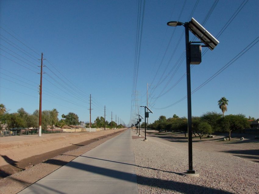
Streetlight designs shall use LED luminaires controlled by individual photocells,
mounted on steel poles. Spacing of luminaires shall be based on illumination level
requirements listed in Appendix A.
New streetlight circuits shall be installed below grade.
Streetlights shall be fully shielded in such a manner that light emitted by the fixture,
either directly from the lamp or indirectly from the luminaires is projected below a
horizontal plane running through the lowest point on the fixture where light is
emitted.
Intersections at all local and collector type streets shall have at least one streetlight
at the intersection. Minor and major arterial intersections shall have at least two
streetlights at the intersection. Near existing or future signalized intersections,
streetlight plans shall be coordinated with streetlights mounted on the traffic
signals. Street surfaces in cul-de-sacs or bubbles must be illuminated to the same
standards as local streets.
City of Chandler 1 Streetlight Design
January 2020 TDM #6
DEVELOPERS SHALL COORDINATE THE LIGHTING SYSTEM DESIGN AND
ELECTRIC SERVICE FOR THE LIGHTING SYSTEM WITH THE UTILITY COMPANY
SERVING THAT SYSTEM.

The Developer shall conform to the latest requirements of the serving utility and
pay all energization fees. Design criteria reproduced here for Salt River Project and
Arizona Public Service are for reference only, and do not relieve the Developer of
any coordination requirements.

Plans for a streetlight system submitted to the City Transportation Engineer for
approval shall show the location of the nearest existing streetlight including details
of luminaire type, output, wattages, mounting height, and pole type. Computerized
point-to-point lighting calculations on all plan submissions are required indicating
maintained foot-candle levels at ten foot intervals between luminaires and across
the width of the roadway for projects. Streetlight plans shall be an individual plan
set except as approved by the City Transportation Engineer.

Contractor shall provide a product cut sheet identifying the specific luminaire
proposed to be used and submit it to the City at the same time as the initial plan
submission. If approved, the City’s engineer responsible for traffic plan review will
forward the cut sheet to SRP, so they can prepare a special billing rate as necessary.

Streetlights for local or collector streets shall generally be located at the side lot
lines on the south or west sides of the streets. On arterial streets, lights shall be
placed on both sides of the street in a staggered arrangement. If medians are
present and are of sufficient width, streetlights may be placed in the median using
poles mounted with double mast arms.

For City streetlight upgrade projects, pole spacing may be varied to meet lot line
requirements and an overhead conductor may be installed when underground
installation is impractical. The City Transportation Engineer must approve all
adjustments.

STREETS IN LOW-DENSITY RESIDENTIAL AREAS:

Low density residential areas with less than 2.5 units per acre may be permitted to
install standard street lights only at intersections in combination with bollard or
similar style of light at individual driveways as described below.

Within the intersection area (defined by extension of roadway tract, roadway
easement, or R/W-boundaries of the intersecting streets), the average illumination

City of Chandler                       2                             Streetlight Design
January 2020                                                                   TDM #6

shall be at least 0.3 foot-candles and the average-to-minimum uniformity ratio shall
be 6 to 1 or less. Lights shall be controlled by photoelectric cells or similar devices
causing them to be turned on automatically during hours of darkness. Any type of
lamp or mounting may be used for intersection lighting, including bollard-style
lights. Lamp fixtures must be designed to minimize glare for motorists, cyclists and
pedestrians. Lamps exceeding 70 watts shall be fully shielded.

Lights shall also be placed on private property at driveway or sidewalk entry from
the private street, and shall illuminate the corresponding address number. These
lights shall be controlled by photoelectric cells or similar devices causing them to be
turned on automatically during hours of darkness. These lights shall be powered
from the individual residences. Homeowner’s associations may choose to specify
the type of lights to be used at driveway entries (e.g., bollard, globe, and gas lamp
style) by codes, covenants and regulations applicable to their subdivision. Lamps
exceeding 70 watts shall be fully shielded.

Very low density residential areas, with lots one acre in size or greater, may be
permitted to omit street lights altogether, with the written approval of the City
Transportation Engineer.

SECTION 1 - SERVICE AREAS

Street lighting in Chandler shall be designed and installed by the developer. Once
installed, ownership shall be turned over to the City of Chandler.

SRP Area:     This area is served by the Salt River Project (SRP) and includes all areas
              of the City except APS Area described below.

APS Area:     This area is served by the Arizona Public Service Company (APS). See
              map below.

City of Chandler                        3                              Streetlight Design
January 2020                                                                     TDM #6
SECTION 2 – LUMINAIRES

2.1      GENERAL

      A. All roadways shall use LED luminaires as specified in Section 3.2 unless
         otherwise approved by the City Transportation Engineer. These luminaires
         shall conform to the Minimum Foot-Candles and Uniformity Ratios as
         specified in Appendix A.

City of Chandler                      4                          Streetlight Design
January 2020                                                               TDM #6
B. All street light relocations shall be replaced with LED luminaires with
         illumination levels to meet City standards per Appendix A.

2.2        LED LUMINAIRES

      A. The entire luminaire shall be warrantied for a minimum of five years.

      B. Housing shall be primarily constructed of corrosion-resistant cast aluminum
         with a powder coated finish to a neutral color.

      C. All mounting hardware shall be of non-corrosive or suitably protected metal.

      D. Luminaire shall mount on a standard 2-3/8” outside diameter arm by means
         of a single piece clamp with an adjustability of +/- 5° to allow for fixture
         leveling.

      E. Weight shall not exceed 28 lbs.

      F. Luminaire shall conform to IESNA TM-15 BUG rating of B2-U0-G2 or better.
         Uplight shall be zero (0) light above 90-degrees.

      G.    (1) The replacement unit for local streets (currently using 100-Watt HPS
                luminaires) shall deliver a minimum of 4,500 initial lumens and operate
                at less than 70 Watts @ 120V through 277V.

            (2) The replacement unit for arterial streets (currently using 250-Watt HPS
                luminaires) shall deliver a minimum of 11,000 initial lumens and
                operate at less than 140 Watts @120V through 277V.

      H. Driver and LED modules shall be replaceable as separate units with tool-less
         plug-in electrical connections.

      I. Cooling shall be done with heat sinks. No fans, pumps, or liquids shall be
         used.

      J. Unit shall be tested and capable of normal operation in ambient
         temperatures of -10° C to +50° Celsius.

City of Chandler                           5                          Streetlight Design
January 2020                                                                    TDM #6
K. Luminaire shall have a minimum 3-lead terminal board mounted within the
      housing. Terminal board screws shall be of the captive type with wire grips
      that raise and lower with the terminal screw. Terminals shall be capable of
      accepting #8 to #14 AWG wire.

   L. Luminaire shall have an LED Correlated Color Temperature (CCT) of 4,000° K.

   M. Color Rendering Index (CRI) shall be a minimum of 70.

   N. L70 (30% lumen loss) shall not occur prior to 90,000 hours at 25° C operating
      temperature. L85 (15% lumen loss) shall not occur prior to 50,000 hours.
      Documentation of independent test results supporting the L70/L85
      projections shall be provided to the City, if requested.

   O. Driver power factor shall be a .90 minimum.

   P. Driver shall have a minimum life rating of 90,000 hours.

   Q. Power supplies shall meet applicable FCC guidelines for interference, with a
      Total Harmonic Distortion of less than 20%.

   R. Luminaires must be independently tested and comply with IESNA LM79-08
      and LM80-08. A copy of all LM79 and LM80 independent test reports shall be
      provided to the City, if requested.

   S. Luminaire housing shall be UL listed for wet locations. Optical assembly shall
      be minimum IP-65 rated per IEC. The unit shall have a minimum vibration
      rating of 2G per ANSI C136.31-2001.

   T. Luminaire shall be provided with a universal voltage driver capable of
      accepting 120V through 277V.

   U. Documentation showing compliance with all performance, mechanical, and
      photometric requirements as detailed above shall be provided to the city, if
      requested.

   V. Approved manufacturers:
        a. GE Evolve
        b. Phillips RoadFocus

City of Chandler                      6                            Streetlight Design
January 2020                                                                 TDM #6
c. Cooper Navion series

      W. Luminaire photocontrol receptacle shall be designed and constructed to
         accept a standard plug type, locking, three-pole, three-wire, streetlight photo
         control. Photocontrol receptacle shall also be configured with the addition
         four conductive pads, as defined in ANSI C136.41.

2.3      PHOTOCELLS

         The photoelectric control shall be twist lock, three-pole type, with a housing
         fabricated of high impact poly-acrylic with an ultraviolet inhibitor. Photo
         control shall be factory set to turn ON at one foot-candle, turn OFF at two
         foot-candles, and installed facing north.

         Photocells shall have a rated life of at least 20 years.

         Electronic photocells shall have surge protection arrestor to protect the
         photocell and luminaires from surges produced by power line switching and
         lighting.

         Photocells used in HPS luminaires shall fail such that the lamp stays ON.
         Photocells used in LED luminaires shall fail such that the lamp stays OFF.

         Approved photocells:

            Long Life:
            Selc #8483
            Ripley #6390
            Fisher Pierce TRS Series

         Approved Photocells for use in HPS Luminaires ONLY:

            Electromechanical:
            Fisher Pierce No. 7760 (120V)
            General Electric No. C402G600 (120V)
            American Electric 8060-4F (120V)
            Fisher Pierce No. 7770 (240V)
            General Electric No. C402G660 (240V)
            Precision Multiple Controls No. 8690 (105-280V)

            Electronic:

City of Chandler                           7                           Streetlight Design
January 2020                                                                     TDM #6
Fisher Pierce No. 7571B (120V)
          Fisher Pierce No. 7572B (240V)
          Precision Multiple Controls No. EC-120 (120-277V)
          Tork No. 5227 (120V)

SECTION 3 - POLES

All new subdivisions and construction projects within the City of Chandler requiring
streetlights shall use the poles as identified by the following pole details:

A.    Detail SL-1 shall be used for all new streetlight installations, except as noted below.

B.    Details SL-6 and SL-8 may be used in the APS service area with approval of the
      Transportation Engineer. SL-6 and SL-8 may not be intermixed with other types of
      poles.

C.    Detail SL-16 may be used as an option to SL-1 throughout a subdivision or major
      non-residential development, with pre-approval of City Transportation Engineer.
      SL-16 may not be intermixed with other types of poles.

D.    Detail SL-17 shall be used in lieu of SL-1 when overhead height restrictions or
      clearance problems exist. SL-17 may not be intermixed with other types of poles.

All poles shall have a minimum setback of 2.5 feet from back of curb, and a one (1) foot
clearance from existing or proposed sidewalk. In certain situations, double davit
streetlights may be placed in the center of the median less than 2.5 feet from back of
curb as approved by the City Transportation Engineer.

       In order to maintain aesthetic continuity along major streets, the same type
       of pole (SL-1 or SL-17) shall be used on both sides of the street for at least
       half-mile sections.

3.1    POLE FABRICATION

       A. Design (Pole SL-1):

          The pole may be either a sectional telescopic design or a tapered design.
          The number, length and diameter of the sections for a sectional telescopic
          design shall be as specified for the varying pole heights. Details SL-1, and

City of Chandler                          8                               Streetlight Design
January 2020                                                                        TDM #6
SL-2 identify the pole and mast arm required for each type of street.
The adjoining sections shall overlap as shown on the standard drawings.
The pole shall provide a rigid support at the mounting height for a fixture
weighing as much as 50 pounds with a projected area of three square
feet. The pole shall be capable of withstanding a wind load of 80 mph per
AASHTO specifications with the fixture attached to a six or eight-foot mast
arm. Steel or aluminum poles are acceptable.
A steel pole shall be constructed of cold rolled mild steel of a sufficient
gauge having yield strength of not less than 36,000 p.s.i..
The pole shall be provided with a hand hole and grounding lug
attachment at the elevation shown on the standard drawings.
The pole shall have a cable entry slot sized and located as shown on the
standard drawings. The slot shall be free of burrs and sharp edges.
B. Design (Poles SL-6 and SL-8):
Poles shall be designed at the top to support 200 lbs. tension pulling
directly under the street light and shall support a 50 lb. luminaires on a 6’-
0” arm 2’-0” above the top of the pole with a 3 sq. ft. area. Pole shall be
capable of withstanding an 80-MPH windload per AASHTO specifications.
Steel or aluminum poles are acceptable.
After fabrication, the pole shall be sandblasted to remove all loose scale,
rust, corrosion products, grease, dirt, and other foreign products.
C. Design (Pole SL-16):
The height and reach of all poles shall correspond to the dimensions of
Detail SL-16.
Poles shall be designed to support the weight of the luminaires and
withstand an 80-MPH windload per AASHTO specifications. The pole
manufacturer shall provide structural calculations and a certificate of
compliance to the specifications.
Pole shafts shall be steel of 48,000 p.s.i. minimum yield after fabrication.
All pipes shall be ASTM A-53 grade “B”, anchor bolts ASTM 1-307, and base
plate and flanges ASTM A-36.
City of Chandler 9 Streetlight Design
January 2020 TDM #6D. Design (Pole SL-17):
The height and reach of all poles shall correspond to the dimensions of
Detail SL-17.
Poles shall be designed to support the weight of the luminaires and
withstand an 80-MPH windload per AASHTO specifications. The pole
manufacturer shall provide structural calculations and a certificate of
compliance to the specifications. Pole shafts shall be steel of 48,000 p.s.i.
minimum yield after fabrication. All pipes shall be ASTM A-53 grade “B”,
anchor bolts ASTM 1-307, and base plate and flanges ASTM A-36.
3.2 POLE PREPARATION, PAINTING AND IDENTIFICATION
A. Poles SL-1, SL-6, SL-8, SL-17:
After sandblasting, the pole shall be galvanized. The galvanizing shall
conform to ASTM A123, latest edition. Zinc (hot galvanized) coating shall
be applied on products fabricated from rolled, pressed and forged steels,
plates, bars and strip.
B. Pole SL-16:
After fabrication, the steel poles shall be sandblasted, primed and powder
coated. Sandblasting shall be in accordance with SSPC Specification SP-6-
63. The color shall be a Dark Bronze equal to Val Spar V40-07.
C. Pole Identification
APS: Contractor to install self-adhesive day and night 1" x 1-1/2" black
on yellow background stickers. Stickers to be mounted
vertically a minimum of 6'-0" from ground. Numbers should be
placed on the side of the pole facing the street. APS will provide
the numbering on the APS electrical drawings.
SRP: Streetlight numbers are placed on the side of the pole facing the
street 6'-0" above finish grade. Surfaces to which numbers are
applied must be clean and free of dirt. Numbers for Joint Use
wood poles installed by SRP to be applied to a plastic I.D. plate,
which are nailed to the pole. These pole numbers typically do
not have alphabetic characters preceding the numbers.
Numbers for steel poles are installed by the Contractor to be
City of Chandler 10 Streetlight Design
January 2020 TDM #6applied directly to the steel pole. The number to be installed is
shown on the job order and will have a “CH” prefix.
D. Existing Poles
Existing Light Gray poles should be repainted to a silver color to match
galvanized poles.
3.3 APPROVED MANUFACTURERS
Poles SL-1, SL-6, SL-8, SL-16 and SL-17
1. CEM-TEC Corporation
2. Ameron
3. Southwest Fabrication
Paint:
A. Pole SL-16; Color: ValSpar V40-07 Dark Bronze or equivalent
1. Sherwin Williams (Polyurethane Enamel)
2. Pittsburgh Paint (Pitthane-Acrylic Urethane Enamel)
3. Val Spar Paint (High Solid -Urethane, 40 series or greater)
B. Pole SL-1 (For maintenance purposes on existing poles)
Color: silver color to match galvanized poles.
Conduit:
1. Carlon
2. Finn Industries, Inc.
3.4 WOOD POLES
Existing wood electrical distribution system poles may be used for mounting
of streetlights, only if approved by the City Transportation Engineer. Use of
these existing wood distribution poles must meet one of the following
criteria:
a. Reduce the pole-forest effect.
b. Where there is no other choice and only in exceptional cases.
Luminaires mounted on existing wood distribution poles shall be furnished
City of Chandler 11 Streetlight Design
January 2020 TDM #6and installed by the utility company owning said distribution line, regardless
of previously delineated service areas. The developer shall coordinate the
design and installation of the luminaires in these areas and shall pay the
"Investment By Others" (IBO) costs to the appropriate utility (APS and SRP
have standard IBO rates). The developer is not permitted to climb on or
attach to these utility company poles. The City shall own the newly installed
luminaires.
3.5 POLE BASES
Concrete bases are required for all streetlights. Concrete for pole
foundations shall be Class A (3000#) and conform to Section 725 of the
Uniform Standard Specifications for Transportation and Development
construction (MAG Specifications).
Reinforcing Steel for concrete foundations shall conform to grade 60
requirements of Section 727 of the Uniform Standard Specifications for
Transportation and Development construction (MAG Specifications).
SECTION 4 - JUNCTION BOXES
4.1 Installation:
A. All junction boxes shall be installed at finish grade.
B. All junction boxes shall be installed adjacent to each pole per detail SL-
14A.
4.2 SRP Service Area Junction Box:
The following is referenced for installation purposes. All J-boxes shall be
placed within 3 feet of streetlight pole and should be located in the public
utility easement where available.
Junction box shall be constructed of Polymer Concrete or High Density
Polyethylene (HDPE) material with a flush mounted bolt-on composite lid.
The box shall be constructed so as to be fire retardant. No wood
components, or other materials, which can be damaged by water or insects,
shall be permitted. The color of the lid shall be gray with the word "STREET
LIGHTING" on it. Dimensions of the box shall be approximately 21" x 15" x
12". The lid shall be set inside the top flange and secured in place with a
minimum of one recessed 3/8" Penta Head bolt. The Penta Head bolt shall
have 0.56" flats per ANSI C57-1226. Box dimensions shown are approximate.
City of Chandler 12 Streetlight Design
January 2020 TDM #6Engineering approval of actual dimensions is required prior to the first
purchase only. This junction box shall be per SRP Specification UVJB4. Refer
to SRP electrical plans to ensure no restrictions or changes have occurred.
Refer to detail SL-14C.
4.3 APS Service Area Junction Box:
The following is referenced for installation purposes. APS will supply all
necessary junction boxes for new streetlights.
10’ x 15” APS Junction Box:
Junction box shall be constructed of a fiberglass or equal material. The outer
coating of the material shall be capable of withstanding abrasion and
sunlight and shall be impact resistant. The entire box shall be capable of
continued water immersion for a prolonged period, with no structural
degradation or visual blemishes. The box shall be constructed so as to be
fire retardant. No wood components, or other material, which can be
damaged by water or insects, etc., shall be permitted. Samples of each new
type of box, or an existing box, which has had a design change, shall be
supplied to the City for testing. The color of the box shall be forest green or
black with a green structural plastic lid. Approximate dimensions shall be
such that a minimum opening of 11-3/4" x 17" will exist when the lid has
been removed. The lid shall be set inside the top flange and marked "STREET
LIGHTING". The lid shall be secured in place with a minimum of one
recessed 3/8" Penta Head bolts. The Penta Head bolt shall have 0.56" flats
per ANSI C57-1226. Box dimensions shown are approximate. Engineering
approval of actual dimensions is required prior to the first purchase only.
Two fuse holders are required by APS, one in pole and one in junction box.
Refer to detail SL-15.
14" x 24" APS Junction Box:
Junction box shall follow the same requirements as 10" x 15" APS junction
box except minimum opening shall be 14" x 24" when lid has been removed.
Refer to detail SL-14B.
SECTION 5 – CONDUCTORS
5.1 Conductors shall be No. 12 AWG solid soft-drawn copper and bear the UL
City of Chandler 13 Streetlight Design
January 2020 TDM #6label except for green grounding. Green ground shall be No. 8 AWG.
Insulation shall be type THWN. The following wire color code shall be used:
Black - 120V power
Black & Red - 240V Power
White - Neutral
Green - Grounding
5.2 Conductors for each luminary shall be connected to the luminaires and
extended down the pole. Terminate conductors in all areas at pullbox
adjacent to pole per Detail SL-15. Connectors shall be made as stipulated in
Section 9.
5.3 It is mandatory that the power conductor for each luminary be fused using
Bussman No. HEB-AA in-line, waterproof fuse holders. Install the fuse
holders inside the pullbox and install Bussman KTK fuses as shown on Detail
SL-15.
SECTION 6 - TRENCHING AND BACKFILL
6.1 SRP SERVICE AREA
A. Refer to Detail SL-18.
B. Trenching:
Conduit located in trenches shall have a minimum cover of 36" below
finished grade and a minimum width of 8". Bottom of trench must be
smooth, flat and without surface irregularities.
C. Backfill:
The first 4" of backfill must be select material consisting of no sharp
rocks, no rocks larger than 3/8" and the ratio of rock to soil is not to
exceed 1 part in 3. When the native backfill does not meet the
requirements, a sand cushion 4" deep shall be installed. Backfill shall
not be performed without approval of SRP.
D. Compaction:
All trenching shall be compacted to a density of 90% of standard
City of Chandler 14 Streetlight Design
January 2020 TDM #6Proctor per MAG Spec. Section 601.4.4, type 1.
6.2 APS SERVICE AREA
A. Refer to Detail SL-19.
B. Trenching:
Trenches shall have a minimum width of 4" and a minimum cover over
conduit of 24". When crossing streets, a 36" minimum cover is
required. However, if conduit is to be installed shallower than 36", the
conduit shall be partially encased with a minimum of 4" concrete
cover, and 2" on the sides, making the minimum trench width 7".
When this encasement rule is applied, the conduit shall have a
minimum cover of 24" from final grade. Bottom of trench must be
smooth, flat, without surface irregularities and free of debris and
organic materials. Developer shall be responsible to assure that trench
and backfill meet current APS requirements.
C. Backfill:
Bedding and shade must be able to pass 100% through a 3/8" sieve,
80% through a #4 sieve, and 60% through a #10 sieve. 6" of level
bedding shall be placed in the trench topped by 8" of shade. Backfill
shall not be performed without approval of APS.
D. Compaction:
At least 6" of select material must be placed over the facility before
tamping. Acceptable compaction methods are hand tamping with
pneumatic or vibrating equipment, and water jetting or flooding in
accord with MAG Specs. Section 601.4.5 Compact backfill to a density
of 90% of standard Proctor MAG Spec Section 601.4.4, type 1.
Note: Trenching requirements are reproduced here for reference only.
Developer shall coordinate trenching requirements with the appropriate
utility company.
City of Chandler 15 Streetlight Design
January 2020 TDM #6SECTION 7 – CONDUITS
Conduits shall be installed between poles and junction boxes in all areas as shown
on Details SL-15. Conduit required for street, alley or driveway crossings should be
2-1/2", schedule 40 polyvinyl chloride for all installations.
Conduit runs between streetlight pole and junction box shall be 1-inch. The conduit
shall be either 1-inch schedule 40 polyvinyl chloride or liquidtight flexible
nonmetallic conduit that confirms to the installation and use specifications set forth
in the 1997 National Electric Code, section 351. The flexible conduit shall not be
used under the following conditions:
1. Where subject to physical damage;
2. Where any combination of ambient and conductor temperatures is in
excess of that for which the liquidtight flexible nonmetallic conduit is
approved;
3. In lengths longer than 6 feet;
4. Where voltage of conductors is in excess of 600 volts, nominal.
Refer to section 356 of the 2011 National Electric Code for additional criteria on
installation and materials for liquidtight flexible nonmetallic conduit.
SECTION 8 - TRAFFIC CONTROL
The Contractor or the utility company is responsible for providing work zone traffic
control in accordance with City of Chandler Traffic Barricade Manual.
SECTION 9 - STREETLIGHT ENERGIZATION FOR SUBDIVISIONS IN SRP AREA
The purpose of this procedure is to ensure timely energization of streetlights within
subdivisions in the SRP service area.
The streetlight energization procedure is separated into three primary areas of
responsibility: that of the City of Chandler, the Developer/electrical Contractor, and
the Salt River Project.
CITY OF CHANDLER:
1. The City will review and approve the proposed streetlight plans.
City of Chandler 16 Streetlight Design
January 2020 TDM #62. The City will return the approved plans (two sets) along with a letter of
authorization and a streetlight energization request to the Developer.
3. The City authorizes SRP to begin streetlight energy billing after
completion of the job order.
DEVELOPER/CONTRACTOR:
1. The Developer shall coordinate all project activities with the utilities in
the area including submittal of approved streetlight plans, civil plans,
authorization letter to bill the City, and the energization request form
previously submitted to the Developer.
2. The Contractor will install all the streetlights as shown in the approved
job plan.
3. The Contractor will install junction boxes in accordance with Section 4
and Detail SL-14A.
4. The Contractor shall affix a streetlight number on each pole as shown
on the job order plan prior to final inspection according to Detail SL-3.
5. Within new subdivisions in the SRP area, the Contractor will connect and
energize each streetlight in the junction box utilizing the connectors in
place as shown on Detail SL-15. In all other cases, the connection will be
made by servicing utility company.
6. Contractor shall limit street light outage to no more than three calendar
days.
SALT RIVER PROJECT:
1. SRP will initiate design of a job order plan to serve a new development
when a letter of authorization, approved civil plans and approved
streetlight layout have been received.
2. SRP will inspect and coordinate the trenching detail and underground
conduit requirement for the primary and secondary conductors.
3. SRP will schedule construction crews to install transformers, pull wire,
terminate and energize all conductor cables following receipt of the
corresponding recorded subdivision plat.
City of Chandler 17 Streetlight Design
January 2020 TDM #64. SRP will add installed and/or planned streetlight units for the
subdivision to the City of Chandler monthly lighting service bill after
completion of the job order work at the site.
City of Chandler 18 Streetlight Design
January 2020 TDM #6SINGLE DAVIT ARM DOUBLE DAVIT ARM
DETAIL REF. TYP.
SL-2, TYPE A
t
D
C
---@ e--
l
C
E
@--
B
B
JUNCTION BOX
SEE DETAIL
SL-14A
8' GROUND ROD
SEE DETAIL SL-14A
STREET TYPE POLE A B C D E
LOCAL SINGLE 11.5' a·-o· 6'-0" 4'-6" 30•-o·
LOCAL WITH MEDIAN DOUBLE 11.5' 8'-0" 6'-0" 4'-6" 30'-o"
MINOR COLLECTOR W/O MEDIAN SINGLE 13.5' 9'-6" 5'-6" 7'-0" 35'-6"
MINOR COLLECTOR W/ MEDIAN DOUBLE 13.5' 9'-6" 5'-6" 7'-0" 35'-6"
ARTERIAL/MAJOR COLLECTOR 9'-6" 7'-0"
SINGLE 13.5' 5'-6" 35'-6"
WITHOUT MEDIAN
ARTERIAL/MAJOR COLLECTOR 9'-6" 7'-0"
DOUBLE 13.5' 5'-6" 35'-6"
WITH MEDIAN
NOTES:
1. POLE SHALL BE MINIMUM 1' -0" BEHIND SIDEWALK UNLESS OTHERWISE DIRECTED. IN NO
CASE WILL THE FACE OF POLE BE LOCATED LESS THAN 2' -6" BEHIND THE BACK OF CURB.
2. POLE SHALL BE MIDWAY BETWEEN CURBS OF THE MEDIAN.
3. DIMENSION 'A' MAY NEED TO BE INCREASED IF GRADE DROPS BELOW CURB LINE.
4. A 2 SECTION TELESCOPIC POLE OF SIMILAR STRENGTH AND HEIGHT WILL ALSO BE ACCEPTED.
5. IF IN SIDEWALK, THEN POUR FLUSH.
Revised May 2018
DETAIL NO.
POLE ASSEMBLY
SL-1
NTS
City of Chandler 19 Streetlight Design
January 2020 TDM#6DETAIL SL-1
IS INTENTIONALLY LEFT BLANK.
....
Revised May 2018
City of Chandler DETAIL NO.
Q POLE ASSEMBLY
SL-1A
Chandler + Arizona �'(]: [P@@U: 0::::, Ei ® [}o'(J: �U:® IT[} @J ® [P@ NTS
City of Chandler 20 Streetlight Design
January 2020 TDM#66"1-----
MAST ARM 1-1/4"
SCHEDULE 40 PIPE
1/4" X 4-1/2" DIA.
STEEL PLATE
SEE NOTE 1 BELOW
3-1/2" SCHEDULE 40 PIPE
MIN. WALL THICKNESS .226"
DOUBLE DAVIT ARM
I STREET TYPE I RADIUS A I PLATE DIA. BI O.D. PIPE C I DAVIT ARM TO BE 2"
SCHEDULE 40 PIPE MIN.
LOCAL 4• - o" WALL THICKNESS .154"
MINOR
COLLECTOR
4• - o" 4 - 1/2" 4"
ARTERIAL/MAJOR
6' - 6"
COLLECTOR
6"
SEE NOTE 1 2"(BOTTOM OF
DAVIT ARM)
DAVIT ARM (C) SCHEDULE 40 PIPE
MIN. WALL THICKNESS .237"
@
NOTE:
1. THREE HOLES, DRILLED AND TAPPED TO ACCOMODATE 1/2" ALLEN SET
°
SCREWS, SPACED 120 APART HORIZONTALLY AND 1-1/2" BELOW
STEEL PLATE. (SEE DETAIL SL-3D)
2. FINISH TO MATCH THAT SPECIFIED FOR THE POLE.
City of Chandler DETAIL NO.
DAVIT ARMS
(POLE SL-1) SL-2
@'O: IT'®®'O: °= Ei ® [}o 'O: @'O:@ [n)@@ [?@ NTS
City of Chandler 21 Streetlight Design
January 2020 TDM#6DETAIL SL-2A
IS INTENTIONALLY LEFT BLANK.
Revised Jan 2020
.....
City of Chandler DETAIL NO.
0.
11 11
BLANK
SL-2A
Chandler + Arizona �U:[?@@'O: 11:::, El® D=o'O: �'O:@ IJD@@ C?@J NTS
City of Chandler 22 Streetlight Design
January 2020 TDM#61,,
1,,
1,,
1,,
1,,
1,, WELD IS-- .....
1,, CONTINUOUS
1,, AND GROUND
1,, SMOOTH.
1,,
1,,
POLE JOINTS
NOTE: REFER TO SECTION 4.2 FOR
POLE IDENTIFICATION.
POLE NUMBER LOCATIONS
THREE 1/2" ALLEN HEAD SET SCREWS SPACED
120 ° APART HORIZONTALLY AND 1-1/2"
BELOW STEEL PLATE
SEE NOTE 1
ON SL-2
1/ 4" HOLE, DRILLED 11/16"
AND TAPPED 20 T THRU
HOLE
DAVIT ARM CONNECTION
DETAIL NO.
DETAILS
(POLE SL-1) SL-3
� 'iJ: IT'® @'iJ: °=El@ Gu 'iJ: � 'iJ:@ ITu @J@ IT'@ NTS
City of Chandler 23 Streetlight Design
January 2020 TDM#6SEE NOTE� SEE SL-5 FOR DAVIT ARM TYPE
�6� �� p�fi
L
AND FOUNDATION
7
\\
JUNCTION BOX, SEE DETAIL SL-14A
SEE NOTE 1
F.G.
CURB
8' GROUND ROD
SEE DETAIL SL-14A I 24"•
STREET TYPE POLE MAST ARM
LOCAL SL-6 SL-5 DTL. 1
MINOR COLLECTOR SL-6 SL-5 DTL. 2
LOCAL WITH MEDIAN SL-8 SL-5 DTL. 1
MINOR COLLECTOR WITH MEDIAN SL-8 SL-5 DTL. 2
ARTERIAL/MAJOR COLLECTOR WITH MEDIAN SL-8 SL-5 DTL. 3
ARTERIAL/MAJOR COLLECTOR WITHOUT MEDIAN SL-8 SL-5 DTL. 3
NOTES:
1. POLE SHALL BE MINIMUM 1' - 0" BEHIND SIDEWALK UNLESS OTHERWISE
DIRECTED. IN NO CASE SHALL THE FACE OF POLE BE LOCATED
LESS THAN 2' -6" BEHIND THE BACK OF CURB.
2. POLE SHALL BE MIDWAY BETWEEN CURBS OF THE MEDIAN WHEN
USING DOUBLE DAVIT ARMS.
3. IF IN SIDEWALK, THEN POUR FLUSH.
Revised May 2018
City of Chandler DETAIL NO.
POLE ASSEMBLY
(POLES SL-6 AND SL-8) SL-4
�'(]: [P@@'O: [1= Ei ® [}i)'(J: �'O:® Di) @J ® [P@ NTS
City of Chandler 24 Streetlight Design
January 2020 TDM#68' o" 6"
6' o" 6"
3'
1' 8"
2 3/8" O.D. STANDARD
SCHEDULE 40 PIPE 2 3/8" O.D. STANDARD SCH. 40 PIPE
ARTERIAL STREETS COLLECTOR & LOCAL STREETS
SHALL ACCEPT WELD TO /4"
A STANDARD POLE
2" NOMINAL
(2 3/8" O.D.) 1/2"
4 1/2" 1 3/4"
DIA.
\ 1/2"
2ND SIMPLEX 1/2" X 5/8"
@ 180" DRILL AND TAP
FITTING FOOT HEX HEAD CAP
SCREW
FOR 1/2" CAP
SCREW
FITTING SHOE
Revised May 2018
City of Chandler DETAIL NO.
DAVIT ARM
(POLES SL·& AND SL-8) SL-5
®'Cl: C?@®'O: °=El@ Gu'O: ®'Cl:® 1Ju @J ® IT'@ NTS
City of Chandler 25 Streetlight Design
January 2020 TDM#61/2"
EVEL EDGES
1/2" OF HAND HOLE
BEND COVER TO
t.
SUGHTL Y SMALLER
RADIUS THAN POLE
s·-o· <
i5
HAND HOLE
X
s�1tJt DIA•
iq
�uV�/gAP
.,........,,,......... THROUGH
POLE
3•
g•
1-1/ " DIA. HOLE GROUNDING
1 so· FROM ARM
4
< ATTACHMENT
s·-o· i5 (WIRE ENTRY)
POLE TOP
X
iq
25•-o·
t NOTES:
1. THE HAND HOLE TO BE 4"X3" WITH 1-1/2"
RADII. THE HAND HOLE COVER TO BE
4"X6"X16 GAUGE WITH 2" RADII AND BEND TO
SLIGHTLY SMALLER RADIUS THAN THE POLE.
i------t3 THE COVER IS TO BE SECURED WITH 2 ( ) 1/4"
STAINLESS STEEL TAMPER PROOF SCREWS,
SUPPLIED BY THE MANUFACTURER.
2. AFTER FABRICATION, THE POLE SHALL BE
SANBLASTED TO REMOVE ALL LOOSE SCALE,
RUST, CORROSION PRODUCTS, GREASE, DIRT,
2·csEE NOTE 6) AND OTHER FOREIGN PRODUCTS.
F.G. riim �*...,.=l'
"ff
iiin'-,,.
'----"-,-,.
_I 3. AFTER SANDBLASTING, THE POLE SHALL BE
_____,.......,,.,..,...,.,-,---1 :::;:=tt'.jj:!':=t 1-,,--.,....,.....,.--.-- GALVANIZED. THE GALVANIZING SHALL CONFORM
·:·n:· · =-J:• ;;y
� � //.
W 1TH ASTM A123, LATEST EDITION. ZINC
4 _ 1.x36.x4• BOLTS -,i:;.-t:%- J:1 .
✓, ·,, "'
HOT GALVANIZED) COATING ON PRODUCTS
w/2 NUTS AND 2 WASHERS . (
WIRE ENTRY·----·' •. ,. .
---t-c.ol;....._."-+' FABRICATED FROM ROLLED, PRESSED AND
.. b
4 - f/7 (GR. 60) W/(13 ·
. . .. ► ·. I
FORGED STEELS, PLATES, BARS AND STRIP.
·· -. :• . • ·
TIES AT s· (2 AT 3• TOP) . •. . co 4. POLE SHALL BE DESIGNED AT THE TOP TO
. ..... ·-�·.
SUPPORT 200 LBS. TENSION PULLING DIRECTLY
110>�:J.: ·1
UNDISTURBED EARTH
UNDER THE STREET LIGHT AND SHALL SUPPORT
A 50 LB LUMINARE ON A 6' -0" ARM 2' -0"
ABOVE THE TOP OF THE POLE WITH A 3 SQ. FT.
I• I 2
4
•- •
AREA.
WIND.
POLE SHALL ALSO WITHSTAND AN 80 MPH
5. SEE DETAIL SL-17 FOR BASE PLATE & FOUNDATION.
6. IF IN SIDEWALK, THEN POUR FLUSH.
REFER TO SL-7 FOR
PART NUMBER DESCRIPTIONS G) THROUGH @
-·
Revised May 2018
City of Chandler DETAIL NO.
0.. POLE DETAILS
SL-6
CHANDL�ARIZONA @'iJ:[?@@'iJ: D::::,El� o=ou: @u:@o=o@@[?@ NTS
City of Chandler 26 Streetlight Design
January 2020 TDM#6ITEM QUANTITY DESCRIPTION
1 PIPE, 3-1/2" O.D. 0.109" WALL 8'-6" LONG
2 PIPE, 4-1/2" 0.D. 0.125" WALL 8'-6" LONG
3 PIPE, 5-9/16" 0.D. 0.188" WALL 14'-0" LONG
4 CAP, 3-1/2" I.D. STANDARD SLIP ON
5 SIMPLEX, UNIVERSAL CT-2 PER EM-912
6 PIPE, 1-1/2" MIN. I.D. STEEL 3-1/2" LONG
7 2 LUG, TERMINAL (BLACKBURN L70 OR EQUIVALENT)
8 BOLT, 1/4" X 3/4" ROUND HEAD - RIBBED SHANKED WITH NUT
9 WASHER, 1/4" ROUND
10 2 SCREW, 1/4" STAINLESS STEED TAMPER PROOF
11 1 PLATE, COVER, 16 GA. STEEL
12 PLATE, BUTT 4" X 4" X 3/16"
13 WASHER, SINGLE COIL LOCK
City of Chandler DETAIL NO.
POLE DETAILS
(POLE SL·&) SL-7
� 'O: IT'®®U: 11:::, Ei � [}=o 'O: � 'O: GU ITu @J GU IT'@J
City of Chandler 27 Streetlight Design
January 2020 TDM#6<
9'-0" 0
X
"!
1-1/4" DIA. HOLE
180 "FROM ARM
ATTACHMENT
GROUNDING (WIRE ENTRY)
POLE TOP
<
0
9'-6"
X
"!
32'-0"
EVEL EDGES
1/2" OF HAND HOLE
BEND COVER TO
SUGHTLY SMALLER
13'-5"
HAND HOLE RADIUS THAN POLE
NOTES:
1. THE HAND HOLE TO BE 4"X3" WITH 1-1/2" RADII. THE
HAND HOLE COVER TO BE 4"X6"X16 GAUGE WITH 2"
RADII AND BEND TO SLIGHTLY SMALLER RADIUS THAN THE
NOTE 6) POLE. THE COVER IS TO BE SECURED WITH (2) 1/4"
STAINLESS STEEL TAMPER PROOF SCREWS, SUPPLIED BY
F.G. THE MANUFACTURER.
2. AFTER FABRICATION, THE POLE SHALL BE SANDBLASTED TO
4 - 1 "X36"X4" BOLTS ---F-+;,_it,._"1-F-'1---H'L-__,_, REMOVE ALL LOOSE SCALE, RUST, CORROSION PRODUCTS,
W/2 NUTS AND 2 WASHERS· ... · GREASE, DIRT, AND OTHER FOREIGN PRODUCTS.
.---t- illoiii...,._-t-'
WIRE ENTRY ----- _ _ _
:-,1
3. AFTER SANDBLASTING, THE POLE SHALL BE GALVANIZED. THE
4 - #7 (GR. 60) W/#3 GALVANIZING SHALL CONFORM WITH ASTM A123, LATEST
TIES AT 8" (2 AT 3" TOP) EDITION. ZINC (HOT GALVANIZED) COATING ON PRODUCTS
��.,==.=,,.............
FABRICATED FROM ROLLED, PRESSED AND FORGED STEELS,
UNDISTURBED EARTH PLATES, BARS AND STRIP.
4. POLE SHALL BE DESIGNED AT THE TOP TO SUPPORT 200
I• 24"
� - I LBS. TENSION PULLING DIRECTLY UNDER THE STREET LIGHT
AND SHALL SUPPORT A 50 LB LUMINAIRE ON A 6'-0" ARM
2'-0" ABOVE THE TOP OF THE POLE WITH A 3 SQ. FT.
AREA. POLE SHALL ALSO WITHSTAND AN 80 MPH WIND.
5. SEE DETAIL SL-17 FOR BASE PLATE AND FOUNDATION.
6. IF IN SIDEWALK, THEN POUR FLUSH.
REFER TO SL-9 FOR PART NUMBER DESCRIPTIONS
G)THROUGH@ Revised May 2018
City of Chandler DETAIL NO.
POLE DETAILS
SL-8
NTS
City of Chandler 28 Streetlight Design
January 2020 TDM#6ITEM QUANTITY DESCRIPTION
PIPE, 4-1/2" O.D. 0.125" WALL 9'-6" LONG
2 PIPE, 5-9/16" O.D. 0.134" WALL 10'-0" LONG
3 PIPE, 6-5/8" O.D. 0.188" WALL 20'-0" LONG
4 CAP, 4-1/2" I.D. STANDARD SLIP ON
5 PLATE, COVER, 16 GA. STEEL
6 SCREW, 1/4" STAINLESS STEEL TAMPER PROOF
7 2 PIPE, 1-1/2" MIN. I.D. STEEL 3-1/2"
8 SIMPLEX, UNIVERSAL CT-2 PER EM-912
9 LUG, TERMINAL (BLACKBURN L70 OR EQUIVALENT)
10 2 BOLT, 1/4" X 3/4" ROUND HEAD-RIBBED SHANKED WITH NUT
11 WASHER, 1/4" ROUND
12 PLATE, BUTT 4-5/8" X 4-5/8" X 3/16"
13 WASHER, SINGLE COIL LOCK
City of Chandler DETAIL NO.
POLE DETAILS
(POLE SL-8) SL-9
@'O: IY®®'O: °=El® Gu 'O: @'O: cID ITO @J cID [?@
City of Chandler 29 Streetlight Design
January 2020 TDM#6DETAILS SL-10, SL-11, SL-12, AND SL-13
ARE INTENTIONALLY LEFT BLANK.
0....
City of Chandler DETAIL NO.
11
BLANK11
Chandler + Arizona �U:CP®®U: 0::::, El® [}ou: �u:@ ITu @J@ CP@ NTS
City of Chandler 30 Streetlight Design
January 2020 TDM#6+
GROUND ROD
5/8"x8'O"
(AREA A & C)
1" CONDUIT WITH
_______,___
JUNCTION BOX MAY STREETLIGHT
I
CD
0::: MAY BE LOCATED CONDUCTORS
:::, ON EITHER
(.)
SIDE OF POLE.
3' MAX I
1\ GROUND ROD
5/8"x 8' MIN.
(AREA S)
2' MAX WHEN NO SRP COPPERCLAD
P.U.E. AVAILABLE STEEL
2' MAX WHEN NO
-----------,-APS
P.U.E. AVAILABLE
COVER TO BE FLUSH
WITH FINISH GRADE PREFERRED POLE LOCATION IS ON THE
SOUTH AND WEST SIDES OF THE STREET
.. ,
_
RIGHT
-OF
I
VARIES
WAY P.U.E. AREA
BACKFILL WITH EXCAVATED
GROUND ROD (AREA S) MATERIAL. COMPACTION
5/8" X 8' O" MIN. BENEATH AND AROUND JUNCTION
BOX SHALL BE A MINIMUM OF 85%
SEE SECTION 5 FOR COVER SPECIFICATIONS
DETAIL NO.
JUNCTION BOXES
SL-14A
NTS
City of Chandler 31 Streetlight Design
January 2020 TDM#6DIMENSIONS SHOWN ARE APPROXIMATE. ACTUAL DIMENSIONS
TO BE APPROVED BY THE CITY TRANSPORTATION ENGINEER.
-·
City of Chandler DETAIL NO.
1 4 11 X 2411 JUNCTION BOX
APS SERVICE AREA SL-14B
Chandler + Arizona �'(]: [r'@@'O: °= El @ Gu'(]: �'(]: ® ITO @J ® [r'@ NTS
City of Chandler 32 Streetlight Design
January 2020 TDM#6DIMENSIONS SHOWN ARE APPROXIMATE. ACTUAL DIMENSIONS
TO BE APPROVED BY THE CITY TRANSPORTATION ENGINEER.
1 011 X 1511 JUNCTION BOX DETAIL NO.
APS AND SAP SERVICE AREA SL-14C
�'O: Cf'@@'O: °=El@ DD'O: �'O: @ITD @J@ Cf'@ NTS
City of Chandler 33 Streetlight Design
January 2020 TDM#6TO LUMINAIRE
TO 2ND LUMINAIRE
(MEDIAN POLES ONLY)
'+---WHITE (120V)
RED (240V)
JUNCTION BOX
2"(SEE NOTE 3) FUSE HOLDER
F.G. ,....._��11111H=t,illlllll'-'
hi
...,_,
_l__ GROUND WIRE
8' GROUNDING ROD
WITH CLAMP, SEE
DETAIL SL-14A
BY SRP
UNDISTURBED EARTH 1" CONDUIT
� SEE SECTION
SRP AREA I. 24•0 • I 14 FOR CRITERIA
TO LUMINAIRE
'+---WHITE (120V)
RED (240V)
FUSE HOLDER
1.i-1-----=::::--GREEN
JUNCTION BOX
FUSE HOLDER
F.G.
CONDUCTORS
BY APS
CONNECTORS
BY APS
UNDISTURBED EARTH �
[Jj:./41 ---- 1" CONDUIT
SEE SECTION
14 FOR CRITERIA
1 • 24"¢ • �
8' GROUND ROD
SEE DETAIL SL-14A
APSAREA
NOTES:
1. FOR CITY OR DEVELOPER INSTALLED AND CITY MAINTAINED FUSING IN APS AREAS,
APS TO PROVIDE AND INSTALL 15AMP FUSES IN JUNCTION BOX. CUSTOMER
FUSING IN THE HANDHOLE NOT TO EXCEED 10 AMPS. FOR APS REQUIREMENTS
CONTACT APS ENGINEERING.
2. FOR CITY OR DEVELOPER INSTALLED AND CITY MAINTAINED FUSING IN SRP AREAS
CONTACT SRP ENGINEERING FOR REQUIREMENTS.
3. IF IN SIDEWALK, THEN POUR FLUSH. Revised May 2018
City of Chandler DETAIL NO.
CONNECTION DETAILS
SL-15
NTS
City of Chandler 34 Streetlight Design
January 2020 TDM#6DOUBLE DAVIT ARM IN MEDIAN SINGLE DAVIT ARM
PEC
2 3/8" O.D.
TENON X 6"
2 3/8" O.D.
TENON X 6"
5" SQUARE POLE. 4" SQUARE POLE.
PAINT DARK BRONZE PAINT DARK BRONZE
TO MATCH FIXTURE. TO MATCH FIXTURE.
HEIGHT .188 MINIMUM WALL HEIGHT .188 MINIMUM WALL
THICKNESS (7 GA.). THICKNESS (7 GA.).
2" SEE NOTE 5 CENTER POLE
BETWEEN CURBS 1'-0"
-CURB
F.G.
4 - 1 "X36"X4" BOLTS ·
W/2 NUTS AND 2 WASHERS· ...· /, .:·.
WIRE ENTRY ····- , .•. , ·
4 - #7 (GR. 60) W/#3 .: , · , .·· •• ·. I10"X10" SQ. X 1" THICK BASE
15• - o" PLATE WITH 4 - 1 1/4" 0
✓----:--..
HOLES ON A 10 1/2"
BOLT CIRCLE
2 3/8" O.D. STD. PLAN VIEW
PIPE TENON x 6" 3" X 5" OVAL HAND
I
I HOLE WITH COVER
°
(!) LOCATED 90 FROM
[iJ 7/8" O.D.
I MAST ARM
STD. WALL
(!)
z F.G.
�
z
::::>
0 TELESCOPIC JOINT--
''-•," ,, . ..
,,(:(/A,/,SRP REQUIREMENTS
STANDARD STREETLIGHT CONDUIT ENCASEMENT UNDER
EXCAVATION PAVED SURFACE ONLY
REPLACE ASPHALT
SURFACE. T -TOP WHEN
FINISH GRADE LATERAL lYPE A
DTL. 200 WHEN LONGITUDINA
COMPACTED A.B.C.
36" 36"*
4" SELECT BACKFILL
OR SAND CUSHION
12" CONCRETE SLURRY SHALL
BE PLACED IN 2 - 6" LIFTS.
SRP SHALL INSPECT & APPROVE
1ST LIFT AND CONDUIT, PRIOR
TO PLACEMENT OF SECOND LIFT.
8'-' ______,_,.
-----8"
NOTES:
1. EACH CONDUIT SHALL TERMINATE IN EACH JUNCTION BOX AND/OR POLE FOUNDATION.
2. IF lYPE AND SIZE OF CONDUIT ARE NOT SPECIFIED, THE DEVELOPER SHALL SUBMIT
PLANS SHOWING SIZE OF EACH CONDUIT, ITS LOCATION AND THE NUMBER AND lYPE
OF WIRES CONTAINED IN EACH, TO THE CllY ENGINEER FOR APPROVAL.
3. THE BOTTOM OF THE TRENCH SHALL BE SMOOTH AND FREE OF OBSTRUCTIONS. SAND
OR CLEAN, TAMPED BACKFILL MATERIAL SHALL BE PLACED ON THE BOTTOM IF SHARP
ROCKS ARE PRESENT, TO PREVENT DAMAGE TO THE PVC.
* 4. 48" MINIMUM COVER WHEN USED IN PUBLIC UTILllY EASEMENTS (PUE).
City of Chandler DETAIL NO.
CONDUIT EXCAVATION CRITERIA
SL-18
NTS
City of Chandler 37 Streetlight Design
January 2020 TDM#6APS REQUIREMENTS
STANDARD STREETLIGHT
EXCAVATION
FINISH GRADE
*24"
♦
6" SELECT BACKFILL
*4" -----
NOTES:
1. EACH CONDUIT SHALL TERMINATE IN EACH JUNCTION BOX, OR WHEN SPECIFIED, IN A POLE.
2. IF lYPE AND SIZE OF CONDUIT ARE NOT SPECIFIED, THE DEVELOPER SHALL SUBMIT PLANS
SHOWING SIZE OF EACH CONDUIT, ITS LOCATION AND THE NUMBER AND lYPE OF WIRES
CONTAINED IN EACH, TO THE CllY ENGINEER AND APS FOR APPROVAL.
3. THE BOTTOM OF THE TRENCH SHALL BE SMOOTH AND FREE OF OBSTRUCTIONS. SAND OR
CLEAN, TAMPED BACKFILL MATERIAL SHALL BE PLACED ON THE BOTTOM IF SHARP ROCKS
ARE PRESENT, TO PREVENT DAMAGE TO THE PVC.
*4. 36" MINIMUM COVER REQUIRED WHEN CROSSING STREETS. HOWEVER, IF CONDUIT IS TO BE
INSTALLED SHALLOWER THAN 36 INCHES, THE CONDUIT SHALL BE PARTIALLY ENCASED WITH
A MINIMUM 4" CONCRETE COVER ON TOP, AND 2" ON THE SIDES, MAKING THE MINIMUM
TRENCH WIDTH 7". WHEN THIS ENCASEMENT RULE IS APPLIED, THE CONDUIT SHALL HAVE
A MINIMUM COVER OF 24" FROM FINAL GRADE.
DETAIL NO.
CONDUIT EXCAVATION
CRITERIA SL-19
� U: Cr'®®U: 11:::, Ei@ Gu U: � U:@ ITO@J cID Cr'@ NTS
City of Chandler 38 Streetlight Design
January 2020 TDM#6A t>
1-1/4"0 ANCHOR BOLTS
A -ff----------jf----+-J---b------,:=---¥"
-t> .
A
t> '.·>
'
..
.. --�•.· :
A
5 EACH #4 STIRRUPS
PLACED AS SHOWN
3"
PLAN #5 AT 14" O.C. EACH WAY
TOP AND BOTTOM
;,""-/"o/
1//,
v""-"-Illumination Standards
Uniformity
Street Type and Average
Ratio Pole Spacing Mounting
Road Width Land Use Foot-
(Ave-to- Type Pattern Height
(B.C. to B.C.) Candles
Min)
Commercial 1.3
Arterial SL-1 or
Intermediate 1.1 3:1 Staggered 35'
'76 to 100' SL17
Residential 0.8
Industrial SL-1 or
Intermediate 0.7 4:1 Staggered 35'
Collector 65' SL16
Commercial 0.9
Residential SL-1 or Single
Intermediate 0.7 4:1 35'
Collector 45' SL16 Sided
Residential 0.5
Commercial 0.7
Local SL-1 or Single
Intermediate 0.5 6:1 30'
35' SL16 Sided
Residential 0.3
Commercial - Downtown areas, regional shopping centers, major sport complexes and
other areas with a high level of nighttime vehicular and pedestrian activity.
Intermediate - Libraries, community centers, colleges, neighborhood shopping centers, and
other areas with a moderate level of nighttime vehicular and pedestrian activity.
Residential - Residential developments, and
other areas with a low level of nighttime vehicular and pedestrian activity.
City of Chandler City Transportation Engineer to determine classification to be used in design.
These standards apply to all illumination technologies, including LED, HPS, MH and Induction.
Light levels shall not exceed 10% of the Average Foot-Candles shown above.
....
Revised May 2018
City of Chandler
STANDARD STREETLIGHTING APPENDIX
INSTALLATIONS / ILLUMINATION
STANDARDS A
Chandler + Arizona � 'O: II'@@'O: °=El® Gu 'O: � 'O: ® Di)@ ® II'@
City of Chandler 40 Streetlight Design
January 2020 TDM#6You can also read