PURE STORAGE FOUNDATION STUDY GUIDE - EXAM NUMBER: PCA_001
←
→
Page content transcription
If your browser does not render page correctly, please read the page content below
PURE STORAGE FOUNDATION
STUDY GUIDE
EXAM NUMBER: PCA_001
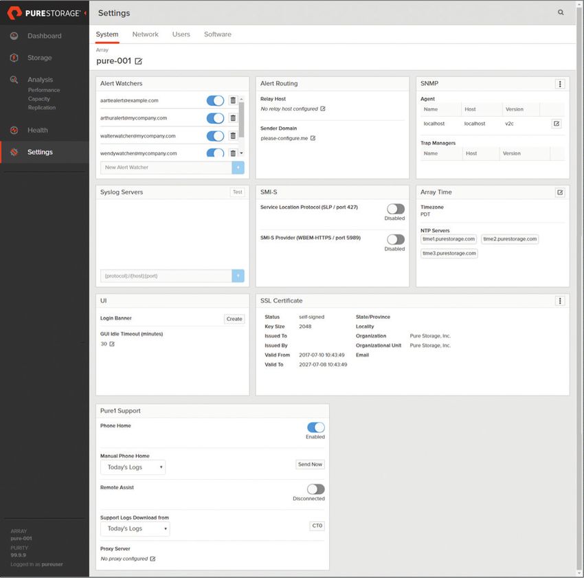
TABLE OF CONTENTS

   PURE 1 ...........................................................................................................................................4
         PURE 1 STUDY RESOURCES ...........................................................................................5
   BEST PRACTICES .......................................................................................................................5
         BEST PRACTICES STUDY RESOURCES ......................................................................6
   FLASHARRAY ..............................................................................................................................6
         GUI: ANALYSIS ....................................................................................................................9
         CAPACITY ............................................................................................................................ 10
         FLASHARRAY CONFIGURATION ................................................................................. 12
         FLASHARRAY STUDY RESOURCES ............................................................................ 14
   FLASHBLADE ........................................................................................................................... 15
         FLASHBLADE STUDY RESOURCES .............................................................................17
   SUPPORTABILITY .................................................................................................................... 18
   ALERTS ....................................................................................................................................... 19
   FLASHSTACK ............................................................................................................................. 19
         FLASHSTACK STUDY RESOURCES ............................................................................. 21
   EVERGREEN MODEL ............................................................................................................... 21
   NON-DISRUPTIVE OPERATIONS ........................................................................................ 23
   DATA REDUCTION .................................................................................................................. 24
         EVERGREEN STUDY RESOURCES .............................................................................. 25
   SUPPORT ................................................................................................................................... 26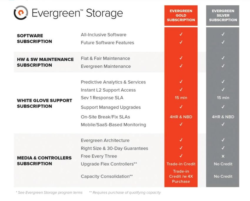
OBJECTIVE

 This study guide is designed to help you prepare for the Pure Storage
 Foundation Exam, exam number PCA_001.

AUDIENCE

 This self-study guide is intended for those who wish to undertake self-study
 or review activities before taking the actual Pure Foundation exam. The guide
 is not intended as a substitute for training or hands-on time with Pure Storage
 products.

 How to make the most of this study guide: The study guide summarizes the
 key topics on the Pure Foundation exam for you in an easy to use format. It is
 organized closely around the exam objectives but does not cover all potential
 questions from the exam and does not guarantee success on the actual
 exam. We suggest this guide be used in conjunction with our free online or
 in-person training covering FlashArray concepts and administration.

 We hope you find this guide useful in your journey towards Pure Storage
 Certification, and we welcome your feedback by sending an email to
 certification@purestorage.com.

                                                                                   3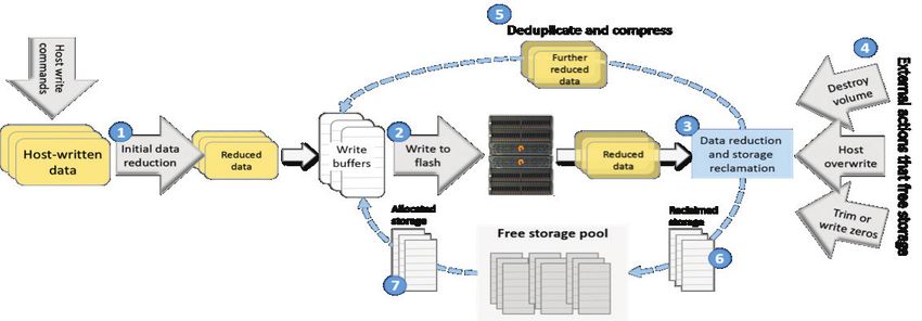
PURE1®
 PURE1 META
 Pure1 capabilities are founded on the global predictive intelligence of Pure1 Meta. Leveraging accumulated
 real-time call-home data from 1000s of cloud- connected arrays and machine learning predictive analytics,
 Meta is the AI engine for Pure1 services.

 Pure1 Manage is SaaS-based, allowing you to manage your array from any browser or from the Pure1 Mobile
 App – with nothing extra to purchase, deploy, or maintain. Just login, and from a single dashboard you can
 manage all your arrays, with full visibility on the health and performance of your storage.

 With visibility into the performance of more than 100,000 workloads, Pure1 Meta is able to generate “workload
 DNA” – workload profiles based on deep analytics of key performance characteristics. Pure1 Support
 develops “issue fingerprints” – a set of data points that are uniquely a predictor of an issue – and Meta then
 uses these fingerprints to examine incoming data from our global installed base of arrays. When Meta finds
 a match, the customer is notified, and Pure1 Support automatically opens a ticket and proactively remediates
 the situation, even before an issue has occurred

 PURE1 MANAGE
 Pure1 is the common management platform for both the Pure Storage FlashArray and FlashBlade™. Monitor all
 the vital stats of your Pure Storage fleet by logging into the new Pure1 Global Dashboard. Cloud-connected
 analytics and reporting will keep you updated on the health and performance of your storage as well as
 provide recommended actions.

 Pure1 Manage makes storage management effortless. Best of all, it’s included with every array.

 PURE1 ANALYZE
 With the rich telemetry data of 1000s of sensor-equipped arrays calling home every 30 seconds, Pure1 Meta
 is able to run machine learning models that yield accurate predictive results when applied to individual
 performance and capacity projections. These analytics replace the guesswork of the past. Whether a new
 workload will fit, whether two workloads will interact well together, and how an array’s performance and
 capacity needs will grow – the Pure1 Workload Planner uses the intelligence of Workload DNA to provide
 answers to these questions, enabling customers to truly optimize the placement of each workload.

 With volume-level analysis of migration or growth impacts, Meta can help optimize your workload placement
 as you grow. This also allows customers to align infrastructure expansion with purchasing budgets and
 schedules.

 PURE1 SUPPORT
 Pure1 Support has been a core factor in Pure delivering proven 99.9999% availability for FlashArray over
 the last two years, inclusive of maintenance and generational upgrades. Continuous monitoring, predictive
 analytics, and proactive responses have all played essential roles in keeping our customers’ data online and
 productive.
                                                                                                                  4
Pure’s proactive and predictive support experience combines top industry talent with the global predictive
intelligence of Pure1 Meta to go beyond just detecting potential issues – we aim to fix issues before they
become problems – and even before the customer notices the issue. We open the majority of support cases,
and so far we’ve resolved more than 500 Sev1 cases before they affected our customers.
With our proactive support, our team becomes your team. Our experts are keeping tabs on your arrays at all
times, helping you through upgrades, responding within a mere 15 minutes for any Sev 1 incident, and ready to
notify you if we need your assistance. If you do call us, we’ll be standing by with instant access to L2 support.
As we work with you, our goal is to resolve issues and maintain availability while providing an unmatched,
global support experience that is 100% Pure.
Pure1 Meta provides big data predictive analytics and machine learning built around our array telemetry to
identify and resolve any issues before they affect you. Our arrays send home logs every 30 seconds and we
run these logs against a growing issue fingerprint library. If any matches are found, incidents are automatically
opened and support staff are notified of a potential customer issue.
Focus Areas
• Understand Pure1 Meta capabilities and its role in conjunction to Pure1 Support and Pure1 Manage.
• Pure1’s architecture and delivery model.
• Understand Pure1’s management capabilities and platform support.
• What is “workload DNA” and its value to array management.
• Understand Pure1 Support capabilities.
• What is an “issue fingerprint” and its value to supporting an array.
PURE1® STUDY RESOURCES
• Pure1 Overview
• Pure1 Cloud and Remote Assist
• Pure1 Manage Forecast
• Pure1 Manage Analyze
• Pure1 Datasheet
BEST PRACTICES
Multipath Settings
• Round Robin, Single I/O per path
• At least two paths per host, one to each controller
5Recommendation
• Run UNMAP regularly to free deleted blocks on virtualized storage
Focus Areas
• Identify recommended settings for array multi-pathing.
• Identify how to optimize virtualized storage using UNMAP.
BEST PRACTICES STUDY RESOURCES
• Pure and Microsoft Best Practices
• Pure and VMWare Best Practices
FLASHARRAY
A FlashArray controller contains the processor and memory complex that runs the Purity//FA software, buffers
incoming data, and interfaces to storage shelves, other controllers, and hosts. FlashArray controllers are
stateless, meaning that all metadata related to the data stored in a FlashArray is contained in storage shelf
storage. Therefore, it is possible to replace the controller of an array at any time with no data loss. Data stored
in a FlashArray undergoes continuous reorganization to improve physical storage utilization and reclaim
storage occupied by data that has been superseded by host overwrite or deletion.
6TECHNICAL SPECIFICATIONS
Focus Areas
• Identify FlashArray hardware components
• Identify FlashArray software components
• Understand the meaning and importance of “Stateless” as it relates to Pure’s storage platforms
• Understand and be able to explain the “Non disruptive” service capabilities of a FlashArray
• Understand the data path for incoming read and write requests
• Understand the role of metadata and where it resides within a FlashArray
• Understand the maintenance process used my the FlashArray in managing incoming and existing data
7NVRAM
Inside the NVRAM, data is written to DRAM, which means we have unlimited endurance as well as the
performance to keep up with our PCIe interface. Of course, we need the data to stick around, so we use
supercapacitors to store energy to write the RAM contents into flash if the power fails. Since we only
write to the flash on power failure, endurance is not a concern. Everything, including the DRAM, flash and
supercapacitors is included in the NVRAM module, so there are no battery packs, cables, UPSs or any other
complexity to deal with.
Controllers talk to the FlashArray//m and FlashArray//X NVRAM modules using NVM Express (NVMe), a
standard interface for PCIe-attached storage. NVMe was designed for high performance as well as scalability
on multicore systems.
Focus Areas
• Describe how NVRAM was designed in to the FlashArray
• Understand the benefit imparted by using NVRAM in the FlashArray data path design
• Identify how the FlashArray addresses data integrity during a power failure event
• Identify the protocol and bus subsystem used by the FlashArray in communicating with the NVRAM
• Understand the benefits of NVMe over other system protocols
RAID-HA
FlashArray’s dynamic multi-level scheme for protecting against data loss due to uncorrectable read errors and
device failures. RAID-HA minimizes the impact of read error recovery, and automatically adjusts protection
parameters based on the nature of stored data and conditions within an array.
Focus Areas
• Understand the benefits and data protection optimization of Raid-HA.
• Identify what impacts Raid-HA minimize.
Platform Study Resources
• FlashArray Datasheet
• FlashArray Quick Install Guide
• Flasharray//M R2 Tech Spec
• Flasharray//X70 Tech Spec
8GUI: ANALYSIS
By default, Purity//FA displays the performance details for the entire array. To analyze the performance
details of specific volumes, click the Volumes sub-tab along the top of the Performance page, select Volumes
from the drop-down list, and select the volumes you want to analyze. To analyze the performance details of
volumes within specific volume groups, click the Volumes sub-tab along the top of the Performance page,
select Volume Groups from the drop-down list, and select the volume groups you want to analyze. You can
analyze up to five volumes and volume groups at one time.
Click Clear All to clear the selections and display the performance details of all volumes again. The Analysis
> Performance page includes Latency, IOPS, and Bandwidth charts. The point-in-time pop-ups in each of the
performance charts display the following values:
LATENCY
The Latency chart displays the average latency times for various operations.
• SAN - Average time, measured in milliseconds, required to transfer data between the initiator and the
array. SAN times are only displayed in graphs of one I/O type, such as Read or Write.
• Read Latency (R) - Average arrival-to-completion time, measured in milliseconds, for a read operation.
• Write Latency (W) - Average arrival-to-completion time, measured in milliseconds, for a write operation.
• Mirrored Write Latency (MW) - Average arrival-to-completion time, measured in milliseconds, for a write
operation. Represents the sum of writes from hosts into the volume’s pod and from remote arrays that
synchronously replicate into the volume’s pod.
• Queue Depth - Average number of queued I/O requests for all volumes.
IOPS
The IOPS (Input/output Operations Per Second) chart displays I/O requests processed per second by the
array. This metric counts requests per second, regardless of how much or how little data is transferred in
each.
• Read IOPS (R) - Number of read requests processed per second.
• Write IOPS (W) - Number of write requests processed per second.
• Mirrored Write IOPS (MW) - Number of write requests processed per second. Represents the sum of
writes from hosts into the volume’s pod and from remote arrays that synchronously replicate into the
volume’s pod.
9BANDWIDTH
The Bandwidth chart displays the number of bytes transferred per second to and from all file systems. The
data is counted in its expanded form rather than the reduced form stored in the array to truly reflect what is
transferred over the storage network. Metadata bandwidth is not included in these numbers.
• Read Bandwidth (R) - Number of bytes read per second.
• Write Bandwidth (W) - Number of bytes written per second.
• Mirrored Write Bandwidth (MW) - Number of bytes written into the volume’s pod per second. Represents
the sum of writes from hosts into the volume’s pod and from remote arrays that synchronously replicate
into the volume’s pod.
Focus Areas
• Identify where and what FlashArray details Purity provides via the GUI.
• Understand the analysis features and capabilities of Purity.
• Identify how and where to find analysis details on Volumes.
• Identify what performance values are detailed.
• Identify values which are measured as it relates to latency.
• Understand how often are I/O requests processed tracked.
• Identify values which are measured as it relates to IOPS.
• Identify what data size is used in viewing bandwidth related information tracked.
• How does the Analysis reporting take into account data reduction and metadata.
• Identify what values are measured as it relates to Bandwidth.
CAPACITY
The Array Capacity chart displays the amount of usable physical storage on the array and the amount of
storage occupied by data and metadata. The data point fluctuations represent changes in physical storage
consumed by a volume.
In the Array Capacity chart, the point-in-time pop-up displays the following metrics:
• Empty Space: Unused space available for allocation.
• System: Physical space occupied by internal array metadata.
• Shared Space: Physical space occupied by deduplicated data, meaning that the space is shared with
other volumes and snapshots as a result of data deduplication.
• Snapshots: Physical space occupied by data unique to one or more snapshots.
10• Volumes: Physical space occupied by volume data that is not shared between volumes, excluding array
metadata and snapshots.
• Used: Physical storage space occupied by volume, snapshot, shared space, and system data.
• Usable Capacity: Total physical usable space on the array.
• Data Reduction: Ratio of mapped sectors within a volume versus the amount of physical space the data
occupies after data compression and deduplication. The data reduction ratio does not include thin
provisioning savings.
The Host Capacity chart displays the provisioned size of all selected volumes. In the Host Capacity chart, the
point-in-time pop-up displays the following metrics:
• Provisioned: Total provisioned size of all volumes. Represents storage capacity reported to hosts. The
Settings > System page displays and manages the general attributes of the FlashArray array.
11FLASHARRAY CONFIGURATION
The following array-specific tasks can be performed through the Purity//FA GUI:
• Display array health through the Health > Hardware page.
• Monitor capacity, storage consumption, and performance (latency, IOPS, bandwidth) metrics through the
Analysis page.
Change the array name through the Storage > Array page. The same tasks can also be performed through the
CLI purearray command.
Focus Areas
• Identify the array specific tasks that can be performed through the Purity FlashArray GUI.
• Identify how to view array health.
• Identify how to view usable capacity, storage consumption and performance metrics.
• Identify how to change the array name.
VOLUMES
FlashArrays eliminate drive-oriented concepts such as RAID groups and spare drives that are common
with disk arrays. Purity//FA treats the entire storage capacity of all flash modules in an array as a single
homogeneous pool from which it allocates storage only when hosts write data to volumes created by
administrators. Creating a FlashArray volume, therefore, only requires a volume name, to be used in
administrative operations and displays, and a provisioned size.
1. Select Storage > Volumes.
2. In the Volumes panel, click the menu icon and select Create... The Create Volume dialog box appears.
3. In the Container field, select the root location, pod, or volume group to where the volume will be
created.
4. In the Name field, type the name of the new volume.
5. In the Provisioned Size field, specify the provisioned (virtual) size number and size unit. The volume
size must be between one megabyte and four petabytes. The provisioned size is reported to hosts.
6. Click Create.
Creating a volume creates persistent data structures in the array but does not allocate any physical storage.
Purity//FA allocates physical storage only when hosts write data. Volume creation is therefore nearly
instantaneous. Volumes do not consume physical storage until data is actually written to them, so volume
creation has no immediate effect on an array’s physical storage consumption.
12Rename a volume to change the name by which Purity//FA identifies the volume in administrative operations
and displays. The new volume name is effective immediately and the old name is no longer recognized in CLI,
GUI, or REST interactions.
Resize an existing volume to change the virtual capacity of the volume as perceived by the hosts. The volume
size changes are immediately visible to connected hosts. If you decrease (truncate) the volume size, Purity//
FA automatically takes an undo snapshot of the volume. The undo snapshot enters a 24-hour eradication
pending period, after which time the snapshot is destroyed. During the 24-hour pending period, the undo
snapshot can be viewed, recovered, or permanently eradicated through the Destroyed Volumes folder.
Increasing the size of a truncated volume will not restore any data that is lost when the volume was first
truncated.
Copy a volume to create a new volume or overwrite an existing one. After you copy a volume, the source of
the new or overwritten volume is set to the name of the originating volume.
Destroy a volume if it is no longer needed. When you destroy a volume, Purity//FA automatically takes an
undo snapshot of the volume. The undo snapshot enters a 24-hour eradication pending period. During the
24-hour pending period, the undo snapshot can be viewed, recovered, or permanently eradicated through
the Destroyed Volumes folder. Eradicating a volume completely obliterates the data within the volume,
allowing Purity//FA to reclaim the storage space occupied by the data. After the 24- hour pending period, the
undo snapshot is completely eradicated and can no longer be recovered.
Focus Areas
• Understand how Purity manages the entire storage capacity on an array.
• Identify the steps of how to create a volume in Purity.
• Understand how creating volumes impact physical storage consumption.
• Understand how volume naming conventions function within Purity.
• Understand how resizing a volume will impact what the array and hosts will see.
• Identify how to undo a resize event without data loss.
• Understand the retention policies for resize changes, deleted snapshots and volumes.
• Identify how to create and copy volumes.
HOSTS
The host organizes the storage network addresses - the Fibre Channel worldwide names (WWNs) or iSCSI
qualified names (IQNs) - that identify the host computer initiators. The host communicates with the array
through the Fibre Channel or iSCSI ports. The array accepts and responds to commands received on any of
its ports from any of the WWNs or IQNs associated with a host. Purity//FA will not create a host if:
131. The specified name is already associated with another host in the array.
2. Any of the specified WWNs or IQNs is already associated with an existing host in the array.
3. The creation of the host would exceed the limit of concurrent hosts, or the creation of the WWN or IQN
would exceed the limit of concurrent initiators.
Purity//FA will not delete a host if:
• The host has private connections to one or more volumes.
Purity//FA will not associate a WWN or IQN with a host if:
• The creation of the WWN or IQN would exceed the maximum number of concurrent initiators.
• The specified WWN or IQN is already associated with another host on the array. Hosts are configured
through the GUI (Storage > Hosts) and CLI (purehost command).
Host-volume connections are performed through the GUI (Storage > Hosts and Storage > Volumes) and CLI
(purehgroup connect, purehost connect and purevol connect commands).
The Connections page displays connectivity details between the Purity//FA hosts and the array ports. The
Host Connections pane displays a list of hosts, the connectivity status of each host, and the number of
initiator ports associated with each host. Connectivity statuses range from “None”, where the host does not
have any paths to any target ports, to “Redundant”, where the host has the same number of paths from every
initiator to every target port on both controllers.
Host connections and target ports are displayed through the GUI (select Health > Connections) and CLI
(pureport list, purehost list --all, and purevol list --all commands).
Focus Areas
• Understand host and array fiber channel configuration requirements.
• Understand how the handshake process between the host and the array.
• Identify configuration conditions that can lead to the array aborting host creation.
• Identify conditions that would prevent Purity from deleting a host.
• Identify conditions that would prevent Purity from associating a WWN or IQN with a host.
• Identify how to conduct a host-volume connection via the GUI.
• Identify how to view host connection status.
• Identify what host connectivity status states exist.
FlashArray Study Resources
• FlashArray User Guide
14FLASHBLADE™
CONNECTIVITY
8x 40Gb/s or 32x 10Gb/s Ethernet ports / chassis
SCALE-OUT DIRECTFLASH™ + COMPUTE
• Ultra-low latency 17 and 52TB capacity options that can be hot-plugged into the system for expansion
and performance.
• FlashBlade delivers industry-leading throughput, IOPS, latency, and capacity – in typically 20x less
space and 10x less power and cooling.
• Minimum configuration: 7 blades.
• Maximum configuration: 15 blades.
• Each blade integrates compute (Intel system-on-a-chip), storage (DirectFlash), and NVRAM.
• Blades are interconnected via dual fabric modules.
SCALE-OUT STORAGE SOFTWARE
Purity//FB software is the heart of FlashBlade, implementing its scale-out storage capabilities, services and
management.
SOFTWARE- DEFINED NETWORKING
Includes a built in 40Gb Ethernet fabric providing a total network bandwidth of 320Gb/s for the chassis.
Focus Areas
• Understand the architecture and design of the FlashBlade chassis.
• Understand the architecture and design of the FlashBlade Blade.
• Identify FlashBlade’s network connectivity configurations.
• Identify FlashBlade’s chassis networking performance specifications.
• Identify FlashBlade’s capacity options, minimum and maximum configurations.
• Understand Purity’s role as scale-out storage software.
15GUI
DASHBOARD
Represents a graphical overview of the array, including hardware status, recent alerts, storage capacity, and
input/output (I/O) performance metrics.
STORAGE
Displays a list of file systems on the array and its attributes, including provisioned size, capacity usage details,
and export rules. Exporting a file system requires at least one valid data virtual IP address (data vip). Data vips
are configured through the Settings > Network page.
HEALTH
Displays array health including alerts, hardware status, and parity.
ANALYSIS
Displays historical array information, including storage capacity and I/O performance metrics, from various
viewpoints.
SETTINGS
Displays array-wide system and network settings. Manage array-wide components, including network
interfaces, system time, connectivity and connection configurations, and alert settings.
Focus Areas
• Identify what information is available via the FlashBlade GUI Dashboard.
• Identify what information is available via the FlashBlade storage panel.
• Understand the requirements for exporting a file system.
• Understand how to configure Data VIPs.
• Identify what information is available via the FlashBlade Health panel.
• Identify what information is available via the FlashBlade Analysis panel.
• Identify what configuration options are available via the FlashBlade settings panel.
16CAPACITY
The capacity panel displays the percentage of array space occupied by file system data. The percentage
value in the center of the wheel is calculated as Used/Total. The capacity data is broken down into the
following components:
FILE SYSTEMS
Amount of space that the written data occupies on the array after reduction via data compression.
OBJECT STORE
Amount of space that the written data occupies on the array’s buckets after reduction via data compression.
EMPTY
Unused space.
USED
Amount of space that the written data occupies on the array after reduction via data compression.
TOTAL
Total usable capacity of the array.
DATA REDUCTION
Ratio of the size of the written data versus the amount of space the data occupies after data compression.
Focus Areas
• Identify how occupied capacity is determined and presented via the capacity panel.
• Identify what capacity data components are viewable in the capacity panel.
FlashBlade Study Resources
• FlashBlade User Guide
• Flashblade Datasheet
17SUPPORTABILITY
An alert is triggered when there is an unexpected change to the array or to one of the Purity//FA hardware or
software components. Alerts are categorized by severity level as critical, warning, or informational.
Alerts are displayed in the GUI and CLI. Alerts are also logged and transmitted to Pure Storage Support via
the phone home facility. Furthermore, alerts can be sent as messages to designated email addresses and as
Simple Network Management Protocol-based (SNMP) traps and informs to SNMP managers.
PHONE HOME FACILITY
The phone home facility provides a secure direct link between the array and the Pure Storage Support team.
The link is used to transmit log contents and alert messages to the Pure Storage Support team. Optionally
configure the proxy host for HTTPS communication.
The phone home facility is managed through the GUI (Settings > System) and CLI (purearray command). The
audit trail represents a chronological history of the Purity//FA GUI, Purity//FA CLI, or REST API operations
that a user has performed to modify the configuration of the array. Audit trails are displayed through the GUI
(Settings > Users) and the CLI (puremessage command).
REMOTE ASSIST
Remote assist sessions are controlled by the array administrator, who opens a secure channel between the
array and Pure Storage Support, making it possible for a technician to log in to the array. The administrator
can check session status and close the channel at any time.
Remote assist sessions are opened and closed through the GUI (Settings > System) and CLI (purearray
remoteassist command).
Configure the network connection attributes, including the interface, netmask, and gateway IP addresses,
and the MTU. Ethernet and bond interface IP addresses and netmasks are set explicitly, along with the
corresponding netmasks. DHCP mode is not supported. The array requires a minimum of three IP addresses
configured: one for each physical controller management port and one for the multi-homed VIP.
Network interfaces and DNS settings are configured through the GUI (Settings > Network) and CLI
(purenetwork command for network interfaces, and puredns for DNS settings). Ethernet interfaces support
one of three services: replication, management, or iSCSI.
Focus Areas
• Understand the functionality and use of the phone home facility feature.
• Identify where to configure the phone home facility.
• Understand what details are captured in the audit trail capability.
• Understand the functionality and use of the remote assist feature.
18• Identify how to initiate a remote assist session.
• Identify how to configure the remote assist feature.
• Identify configuration requirements for remote assist.
ALERTS
The alert icons that appear to the far right of the title bar indicate the number of recent Warning and Critical
alerts, respectively. A recent alert represents one that Purity//FA saw within the past 24 hours and still
considers an open issue that requires attention. Click anywhere in an alert row to display additional alert
details. To analyze the alerts in more detail, select Health > Alerts.
Critical (red) alerts are typically triggered by service interruptions, major performance issues, or risk of data
loss, and require immediate attention. For example, Purity//FB triggers a critical alert if a FlashBlade has been
removed from the chassis. Purity//FA will trigger a critical alert if capacity utilization has reached 100%. This
event is deemed critical because the array may begin throttling write requests, increasing latency.
Warning (yellow) alerts are of low to medium severity and require attention, though not as urgently as critical
alerts. For example, Purity//FB triggers a warning alert if it detects an unhealthy FlashBlade that is still
processing data. Purity//FA triggers a warning alert if capacity utilization has reached 90%.
Informational (blue) alerts inform users of a general behavior change and require no action. For example,
Purity//FB triggers an informational alert if the NFS service is unhealthy. Purity//FA triggers an informational
alert if capacity utilization has reached 80%.
Focus Areas
• Identify when alerts are triggered and support process that is initiated.
• Identify the alert severity categories.
• Identify where alerts are displayed.
• Identify how to configure alert notifications.
• Identify how to view details on alert notifications.
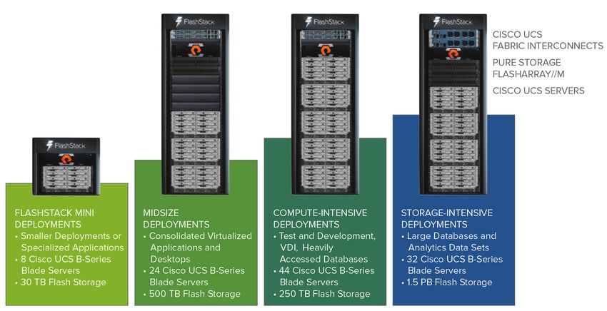
FLASHSTACK™
FlashStack is an excellent platform for delivering mission-critical workloads and empowering users by building
on extensible, continuously available, Cisco validated architecture. The FlashStack architecture is designed
for resilience and high availability to help keep important workloads and applications online and available.
The design combines individual components with high availability into a single, redundant architecture and
includes tools for simplified backup and recovery operations.
19With FlashStack, IT organizations can upgrade capacity without downtime and deploy cloud-like capabilities
to help ensure constant access to data across the organization. Now IT administrators can avoid the rip-and-
replace cycle of traditional infrastructure ownership and use familiar, integrated tools to manage the entire
data center stack right out of the box.
Hardware Components:
• Cisco UCS high-density, modular, policy-based computing platform
a) Scales seamlessly from 1 to 160 servers, including both blade and rack servers
b) Interconnected with Cisco SingleConnect technology through fabric interconnects, fabric extenders,
and Cisco virtual interface cards (VICs)
• Cisco Nexus® Family switches and Cisco MDS 9000 Family Fibre Channel directors
• Pure Storage FlashArray//M and FlashArray//X
Focus Areas
• Understand the joint value proposition of FlashStack.
• Identify the components that comprise a FlashStack Converged Infrastructure platform.
• Identify the FlashStack maximum scale out configuration.
• Identify the Cisco SingleConnect technology components use to interconnect FlashStack.
20FlashStack Study Resources
• FlashStack Brief
EVERGREEN™ MODEL
Evergreen Subscriptions give you all-inclusive access to our software, today and into the future, without
having to pay extra for your existing storage footprint. It’s as simple as that. Our customers have already
benefited tremendously as we’ve rolled out major enhancements over the years, and there are plenty more to
come.
Tired of big expenses hitting your budget at inconvenient times? Or having to deal with increasingly higher
costs to own aging storage? Evergreen Subscriptions give you predictably flat maintenance rates over time.
They’ll never go up, and they may even go down. And, we’ll replace any problematic hardware or software
with like or better for as long as you are under our subscription.
Evergreen Subscriptions give you a full complement of high end services to make sure your array runs fast
and smoothly. Our Global Insight Engine in the Pure1® cloud powers our Predictive Analytics, which are
optimized to find and fix potential issues – before they become real issues. Our experts are keeping tabs on
your arrays at all times, helping you through upgrades, responding within a mere 15 minutes for any Sev 1
incident, and ready to notify you if we need your assistance. If you do call us, we’ll be standing by with instant
access to L2 support – no L1 hassles and repeated explanations that waste time and money. It’s practically
like a managed service included in your subscription.
Our standard Evergreen Gold subscription completes the experience with a range of programs to modernize
both controllers and flash media – without re-buys. Evergreen Gold includes next-generation controllers with
every three-year renewal. With Evergreen Gold’s Upgrade Flex bundles, anytime you expand FlashArray
with a qualifying capacity purchase you receive trade-in credit for your existing controllers towards our most
modern controllers – even if they are next-generation. Either way, your controllers will stay modern. And for
flash media, any capacity expansions not tied to an Upgrade Flex qualify for trade-in credit for a portion of
your existing, less dense flash. The end result? No repurchases of TBs you already own even as your whole
FlashArray modernizes. That’s what we mean by Evergreen.
21Focus Areas
• Understand the value proposition of the Evergreen Model in TCO.
• Identify how software licensing works in the Evergreen Model.
• Identify how features and upgrades work in the Evergreen Model.
• Identify how maintenance rates work in the Evergreen Model.
• Identify the support benefits included in the Evergreen Model.
• Identify the subscription tiers in the Evergreen Model.
22NON-DISRUPTIVE OPERATIONS
ACTIVE/ACTIVE HIGH AVAILABILITY
Clustered controller design allows for the complete failure of a controller or any controller component without
impacting operations.
MIRRORED NV-RAM
Write IOs are persisted to NV-RAM modules, ensuring in-flight writes are protected against power loss and
device failure.
HOT-SWAPPABLE COMPONENTS
Flash Modules, NV- RAM Modules, and controllers are hot- swappable for continuous operation, even when
recovering from a failure.
STATELESS CONTROLLER ARCHITECTURE
Simply unplug a failed controller, cable up a new one, and the FlashArray is back to full- availability, all without
any performance loss.
NON-DISRUPTIVE CAPACITY EXPANSION
Flash capacity can be added online and becomes instantly available.
NON-DISRUPTIVE CONTROLLER UPGRADES
Performance can be expanded, even across generations, with no downtime.
NON-DISRUPTIVE HARDWARE REPLACEMENT
Maintenance or replacement of any failed component is performed online.
NON-DISRUPTIVE SOFTWARE UPGRADES
New features and flash technology advancements are easily enabled with software upgrades that are not
only non- disruptive to availability, but also to the performance of applications.
Although the IO handling of the FlashArray is active/active from all ports on both controllers, we reserve the
performance of one controller on the backend. This enables all maintenance operations to be performed with
zero performance loss.
Focus Areas
• Identify how the controller design enables non-disruptive operations.
• Understand how write IOs are processed and are protected.
23• Identify which components are hot swappable.
• Understand the importance of stateless architecture in system recovery and upgrades.
• Understand how capacity can be added non-disruptively.
• Understand how storage performance can expanded non-disruptively.
• Understand how software upgrades are conducted non-disruptively.
• Understand the performance impact of the maintenance operations.
DATA REDUCTION
Many vendors will include thin provisioning or snap savings in their DR numbers to, well, make up for
some lackluster core DR. Or they’ll talk about configuring DR per volume, which is really just a way to mask
performance impacts. We don’t – we tell you what our inline and always-on DR technologies are delivering,
globally across our entire installed base, and separately what the numbers look like with thin provisioning
included.
PATTERN REMOVAL
Pattern removal identifies and removes repetitive binary patterns, including zeroes. In addition to capacity
savings, pattern removal reduces the volume of data to be processed by the dedupe scanner and
compression engine.
512B ALIGNED, VARIABLE DEDUPE
High-performance, inline deduplication operates on a 512- byte aligned, variable block size range from
4 - 32K. Only unique blocks of data are saved on flash – removing even the duplicates that fixed-block
architectures miss. Best of all, these savings are delivered without requiring any tuning.
INLINE COMPRESSION
Inline compression reduces data to use less capacity than the original format. Append-only write layout
and variable addressing optimize compression savings by removing the wasted space that fixed-block
architectures introduce. Combined with Deep Reduction, compression delivers 2 - 4x data reduction, and is
the primary form of data reduction for databases.
DEEP REDUCTION
Purity Reduce doesn’t stop at inline compression – additional, heavier-weight compression algorithms are
applied post- process that increase the savings on data that was compressed inline. Most other all-flash
products lack the use of multiple compression algorithms, and simply miss these savings.
24COPY REDUCTION
Copying data on a FlashArray only involves metadata! Leveraging the data reduction engine, Purity provides
instant pre-deduplicated copies of data for snapshots, clones, replication, and xCopy commands.
Focus Areas
• Understand the impact of thin provisioning and snapshot savings in representing total data reduction.
• Understand how Pure implements pattern removal to reduce overall data footprint.
• Understand the impact of 512B aligned inline deduplication.
• Understand the impact of inline compression in using less capacity than the original format.
• Understand when and how Purity uses deep reduction.
• Understand how copy reduction leverages metadata.
Evergreen Study Resources
• Evergreen Efficiency
• Evergreen Program
• Purity Reliability
• Purity Data Reduction
25SUPPORT
For information on Pure Storage’s certification programs, visit www.examslocal.com. To contact us, please
send an email to certification@purestorage.com.
Pure Storage, Inc.
Twitter: @purestorage
www.purestorage.com
650 Castro Street, Suite #260
Mountain View, CA 94041
T: 650-290-6088
F: 650-625-9667
Sales: sales@purestorage.com
Support: support@purestorage.com
Media: pr@purestorage.com
© 2018 Pure Storage, Inc. All rights reserved.
ps_sg_fasupport-pro-employee-exam2018_04You can also read