Simple and Scalable Streaming: The GRETA Data Pipeline
←
→
Page content transcription
If your browser does not render page correctly, please read the page content below
EPJ Web of Conferences 251, 04018 (2021)                                      https://doi.org/10.1051/epjconf/202125104018
CHEP 2021

      Simple and Scalable Streaming: The GRETA Data Pipeline
      ∗

      Mario Cromaz1,∗∗ , Eli Dart2,∗∗∗ , Eric Pouyoul2,∗∗∗∗ , and Gustav R. Jansen3,†
      1
        Nuclear Science Division, Lawrence Berkeley National Laboratory, CA, USA
      2
        Energy Sciences Network (ESnet), Lawrence Berkeley National Laboratory, CA, USA
      3
        National Center for Computational Sciences, Oak Ridge National Laboratory, TN, USA

                   Abstract. The Gamma Ray Energy Tracking Array (GRETA) is a state of the
                   art gamma-ray spectrometer being built at Lawrence Berkeley National Labora-
                   tory to be first sited at the Facility for Rare Isotope Beams (FRIB) at Michigan
                   State University. A key design requirement for the spectrometer is to perform
                   gamma-ray tracking in near real time. To meet this requirement we have used an
                   inline, streaming approach to signal processing in the GRETA data acquisition
                   system, using a GPU-equipped computing cluster. The data stream will reach
                   480 thousand events per second at an aggregate data rate of 4 gigabytes per sec-
                   ond at full design capacity. We have been able to simplify the architecture of the
                   streaming system greatly by interfacing the FPGA-based detector electronics
                   with the computing cluster using standard network technology. A set of high-
                   performance software components to implement queuing, flow control, event
                   processing and event building have been developed, all in a streaming environ-
          ∗ This work was supported by the Director, Office of Science, Office of Advanced Scientific Computing Research
      (ASCR), of the U.S. Department of Energy under Contract No. DE-AC02-05CH11231.
         This manuscript has been authored by an author at Lawrence Berkeley National Laboratory under Contract No.
      DE-AC02-05CH11231 with the U.S. Department of Energy. The U.S. Government retains, and the publisher, by
      accepting the article for publication, acknowledges, that the U.S. Government retains a non-exclusive, paid-up,
      irrevocable, world-wide license to publish or reproduce the published form of this manuscript, or allow others to do
      so, for U.S. Government purposes.
         Notice: "This manuscript has been authored by UT-Battelle, LLC under Contract No. DE-AC05-00OR22725 with
      the U.S. Department of Energy. The United States Government retains and the publisher, by accepting the article for
      publication, acknowledges that the United States Government retains a non-exclusive, paid-up, irrevocable, world-
      wide license to publish or reproduce the published form of this manuscript, or allow others to do so, for United States
      Government purposes. The Department of Energy will provide public access to these results of federally sponsored
      research in accordance with the DOE Public Access Plan (http://energy.gov/downloads/doe-public-access-plan)."
         Disclaimer: This document was prepared as an account of work sponsored by the United States Government.
      While this document is believed to contain correct information, neither the United States Government nor any agency
      thereof, nor the Regents of the University of California, nor any of their employees, makes any warranty, express
      or implied, or assumes any legal responsibility for the accuracy, completeness, or usefulness of any information,
      apparatus, product, or process disclosed, or represents that its use would not infringe privately owned rights. Ref-
      erence herein to any specific commercial product, process, or service by its trade name, trademark, manufacturer,
      or otherwise, does not necessarily constitute or imply its endorsement, recommendation, or favoring by the United
      States Government or any agency thereof, or the Regents of the University of California. The views and opinions
      of authors expressed herein do not necessarily state or reflect those of the United States Government or any agency
      thereof or the Regents of the University of California.
         ∗∗ e-mail: mcromaz@lbl.gov
        ∗∗∗ e-mail: dart@es.net
      ∗∗∗∗ e-mail: lomax@es.net
          † e-mail: jansengr@ornl.gov

© The Authors, published by EDP Sciences. This is an open access article distributed under the terms of the Creative Commons
Attribution License 4.0 (http://creativecommons.org/licenses/by/4.0/).
EPJ Web of Conferences 251, 04018 (2021) https://doi.org/10.1051/epjconf/202125104018
CHEP 2021
ment which matches detector performance. Prototypes of all high-performance
components have been completed and meet design specifications.
1 Introduction
The Gamma-Ray Energy Tracking Array (GRETA)[1] is a large scale gamma-ray spectrome-
ter that will be used to perform nuclear structure and nuclear astrophysics studies at facilities
such as the Facility for Rare Isotope Beams (FRIB)[2] and at the Argonne Tandem Linear
Accelerator System (ATLAS)[3]. This detector uses gamma-ray tracking[4, 5], a new tech-
nology where the interaction points of the incident scattering gamma-rays can be localized
in the HPGe detector volume to mm precision so that Compton tracking can be performed.
This allows for the device to have very high gamma-ray efficiency while maintaining a good
peak-to-total ratio, thus extending the physics reach of the instrument.
A unique aspect of GRETA is the need to process the data online with a latency of less
than ten seconds. The requirement is driven by the relatively short duration (1-5 days) of
the experiments, often with multiple beam and target combinations that results in constant
changes to the experimental setups and device configurations. To make optimal use of the
available machine time, experimenters must be able to debug and optimize their experiments
in real time, without resorting to offline analysis. Meeting this latency requirement is a chal-
lenging problem as the data analysis procedures to locate the interaction points of the gamma
rays in the HPGe volume from the raw digitized waveforms to support tracking are both data
intensive and computationally complex. To address this we have adopted a streaming data
acquisition system which we believe generalizes to a large class of event-based experiments.
Furthermore the data transport aspects of the system are abstracted from the specific analysis
procedures. Our results on prototype implementations indicate that the design is both feasible
and scalable.
Streaming architectures when applied to physics instruments can be complex. Previ-
ous work carried out on the GRETINA[6] detector, a currently-operating demonstrator for
gamma-ray tracking technology, required a complex hardware and network infrastructure
that included purpose-built VME-based digitizers, embedded readout computers, custom pro-
tocols for communication, and static provisioning of the cluster resources. Moving from
GRETINA to GRETA, there was a clear need for higher throughput, but also a need for a
simpler, more maintainable design that allows for dynamic provisioning of computing re-
sources. Our approach to this problem has been to apply standards-based networking as early
in the data acquisition process as possible (at the level of front-end FPGAs) and leverage
widely used communication protocols and libraries.
In this paper we will discuss the GRETA network environment, and then the architecture
of the GRETA data pipeline and its requirements. This will be followed by a detailed descrip-
tion of the prototypes of the primary data pipeline components: the forward buffer, the event
processing component, and the event builder, as well as the common communication library
which binds them together. Benchmark results carried out on the prototypes of these three
components using realistic traffic simulations will be given to show the performance scope of
the system. We will end with a brief discussion of future work and possible generalizations
of the system to other use cases.
2 The GRETA Network Environment
All of the data pipeline components, as well as the control system components, of the GRETA
environment are interconnected by a standards-based high-performance network. GRETA
2EPJ Web of Conferences 251, 04018 (2021) https://doi.org/10.1051/epjconf/202125104018
CHEP 2021
has an unusual requirement in that it is assumed the instrument can move between experi-
mental facilities as is the case with its predecessor GRETINA. This requires that the network
be self-contained, with minimal reconfiguration required when moving GRETA between host
facilities. A further requirement is that GRETA can operate in the presence of external net-
work connectivity interruptions. This requires that the GRETA network environment self-
host a number of standard services (e.g. DNS, NTP, local Docker registry, etc.). In short,
GRETA must be self-sufficient for all services required for experiment operation.
Sites hosting GRETA will have two primary physical locations for computing hardware
deployment: one is the experiment hall, where the detectors and electronics are deployed,
and the other is a facility computing room, where the Forward Buffers, Event Builder, Event
Processing Cluster, storage systems, cluster management, and other servers are deployed.
Switches which receive high-speed UDP traffic from forward buffers are deeply buffered to
reduce the probability of packet loss due to incast congestion. The controls network and
data network are separate from each other (so that neither interferes with the other), but both
networks are present in both locations. The two locations are connected with two redundant
link pairs, one for the controls network and one for the data network. In addition, in the
computing cluster area there is a management network for managing the Linux systems in
that part of the network. The controls network uses the EPICS[7] control system. A full
description of the GRETA control systems will be published in a future paper.
Display Output
Display Output (Operator)
Science
(Operator) 120 digitizer modules External Network
DMZ
(on the detector), 10G
4 aux detector 4x10G
1x25G
hosts, 10G 1x10G
2 operator 1x10G
1 data transfer
console 1 bastion
hosts, 10G host, 10G
DTN
120x10G 4x10G
1 Internet
2x10G 4x1G 1x10G
Services Host, 1x10G 1x25G
1x1G
10G 1x1G 1x1G 1x10G
30 filter boards, 25G
30x25G 2x100G 45x10G
30x10G 2x10G 45x1G
1x10G
1x1G 1x1G
16 trigger/timing 1 configuration/ 4x100G
boards, 1G 1x10G 45 cluster
control host, 10G 4x1G
1x10G 2x1G 1x1G 3x10G nodes, 10G
1x1G 3x1G 2x10G
2x1G 1x100G
1 configuration 1x10G 1x1G
database host, 10G 1x1G 2x25G
2x1G
4 forward buffer
1x100G nodes, 100G
1x10G
1x1G
1 primary trigger/ 1 mechanical 2 HV/LV 1x1G
3 EPICS
timing board, 10G PLC, 1G controllers, 1G
servers, 10G
1 prompt analysis
host, 10G 1 systems data
1G storage system
Data Connections 1 event builder
2x10G
10G Control Connections 1 cluster control node, 100G
Management Connections node, 10G
25G 1 user data
100G storage system,
GRETA Physical Network 1 archiver
2x25G node, 100G
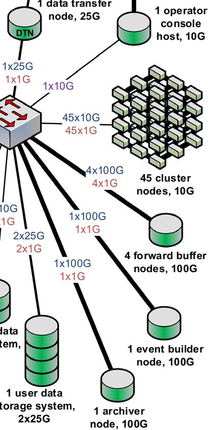
Figure 1. A physical map of the future GRETA network design. Connection counts, as well as control,
data, and management networks are shown.
As is the case with any modern computing environment, cybersecurity is of great impor-
tance to GRETA. Because the timing of future security vulnerabilities cannot be determined,
and the GRETA data pipeline must be able to operate during experiments, the security ar-
chitecture assumes that security vulnerabilities are present in one or more systems within the
3EPJ Web of Conferences 251, 04018 (2021) https://doi.org/10.1051/epjconf/202125104018
CHEP 2021
GRETA environment, and that GRETA must be able to operate safely despite the vulnerabil-
ities. The primary mechanism for protecting the GRETA environment is network isolation.
This means that only a small set of specific systems are allowed to connect to the Internet
at all, and those systems are not part of the data pipeline (for example, bastion hosts for re-
mote login by system administrators are allowed, but these run a small set of specific services
with a tight security policy, and are not involved in experiment operation or data processing).
There is one exception to this, which is the computing system used to support an auxiliary
detector. The approach taken here is to limit privilege and restrict services available to the
auxiliary detectors to a minimum (data transfer to a Forward Buffer and run control mes-
saging) on GRETA-facing interfaces. This security design is also well-aligned with the goal
of reducing the complexity of re-deploying GRETA when moving between sites. The only
systems that need to be reconfigured when GRETA is moved are the few systems that have
management interfaces, and the Science DMZ[8] interface of the Data Transfer Node.
3 The GRETA Data Pipeline
3.1 Functional components
The GRETA data pipeline is composed of a series of components, each fulfilling its role in the
transport and processing of data. The streaming design of the data pipeline means that data
processing is done online, before the data are written to storage. The interface between the
detector electronics (specifically the FPGA-based Signal Filter Boards) and the data pipeline
is standard Ethernet[9]. In fact, the entire computing environment uses standard systems and
networking technologies which are commonplace in today’s world, including software capa-
bilities such as Docker containers to simplify deployment and open source software to reduce
development effort. This allows GRETA to take advantage of billions of dollars of investment
in performance, reliability, and economies of scale which have followed the dramatic expan-
sion of the Internet.
Figure 2 provides a graphical representation of the data flow through the pipeline. The
data is sent from the Signal Filter Boards to the Forward Buffers. The Forward Buffers,
hosted on standard servers with high-speed interfaces, receive the data and place it in queues
(the internals of the Forward Buffer are further described in Section 3.2), which allows the
Event Processing Cluster to self-schedule its tasks by fetching data asynchronously from the
Forward Buffers. This is a key architectural point: if the Forward Buffers were not present
then the Signal Filter Boards, which are built around FPGAs, would have to distribute their
data to the individual cluster nodes. FPGAs are not well-suited to buffering data, or managing
many network connections to a set of cluster nodes. However, the FPGAs in the Signal Filter
Boards can easily send stateless messages to high-performance Forward Buffer nodes, the
Forward Buffer nodes can easily manage large memory buffers to ensure that no data is lost,
and the individual Event Processing Cluster nodes can easily fetch data to process when
they have available cycles. Both the Signal Filter Boards and the Event Processing Cluster
can thus operate asynchronously. By incorporating high-performance networking into the
Signal Filter Boards, the complexity of the FPGA programming can be dramatically reduced
- the Forward Buffers provide the necessary adaptation between the Signal Filter Boards and
the cluster. The Forward Buffer component also allows data from auxiliary detectors to be
incorporated into the data flow - the auxiliary detector sends its data to a Forward Buffer, and
the Forward Buffer serves it to the Event Processing Cluster just as it would serve the GRETA
HPGe data.
The cluster nodes process the data to solve for the position and energy of interaction points
within a given detector crystal (the cluster node software is described in Section 3.3). The
4EPJ Web of Conferences 251, 04018 (2021) https://doi.org/10.1051/epjconf/202125104018
CHEP 2021
Mode 3 Aggregate Mode 3 Mode 2 Interaction Point Aggregate Mode 2
Waveform Data, Waveform Data, Data + Mode 3 (debug) Interaction Point Data +
32MB/sec/crystal 4GB/sec total 2MB/sec/crystal Mode 3 (debug)
240MB/sec
Event
Filter Forward Event Event
Boards
Network Buffer
Network Processing Network Builder
Network Storage
Cluster
x30 Filter Boards x4 Forward 45 nodes,
Buffer Nodes 2880 cores, Time-ordered Mode 2 Prompt
Aux 90 GPUs + Mode 3 (debug) + Analysis
Forward
Buffer
Aux. Detector Data
500MB/sec
Aux
Detector Network
Auxiliary Detector
Data 250MB/sec
Figure 2. The GRETA data pipeline: the data enters from the detector electronics (Filter Boards or
Auxiliary Detectors), and passes through each component on its way to prompt analysis and non-volatile
storage. Data rates given are for maximum (aggregate) design rate of 480k events/sec.
architecture makes the implicit assumption that this processing operation is only dependent
on the contents of the message itself and independent of future or past messages. This is
the case with GRETA as each event from each crystal is independent in terms of locating
interaction points. As can be seen in figure 2, the data processing step in GRETA reduces
the data volume by an order of magnitude. This data reduction, combined with the ability to
analyze processed data in near real time, points to the efficacy of a streaming system design
in this application.
Once the interaction points for a given event in a particular crystal have been determined,
the results are sent to the Event Builder. In order to perform Compton tracking across the
detector array, hits from individual HPGe detectors must be correlated into global events
using a hardware-based timestamp. The Event Builder is the central aggregation point in
the system - until the Event Builder, all the data pipeline functions are composed of a set of
parallel components which operate independently. The Event Builder orders the processed
data by timestamp (this is further described in Section 3.4), and sends the data to the Event
Storage component for archiving. The Event Builder also provides a subset of the data as
complete events to a Prompt Analysis component which provides near-real-time feedback to
the experimenter.
Communication between the pipeline components (except for the stateless communica-
tion from the Filter Board to Forward Buffer which uses UDP[10]) uses the GRETA Appli-
cation Protocol (GAP), a lightweight messaging protocol built on the high-performance open
source messaging protocol Nanomsg[11] which uses TCP[12] for reliability. Nanomsg was
chosen over other similar technologies (ZeroMQ[13] and gRPC[14]) because in our evalua-
tion we found that Nanomsg was more predictable in its behavior than ZeroMQ and gRPC. In
addition, Nanomsg is very efficient, employing zero-copy for increased performance. GAP
makes use of the REPREQ communication pattern for connection establishment, and both
REPREQ and RAW for message delivery. GAP is based on the notion of Routing Headers
that are embedded into each message at the beginning of the data payload. Routing Headers
contain a type and a sub-type identifying detectors and types of messages, the high precision
timestamp of the message, a monotonically increasing sequence number, size of data and a
checksum. Routing Headers are propagated through the computing pipeline.
5EPJ Web of Conferences 251, 04018 (2021) https://doi.org/10.1051/epjconf/202125104018
CHEP 2021
3.2 The Forward Buffer
The role of the Forward Buffer is to interface between the FPGA-based Filter Boards and the
Event Processing Cluster. The Forward Buffer allows both the Filter Boards and the Event
Processing Cluster to self-schedule, because the Forward Buffer holds the data in memory
until a cluster node fetches it for processing. The Forward Buffer is also able to monitor for
packet loss and other anomalies (such as queue fill above threshold) and report that informa-
tion to the control system. Because all messages are independent at this stage of the pipeline,
the Forward Buffer is easily horizontally scalable. The GRETA design calls for four For-
ward Buffer nodes for 120 detectors, but this could easily be scaled higher if the experiment
environment required it (see Section 4 for performance data).
3.2.1 FPGA interface
In order to simplify the networking stack of the Filter Boards (which use FPGAs), the Filter
Boards only send UDP packets to the Forward Buffer. Because UDP is uni-directional and
stateless, the Filter Boards do not need to maintain state, greatly simplifying the Filter Board
implementation.
The sequence number in the routing header is used to detect message loss, and the For-
ward Buffer communicates message loss to the control system. The Forward Buffer also
fulfils a flow control function in the presence of anomalies (e.g. a detector running faster than
expected, or signal decomposition running slower than expected) - if its queues fill beyond a
high water mark, it can notify the control system, allowing the detector to be synchronously
throttled in a way that lessens the negative impact on a running experiment (in contrast to
missing parts of events). This flow control mechanism allows an accurate accounting of the
dead time introduced by any rate anomalies, in the event that such anomalies occur.
3.2.2 Event Processing interface
The Forward Buffer maintains a queue of messages for each detector. The Event Processing
cluster queries the Forward Buffers for messages on a per-detector basis. This communi-
cation uses GAP, as described above. Multiple Event Processing cluster nodes may query
the Forward Buffers for data from a single detector - this is important, because under some
experiment configurations the per-detector message rate across the GRETA array can vary
considerably, and more cluster resources must be devoted to the higher-rate detectors (see
Section 3.3).
3.2.3 Scalability
The Forward Buffer pre-allocates a dedicated memory queue and UDP receiver to each de-
tector, which means each detector is given a unique UDP port for sending data to the Forward
Buffer. This allows the Forward Buffer to parallelize packet processing, and thus avoid packet
loss in the general case. Similarly, the Forward Buffer allocates a GAP instance for each de-
tector to manage communication with the Event Processing Cluster. This gives the Forward
Buffer a dedicated queue per detector, with a UDP reciever on one end and a GAP instance
distributing the data on the other end. This configuration can be updated at the start of each
run.
The Forward Buffer thus implements a dedicated streaming path for each detector, from
the Signal Filter Board through to a set of workers in the Event Processing Cluster. Each
detector’s streaming path can be assigned to a different Forward Buffer node during the setup
6EPJ Web of Conferences 251, 04018 (2021) https://doi.org/10.1051/epjconf/202125104018
CHEP 2021
of the experiment to balance the load of detectors across the Forward Buffer nodes. The
maximum detector rate in the GRETA environment requires four Forward Buffer nodes, but
if higher loads were anticipated it would be straightforward to simply add additional Forward
Buffer nodes to increase the capability of the system. The ability to assign the streaming path
for each detector to the appropriate Forward Buffer node provides the GRETA system with
easy horizontal scalability. The Forward Buffer performance is further described in Section
4.
3.3 Event Processing
One of the key requirements in a GRETA experiment is the ability to determine the location of
gamma-ray interaction points within the detector volume to within a few millimeters in near
real time. This is the job of the event-processing cluster. One of the main problems that the
event-processing cluster solves is the load imbalance (up to 7:1) between the message streams
from the different detector crystals in the detector array. To address this, a compute node in
the event-processing cluster is partitioned into job slots, where each job slot can be config-
ured independently for each run. This allows the experimenter to allocate more job slots to
fast-running detector crystals with a high load. Because each message can be processed in-
dependently and each job slot process messages asynchronously, the event-processing cluster
can scale horizontally based on the requirements of the experiment.
In this context, a compute node refers to a Docker container with dedicated compute
resources. In the GRETA environment this is typically a single multi-core CPU, a GPU
accelerator, as well as memory and I/O, but the design allows for other configurations as well.
The software running on the node can be divided into two categories: node management and
workers.
3.3.1 Node Management
The node management software is independent of the specific event processing task and im-
plements the job slot framework. The interface between the node management and the work-
ers is kept as simple as possible. At the top level, the node management software consists of
a node client that manages job slots and provides configuration and monitoring. The configu-
ration service configures individual job slots based on a top-level configuration for the node.
The control service receives control messages, while the monitoring service presents local
statistics collected from the workers to the outside for harvesting.
3.3.2 Worker Tasks
Workers run in job slots and perform the actual event processing in the GRETA pipeline.
We allocate one worker per job slot, and the worker runs as a single thread. In the GRETA
environment we have two distinct workers. The signal decomposition worker connects to the
Forward Buffer and receives messages that contain time-dependent signals from a single de-
tector crystal. Multiple signal decomposition worker threads asynchronously share a single
GPU by scheduling tasks on separate execution streams. While each signal decomposition
worker only works on a single crystal, many workers can work on messages from the same
crystal. Since each message can be processed independently at this stage, the resources re-
quired to perform signal decomposition scales linearly with the expected message rate. Once
a block of messages has been received by the worker, it solves an optimization problem per
message, using a model of the detector to calculate the expected signal from a set of interac-
tion points. This is done in two different ways. First, we perform a grid search, where the
7EPJ Web of Conferences 251, 04018 (2021) https://doi.org/10.1051/epjconf/202125104018
CHEP 2021
expected signal is calculated for each combination of interaction points. This is a task that
can be easily vectorized, and we use a GPU for this stage. Second, once we have a set of
close matches from the grid search, we perform a conjugate gradient descent to refine the
result and arrive at a set of interaction points within the required precision. Once completed,
the result is enqueued on a shared queue that sorts messages based on the timestamp of the
message.
The second type of worker shares a set of queues with all the signal decomposition work-
ers and is responsible for sending large batches of sorted messages to the Event Builder. This
is done to reduce the work done by the Event Builder, since this component is more difficult
to scale horizontally than the Event Processing component.
3.4 The Event Builder
The event builder is the point in the system where the dedicated per-detector streams con-
verge. It collects the individual processed interaction points (referred to in this section as
"local events" because they are events within a single detector crystal) from the Event Pro-
cessing Cluster, orders them by timestamp, and sends the ordered data stream to the Storage
Service which stores the data in files.
Because the Event Builder is reading from multiple sources (a set of cluster nodes) and
ordering a large volume of streamed messages in real-time (480,000 msgs/sec at full design
capacity), the sorting implementation must be highly parallel and also highly optimized. The
algorithm is a hybrid of merge sort and bucket sort, and is optimized to reduce lock contention
between parallel threads. In the GRETA environment, the Event Builder maintains 50,000
buckets, each served with its own Go routine (the Event Builder is written in Go[15]). In
addition there are other routines necessary for handling local events, running GAP, and so
on. This high degree of parallelism allows the Event Builder to make effective use of modern
multi-core processors.
In addition, the Event Builder detects and builds global events composed of groups of
messages from the event processing cluster. These groups are based on a common hard-
ware timestamp generated by the electronics subsystem and contained in the Routing Header.
These global events are used to reconstruct the full tracks of the gamma rays through the
GRETA detector, and a subset of the events are sent to the Prompt Analysis service which
provides real-time display to the experimenter. The real-time display allows the experiment
team to monitor the health of the experiment and make optimizations.
4 Performance Results
We have characterized the performance of prototype implementations of the three
performance-critical components of the system: the Forward Buffer, the Event Processing
Cluster, and the Event Builder. The components were tested using realistic, synthetic data at
maximum design rates. The results are described in the following subsections.
4.1 Forward Buffer
The performance of a Forward Buffer node is driven by the size and rate of messages coming
from the detectors and constrained by the number and speed of processor cores of the node.
The machine running the Forward Buffer in the performance measurement had two 3.2GHz
Intel Xeon Gold 6146 processors (12 cores/24 hyperthreads each) and 196GB of RAM.
Table 1 shows that the larger messages are, the lower the maximum message rate is. This
table also indicates that when messages are larger than the maximum size of an Ethernet
8EPJ Web of Conferences 251, 04018 (2021) https://doi.org/10.1051/epjconf/202125104018
CHEP 2021
Message size Maximum message rate Maximum streams
(Single stream) at 20k messages / sec
100 bytes ≥ 400k∗ 50
500 bytes ≥ 400k∗ 50
1 kB 270k 50
5 kB 210k 50
8 kB 172k 50
8.8 kB 170k 50
9.2 kB 110k 20
20 kB 80k 18
40 kB 50k 16
64 kB 28k *
Table 1. Forward buffer performance as a function of message size. Values marked by * are limited by
traffic simulator performance.
jumbo frame, which gives a 9000-byte IP packet in the GRETA network, performance drops
significantly due the cost of fragmenting messages into multiple Ethernet packets.
This table also shows the maximum number of detectors that can be handled by a single
Forward Buffer node at message rate of 20K messages per second. Note that the maximum
number is 50 streams for many message sizes - this is because the dominant cost is message
rate rather than data rate for message sizes that fit in a single Ethernet frame. Again, perfor-
mance drops when the message size is larger than what can fit a single Ethernet frame. This
is most obvious when comparing the performance of 8.8kB messages vs. 9.2kB messages - a
difference of 400 bytes in message size reduces the performance by more than a factor of 2.
The scalability and performance of the forward buffer vindicates the design choice of
allocating a dedicated streaming path for each detector. Also, the highly parallel nature of the
system allows for efficient use of modern multi-core processors. The Forward Buffer design
is clearly able to meet the GRETA system requirement - an aggregate of 480k messages/sec
across 120 detector streams with a maximum per-stream message rate of 15k messages/sec -
with four Forward Buffer nodes.
4.2 Event processing
Figure 3 shows the performance of the GRETA event processing algorithm when the number
of job slots on a single compute node is increased beyond the number of physical cores
available on the node. This particular node has a single AMD EPYC 7601 CPU with 32
physical cores, but with the Simultaneous multithreading (SMT) feature, it presents 64 logical
cores or threads. As the number of job slots is increased up to full occupancy, the performance
(measured in µs per event per physical core) decreases slightly. However, running one job slot
per logical core shows the best performance at approximately 5 ms per event per core. With
this performance and near linear scalability on high core count processors we can meet the
event processing requirement for GRETA (480k messages processed / sec) with a relatively
small number (45) of nodes.
4.3 Event Builder
The Event Builder’s performance was measured using a simulation of 120 detectors. The ag-
gregate message rate is 500K messages per second and the maximum per-detector message
9EPJ Web of Conferences 251, 04018 (2021) https://doi.org/10.1051/epjconf/202125104018
CHEP 2021
Figure 3. Node-level performance of the GRETA event-processing algorithm using a 32-core AMD
EPYC 7601 CPU. Performance is measured in µs per event per physical core.
rate is 20K messages per second. This measurement was conducted using a maximum mes-
sage size of 9000 bytes, ensuring messages always fit within a single Ethernet jumbo frame.
This is appropriate for the GRETA environment, and shows that the Event Builder design
meets the requirements of the GRETA system. The Event Builder node processors are two
3.2GHz Intel Xeon Gold 6146 processors (12 cores/24 hyperthreads each). When running
with this workload, all cores are at 80% utilization.
5 Conclusions
The GRETA data pipeline design allows for the online streaming analysis of event-based
data in a simple and scalable way. By introducing network-based Forward Buffers to medi-
ate communication between the FPGA-based electronics system and the computing cluster,
which performs real-time data analysis and data reduction, it is possible to apply standard net-
work protocols and libraries to the task. The buffers allow both the electronics and computing
cluster to operate asynchronously, independently writing to and reading from their respective
queues, as well as providing a mechanism for global flow control. As these forward buffers
handle the data streams prior to data reduction they must be capable of supporting high sus-
tained bandwidth. This has been demonstrated in prototyping as described in Section 4.
Two other important aspects of the pipeline are data analysis and event building. To
meet the event processing requirements for GRETA, multiple cores and GPU accelerator
resources must be applied to each detector. This required the construction of a node-level
framework which provides multiple job slots that can be allocated in accordance with the
loads presented by a given experimental configuration. Finally, to enable gamma-ray tracking
across all detectors in the array, events must be time correlated by a global Event Builder.
This is an aggregation point in the system and as such is performance sensitive. In an early
prototype of this component we have shown a sustained throughput of 500k messages / sec
which meets the performance requirements of the GRETA array.
While the GRETA streaming system is purpose-built for the analysis problem faced in
gamma-ray spectroscopy, we believe the architecture and pipeline components have wider
10EPJ Web of Conferences 251, 04018 (2021) https://doi.org/10.1051/epjconf/202125104018
CHEP 2021
applicability. The simple, asynchronous interface to electronics and the use of multiple for-
ward buffers allow the system to scale to very high data rates. For systems that do not require
global event building, the output of the cluster could be written directly to a parallel file sys-
tem, further enhancing scalability. In addition, the forward buffers and the computing cluster
it feeds do not need to be co-located, which opens up for the possibility that the system can
be used in a distributed or Superfacility[16] context, where the cluster is replaced by HPC
resources at a remote facility. Finally, the network-centric design will allow the system to
take advantage of the rapid evolution of hardware and software stacks in this space.
References
[1] Gamma ray energy tracking array (greta), http://greta.lbl.gov/ (2021), accessed: 2021-
02-11
[2] Facility for rare isotope beams (frib), https://frib.msu.edu/ (2021), accessed: 2021-02-
11
[3] Argonne tandem linac accelerator system (atlas), https://www.phy.anl.gov/atlas/
facility/index.html (2021), accessed: 2021-02-11
[4] I. Lee, Nuclear Instruments and Methods in Physics Research Section A: Accelerators,
Spectrometers, Detectors and Associated Equipment 422, 195 (1999)
[5] M. Deleplanque, I. Lee, K. Vetter, G. Schmid, F. Stephens, R. Clark, R. Diamond, P. Fal-
lon, A. Macchiavelli, Nuclear Instruments and Methods in Physics Research Section A:
Accelerators, Spectrometers, Detectors and Associated Equipment 430, 292 (1999)
[6] P. Fallon, A. Gade, I.Y. Lee, Annual Review of Nuclear and Particle Science 66, 321
(2016), https://doi.org/10.1146/annurev-nucl-102115-044834
[7] Epics - experimental physics and industrial control system, https://epics-controls.org/
(2021), accessed: 2021-02-12
[8] E. Dart, L. Rotman, B. Tierney, M. Hester, J. Zurawski, The Science DMZ: A net-
work design pattern for data-intensive science, in SC ’13: Proceedings of the Interna-
tional Conference on High Performance Computing, Networking, Storage and Analysis
(2013), pp. 1–10
[9] Ieee 802.3-2018 - ieee standard for ethernet, https://standards.ieee.org/standard/802_
3-2018.html (2021), accessed: 2021-02-12
[10] J. Postel, RFC 768, RFC Editor (1980), http://www.rfc-editor.org/rfc/
rfc768.txt
[11] Nanomsg, https://nanomsg.org/index.html (2021), accessed: 2021-02-23
[12] J. Postel, RFC 793, RFC Editor (1981), http://www.rfc-editor.org/rfc/
rfc793.txt
[13] Zeromq, https://zeromq.org/ (2021), accessed: 2021-05-07
[14] grpc, https://grpc.io/ (2021), accessed: 2021-05-07
[15] Golang, https://golang.org/ (2021), accessed: 2021-05-18
[16] B. Enders, D. Bard, C. Snavely, L. Gerhardt, J. Lee, B. Totzke, K. Antypas, S. Byna,
R. Cheema, S. Cholia et al., Cross-facility science with the Superfacility Project at
LBNL, in 2020 IEEE/ACM 2nd Annual Workshop on Extreme-scale Experiment-in-the-
Loop Computing (XLOOP) (2020), pp. 1–7
11You can also read