Substation transformers-unit and open types - Cooper Industries
←
→
Page content transcription
If your browser does not render page correctly, please read the page content below
Three-Phase Transformers
and Substations                                      COOPER POWER
                                                                                        SERIES
                           Effective January 2018
CA202001EN                 Supersedes October 2015

Substation transformers-unit and
open types
                                                      General
                                                      Eaton designs its Cooper Power™ series
                                                      substation transformers to meet a wide variety of
                                                      customer specifications.
                                                      Flexibility in design, combined with the highest
                                                      quality manufacturing processes, equipment, and
                                                      testing procedures, enable Eaton to provide a
                                                      product optimized to the customer’s requirements.
                                                      All units meet applicable American National
                                                      Standards Institute (ANSI®), Institute of Electrical
                                                      and Electronics Engineers, Inc. (IEEE®) and
                                                      National Electrical Manufacturers Association
                                                      (NEMA®) standards, as well as National Electric
                                                      Code® (NEC®), Department of Energy (DOE)
                                                      and Canadian Standards Association (CSA®)
                                                      specifications.
                                                      Substation transformers are available with cover-
                                                      mounted bushings or sidewall-mounted bushings
                                                      for connections to primary and/or secondary
                                                      switchgear.
                                                      Substation transformers are made with a wide
                                                      range of core steels and winding conductors to
                                                      optimize efficiency versus cost. Flexible core/coil
                                                      and tank construction enable your dimensional
                                                      requirements to be met.
                                                      Eaton's Cooper Power series transformers
                                                      are available with Envirotemp™ FR3™ fluid,
                                                      a less-flammable and bio-degradable fluid, or
                                                      electrical grade mineral insulating oil. Substation
                                                      transformers intended for indoor use are
                                                      solely filled with Envirotemp™ FR3™ fluid,
                                                      which meets Occupational Safety and Health
                                                      Administration (OSHA) and Section 450.23, 2014
                                                      NEC® requirements. Electrical codes recognize
                                                      the advantages of using Envirotemp™ FR3™
                                                      fluid both indoors and outdoors for fire-sensitive
                                                      applications.
Catalog Data CA202001EN                                                             Substation transformers-unit and open types
Effective January 2018

                                                                     RAPID PRESSURE RISE
                                                                     RELAY
                                        FILLING/FILTER PRESS         Monitors rapid rise of
                                        CONNECTION                   internal pressure.
                                        One inch upper filling and                                   TANK LIFTING LUGS
                                        filter press connection.                                     Lift hooks welded to the tank
                                                                                                     at each corner for lifting.
     PRESSURE/VACUUM
     GAUGE                                         NAMEPLATE
     Available with bleeder and/or                 Laser-scribed                               PRESSURE RELIEF DEVICE
     alarm contacts                                anodized                                    Activated by excessive tank pressure.
                                                   aluminum or                                 Available with alarm contacts.
        LIQUID LEVEL GAUGE                         stainless steel
        Monitors oil level. Available
        with alarm contacts.

 LIQUID
 TEMPERATURE
 GAUGE
 For easy monitoring
 of oil temperature.
 Available with
 multiple alarm
 contacts.

 DE-ENERGIZED
 TAP CHANGER
 Tap changer is
 externally operable.

                                                                                                                                     THROAT
                                                                                                                                       Allows
 FULL LENGTH                                                                                                                       connection
 CABINET                                                                                                                               to low-
                                                                                                                                 voltage gear.

 CONTROL BOX                                                                                                                     COOLING
 Weather-resistant,                                                                                                              RADIATORS
 dust-proof, NEMA®-
 rated control box for
 controls and alarm
 contacts.

    GROUND PADS
    Non-corrosive,
    stainless steel or
    copper faced ground
    pads on the front
    and rear.

                                                                                                                    BASE
              DRAIN FILTERING VALVE                                                                                 Suitable for skidding, rolling
              The combination drain and                                                                             and jacking.
              filtering valve contains a fluid
              sampling device.
                                                                                                  Low-voltage bushings
                                                                                                  Sidewall-mounted low-voltage molded
                                                                                                  epoxy or porcelain bushings with NEMA®
                                                                                                  spades.

Figure 1. Unit type substation transformer with standard features and optional accessories.

2                  www.eaton.com/cooperpowerseries
Substation transformers-unit and open types                                                                                       Catalog Data CA202001EN
                                                                                                                                                Effective January 2018

    Product Scope
    Type                                         Three-Phase or Single-Phase, 50 or 60 Hz, 65 ºC. 55 ºC and 55/65 ºC available. See CA202004EN for 75 °C
                                                 options.
    Fluid Type                                   Envirotemp™ FR3™ fluid or Mineral Oil
    Size                                         Three-Phase: 300 – 12,000 kVA
                                                 Single-Phase: 250-5000 kVA
    Primary Voltage                              2400 – 46,000 V
    Secondary Voltage                            208-15,000 V (25 kV available upon special request)
    Specialty Designs                            Hardened Data Centers
                                                 Grounding Transformers
                                                 K-factor ( up to K-20)
                                                 Hazardous Location (Class I, Division 2, Groups B, C, and/or D)
                                                 Internal Vacuum Fault Interrupter (VFI)
                                                 UL® Listed & Labeled/ Classified
                                                 Factory Mutual (FM) Approved
                                                 Solar/Wind Designs
                                                 Variable Speed Drives or Rectifier Duty
                                                 Mining/Skid-Mounted Applications
                                                 Multi-tap designs for electric submersible pump (ESP) applications

    Table 1. Three-Phase, Single Temperature kVA Ratings                                    Table 3. Three-Phase, Dual Temperature kVA Ratings
    Three-Phase kVA                                                                         Three-Phase kVA Self-Cooled and Forced-Air Cooled with Dual Rated 55
    Self-Cooled and Forced-Air Cooled with 65 ºC Temperature Rise                           °C/65 °C Temperature Rise
    65 ºC Rise KNAN                              65 ºC Rise KNAN/KNAF                       55 °C Rise        65 °C Rise          55°C Rise      65 °C Rise KNAN/
                                                                                            KNAN              KNAN                KNAN/KNAF      KNAF
    500                                                        N/A
                                                                                            500                   560              N/A           N/A
    750                                                        863
                                                                                            750                   840              863           966
    1000                               +15%                    1150
                                                                                            1000                  1120             1150          1288
    1500                                                       1725
                                                                                            1500                  1680             1725          1932
    2000                                                       2300
                                                                                            2000                  2240             2300          2576
    2500                                                       3125
    3750                                                       4688
                                                                                            2500     +12%         2800             3125          3500
                                                                                            3750                  4200             4688          5250
    5000                               +25%                    6250
                                                                                            5000                  5600             6250          7000
    7500                                                       9375
                                                                                            7500                  8400             9375          10500
    10000                                                      12500
                                                                                            10000                 11200            12500         14000
    12000                              +33%                    16000                        12000                 13440            16000         17920
                                                                                           NNote: For transformers with a 75 degree C rating, please refer to
                                                                                                  Catalog CA202004EN, PEAK™ Substation Transformers.
    Table 2. Impedance Voltage
                                          Impedance Voltage1
    kVA Rating                HV BIL      LV 600 V and
    (1PH and 3PH)             (kV)        below                    LV above 600 V

    112.5-749                 ≤200        1.70-5.75                1.70-5.75
    750-4999                  ≤110        5.75                     5.75
    750-4999                  150         6.75                     6.5
    750-4999                  200         7.25                     7
    750-4999                  250         7.75                     7.5
    5000-10000                150         -                        6.5
    5000-10000                200         -                        7
    5000-10000                250         -                        7.5
1   The standard tolerance is ±7.5%.

NNote: Impedances listed above are per IEEE Std C57.12.36™-2007 standard.
       Impedances per IEEE Std C57.12.10™-2010 standard are also available.

                                                                                                                        www.eaton.com/cooperpowerseries             3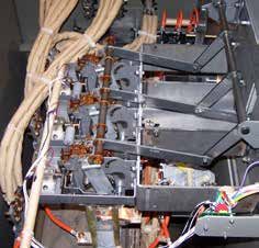
Catalog Data CA202001EN                                                                              Substation transformers-unit and open types
Effective January 2018

 Table 4. Audible Sound Levels
                                   NEMA® Average
 Self-Cooled, Two
 Winding kVA Rating                dB, KNAN                          dB, KNAF

 500                               56                                N/A
 501-700                           57                                67
 701-1000                          58                                67
 1001-1500                         60                                67
 1501-2000                         61                                67
 2001-2500                         62                                67
 2501-3000                         63                                67
 3001-4000                         64                                67
 4001-5000                         65                                67
 5001-6000                         66                                68
 6001-7500                         67                                69
 7501-10000                        68                                70
 10001-12500                       69                                71

 Table 5. Insulation Test Levels
                                                    kV BIL
                            Induced Test                                                Applied
                            180 or 400 Hz                                               Test
 kV Class                   7200 Cycle              Distribution          Power         60 Hz (kV)

 1.2                                                30                    45            10
 2.5                                                45                    60            15
 5                                                  60                    75            19
 8.7                                                75                    95            26
 15                         TWICE                   95                    110           34
                            RATED
 25 (Grd Y Only)            VOLTAGE                 125                   150           40
 25                                                 150                   150           50
 34.5 (Grd Y Only)                                  150                   200           50
 34.5                                               200                   200           70
 46                                                 250                   250           95

 Table 6. Temperature Rise Ratings 0-3300 feet (0-1000 meters)
                                                          Standard              Optional
 Unit Rating                                              65 ºC                 55 ºC, 55/65 °C
 Maximum Ambient Temperature Rise                         40 ºC                 50 ºC
 Ambient Temperature 24 Hour Av.                          30 ºC                 40 ºC
 Temperature Rise Winding¹                                65 ºC                 55 ºC
 Temperature Rise Hotspot                                 80 ºC                 65 ºC
¹ Average Rise by resistance. Refer to IEEE Std C57.12.00™-2010 standard.

NNote: D
        erate kVA by 0.4% for each 100 M (330 ft.) that the altitude is above
       1000 M (3300 ft.).

4                      www.eaton.com/cooperpowerseries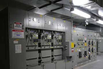
Substation transformers-unit and open types Catalog Data CA202001EN
Effective January 2018
Table 7. Fluid-Filled—Aluminum Windings 55/65 °C Rise1
Drawing Dimensions
(in.) Approx. Total
Gallons Weight (lbs.)
kVA A B C D E F G H J Of Fluid (With Fluid)
500 66 55 26 52 45 45 32 64 35 320 5800
750 75 59 30 60 55 55 34 68 35 370 7200
1000 75 67 30 60 55 55 38 76 35 440 8700
1500 75 67 59 80 55 55 38 76 35 480 10100
2000 85 71 67 90 55 55 40 80 39 550 12600
2500 85 75 68 92 55 55 42 84 41 570 15300
3750 85 75 70 120 65 65 42 84 45 790 20500
5000 99 87 72 144 65 65 48 96 49 1050 26000
7500 99 95 74 148 75 75 52 104 53 1320 35000
10,000 99 103 76 152 75 75 56 112 57 1740 43000
12,000 99 103 82 164 75 75 56 112 61 1850 49000
1 Weights, gallons of fluid, and dimensions are for reference only and not for construction. Please contact your Eaton representative for exact dimensions.
Dimensions for 2500 kVA and below are based on DOE 2016 efficiency requirements
Table 8. Fluid-Filled—Copper Windings 55/65 °C Rise1
Drawing Dimensions
(in.) Approx. Total
Gallons Weight (lbs.)
kVA A B C D E F G H J Of Fluid (With Fluid)
500 66 51 26 52 45 45 30 60 35 310 6100
750 75 59 26 52 55 55 34 68 35 370 7700
1000 75 67 26 52 55 55 38 76 35 430 9200
1500 75 61 59 80 55 55 H 36 72 35 470 10700
2000 85 67 67 90 55 55 38 G 76 39 540 13600
2500 85 73 68 92 55 55 40 80 41 630 15700
3750 85 75 70 120 65 65 42 84 45 830 21500
C
5000 99 87 72 144 65 65 48 96 49 1090 28000
7500 99 95 74 148 75 H3
75 52 104 53 1360 37000
X3 D
10,000 99 103 76 152 75 75 56 X2 112 57 1780 45000
H2
X1
12,000 99 103 82 164 75 H1 75 56 X0 112 61 1880 50000
1 Weights, gallons of fluid, and dimensions are for reference only and not for construction. Please contact your Eaton representative for exact dimensions.
Dimensions for 2500 kVA and below are based on DOE 2016 efficiency requirements
H
G
8
C 3
A
H3 X3 D
E F
H2
X2
X1
2 4
H1 X0
1
B
J base depth
Top View Elevation
Figure 2. High-Voltage left (Segment 2) shown. High-Voltage right (Segment 4) also Figure 3. ANSI® segment designation.
available. 8
www.eaton.com/cooperpowerseries 5
A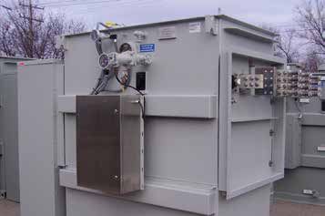
Catalog Data CA202001EN                                                                                          Substation transformers-unit and open types
Effective January 2018

                                                                38"                                                                                              38"
                                                                34"                      2" (Typ.)                                                                34"                      2" (TYP.)

                                         9"         BUSHINGS               8"                                                           10.5"      BUSHINGS                  8"
                                  18"                                                         20"
                                                      CL                                16"                                                           CL
                                         9"                                                                                             10.5"

                                                                                                                                                                                           40"
               4"*        Ø 0.50"                   9"     9"         9"    9"                                                    42" 10.5"                                                      44"
                          12 HOLES

Figure 4. Throat.                                                                                                                       10.5"

* Increase to 5" for containment pans.
                                                                                                                     4"*        Ø 0.50"               9"     9"         9"        9"
                                                                                                                                16 HOLES                          36"

                                                                                                     Figure 7. Flange.
                                                                                38.3"
                                                                                                     *Increase to 5" for containment pans.

                                          10"
 BUSHING
      CL
                                                                                                                                                                                   38.3"
                                                         34"
                                          24"
                                                                                                                                             24"

                                                                                                                                                           34"
                           18"                                         FRONT VIEW                     BUSHING
                                                                 (with Lift-Off Front Panel)               CL
                          22"                                                                                                                10"

                                                                                                                                                                        FRONT VIEW
Figure 5. Air terminal chamber-bottom entry.                                                                                   18"
                                                                                                                                                                  (with Lift-Off Front Panel)
                                                                                                                              22"

                                                                                                     Figure 8. Air terminal chamber-top entry.

                                                                           38.3"

                                              10"                                                                                                                                 38.3"
 BUSHING
      CL

                                                                                                                                                24 "

                                                                                                         BUSHING
                                                                                                              CL
                                              55"

                                                                                                                                                55"

                                                                      FRONT VIEW
                            18"                                 (with Lift-Off Front Panel)
                          22"

Figure 6. Full length cabinet-bottom entry.
                                                                                                                                  18"                                   FRONT VIEW
                                                                                                                                 22"                              (with Lift-Off Front Panel)

                                                                                                     Figure 9. Full length cabinet-top entry.

6                      www.eaton.com/cooperpowerseries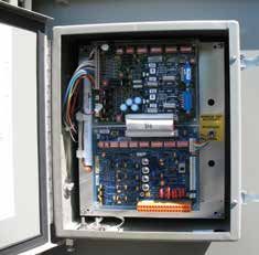
Substation transformers-unit and open types                                                                     Catalog Data CA202001EN
                                                                                                                              Effective January 2018

Standard features
Fluid
•   Envirotemp™ FR3™ fluid
•   Electrical grade mineral insulating oil
Mechanical features
•   De-energized tap changer, externally operable
High- and low-voltage bushings
•   Cover or sidewall-mounted high-voltage porcelain bushings
    • Deadfront bushings also available

•   Cover or sidewall-mounted low-voltage molded epoxy or porcelain        Figure 10. Automation solutions for remote monitoring.
    bushings with NEMA® spades
Tank
•   Tank bases designed for skidding or rolling in any direction
•   Extra-heavy, welded-in-place lifting lugs (4) and jacking provisions
•   Stainless steel grounding pads (4)
•   Cooling radiators or corrugate welded directly to the tank
Gauges and devices
•   Dial-type thermometer
•   Dial-type liquid level gauge
•   Pressure vacuum gauge
•   Cover-mounted automatic pressure relief device
•   Pressure test connection
                                                                           Figure 11. 12-pulse application with bushing supports.
Valves/plugs
•   1” upper fill plug with filter press connection
•   1” upper filter valve (over 2500 kVA)                                  Valves/plugs
•   1” drain valve with sampler combination (2500 kVA and below)           •   Pressure vacuum bleeder valve
•   2” drain valve with sampler (over 2500 kVA)                            •   Detachable, bolt-on radiators with valves
Coatings (Paint)                                                           Control boxes
•   ANSI® #61 Light Gray                                                   •   Control box (NEMA® 4, NEMA® 4X, NEMA® 7)
•   ANSI® #70 Sky Gray                                                     Forced-air fan control package
•   Special paint available per request                                    •   Forced-air fan control package includes fans, NEMA® control box,
Nameplate                                                                      fan controls, dial-type thermometer with alarm contacts

•   Laser-scribed anodized aluminum nameplate                              Overcurrent protection
                                                                           •   Vacuum Fault Interrupter (VFI)
Optional features                                                              •   Visible Break Switch
Bushing enclosure options                                                      •   Tri-phase with Ground Trip technology (TPG)
•   Throat                                                                     •   SCADA
•   Flange                                                                     •   Relays
•   Top- or bottom-entry air terminal chamber                                  •   Feeder Protection Relay (iDP-210)
•   Top- or bottom-entry full length cabinet                                   •   Transformer Protection Relay (iXP-420)
Gauges and devices                                                             •   Motor Operator
•   With Alarm Contacts                                                    •   Bay-O-Net Fuse with Isolation Link
    • Dial-type thermometer (Standard with Fan Package)                    •   Bay-O-Net Fuse with Partial Range Current Limiting Fuse
    •   Liquid level gauge                                                 •   Primary air disconnect switch with fuses
    •   Pressure/vacuum gauge                                              Overvoltage protection
    •   Cover-mounted pressure relief device                               •   Distribution-, Intermediate-, or Station-class surge arresters
    •   Winding temperature indicator                                      •   Elbow arresters (for dead-front connections)
•   Rapid pressure rise relay with optional seal-in panel                  Tank
•   Nitrogen gas preservation system                                       •   304L stainless steel
•   Infrared (IR) Windows

                                                                                                      www.eaton.com/cooperpowerseries             7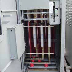
Catalog Data CA202001EN                                                       Substation transformers-unit and open types
Effective January 2018

Overcurrent protection features

Vacuum fault interrupter (VFI) and load interrupter switch (LIS)

Figure 12. VFI—inside transformer tank.          Figure 15. Visible break switch moveable   Figure 18. LIS—switch position viewing
                                                 blades shown in the "Open" position.       window.

Figure 13. VFI—operating handle.                 Figure 16. TPG control with SCADA          Figure 19. LIS—interior view showing
                                                 shown.                                     power fuses.

Figure 14. Motor-operator for open/close         Figure 17. iDP/iXP relays—without and
of vacuum fault interrupter (VFI).               with trip/close pushbuttons.

8              www.eaton.com/cooperpowerseries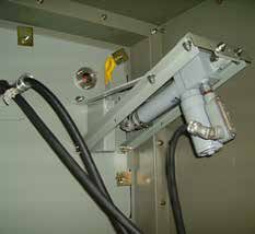
Substation transformers-unit and open types                                                                 Catalog Data CA202001EN
                                                                                                                         Effective January 2018

Construction                                                            Tanks
Core                                                                    Transformer tanks are designed for high strength and ease of
                                                                        handling, installation, and maintenance. Tanks are welded using
The three-legged, step-lap mitered core construction is manufac-        precision-cut, hot rolled, pickled and oiled steel. They are sealed to
tured using a high-quality cutting machine. For maximum efficiency,     protect the insulating fluid and other internal components.
cores are precisely stacked, virtually eliminating gaps in the corner
joints.                                                                 Transformer tanks are design tested to withstand 7 psig without
                                                                        permanent distortion and 15 psig without rupture.
Five-legged wound core or shell-type triplex designs are used for
wye-wye connected transformers, and other special transformer           Tank finish
designs.                                                                An advanced multi-stage finishing process exceeds IEEE Std
Cores are manufactured with precision cut, burr-free, grain-oriented    C57.12.28™-2014 standard. The eight-stage pre-treatment process
silicon steel. Many grades of core steel are available for optimizing   assures coating adhesion and retards corrosion. It converts tank
core loss efficiency.                                                   surfaces to a nonmetallic, water insoluble iron phosphate coating.
Coils                                                                   The paint method consists of three distinct layers of paint. The first
                                                                        is an epoxy primer (E-coat) layer which provides a barrier against
Substation transformers feature a rectangular coil configuration with   moisture, salt and corrosives. The two-component urethane final
wire-wound, high-voltage primaries and sheet-wound secondaries.         coat seals and adds ultraviolet protection.
The design minimizes axial stress developed by short circuits and
provides for magnetic balancing of tap connections.                     Vacuum processing
Coils are wound using the highest quality winding machines              Transformers are dried and filled with filtered insulating fluid under
providing exacting tension control and conductor placement for          vacuum, while secondary windings are energized. Coils are heated
superior short-circuit strength and maximum efficiency.                 to drive out moisture, ensuring maximum penetration of fluid into
                                                                        the coil insulation system.
Extra mechanical strength is provided by diamond pattern, epoxy
coated paper insulation, used throughout the coil, with additional      Cooling system
epoxy at heavy stress points. The diamond pattern distribution of the   Less flammable fluid filled-Air cooling (KNAN) is provided with
epoxy and carefully arranged ducts, provide a network of passages       transformers rated 500 kVA. A choice of KNAN/ Future KNAF (Future
through which cooling fluid can freely circulate.                       Forced-Air) or KNAN/KNAF (Forced-Air) cooling is provided with units
Coil assemblies are heat-cured under calculated hydraulic pressure      rated 750 kVA and above.
to ensure performance against short-circuit forces.                     Insulating fluid
Core and coil assemblies                                                Eaton offers Envirotemp™ FR3™ fluid or electrical grade mineral
Substation transformer core and coil assemblies are braced with         insulating oil in its Cooper Power series transformers. The highly
heavy steel ends to prevent the rectangular coil from distorting        refined fluids are tested and degassed to assure a chemically inert
under fault conditions. Plates are clamped in place using presses,      product with minimal acid ions. Special additives minimize oxygen
and welded or bolted to form a solid core and coil assembly.            absorption and inhibit oxidation. To ensure high dielectric strength,
Core and coil assemblies exceed ANSI® and IEEE® requirements            the fluid is re-tested for dryness and dielectric strength, refiltered,
for short-circuit performance. Due to the rigidity of the design,       heated, dried, and stored under vacuum before being added to the
impedance shift after short-circuit is comparable to that of circular   completed transformer.
wound assemblies.                                                       Transformers filled with Envirotemp™ FR3™ fluid enjoy unique fire
                                                                        safety, environmental, electrical, and chemical advantages, including
                                                                        insulation life extending properties.
                                                                        A bio-based, sustainable, natural ester dielectric coolant,
                                                                        Envirotemp™ FR3™ fluid quickly and thoroughly biodegrades in
                                                                        the environment and is non-toxic per acute aquatic and oral toxicity
                                                                        tests.
                                                                        Building for Environmental and Economic Sustainability (BEES)
                                                                        total life cycle assessment software, utilized by the US Dept. of
                                                                        Commerce, reports its overall environmental performance impact
                                                                        score at 1/4th that reported for mineral oil. Envirotemp™ FR3™ fluid
                                                                        has also earned the EPA Environmental Technology Verification of
                                                                        transformer materials.
                                                                        With a fire point of 360 °C, Envirotemp™ FR3™ fluid is FM
                                                                        Approved® and Underwriters Laboratories® Classified “Less-
                                                                        Flammable” per NEC® Article 450-23, fitting the definition of a Listed
                                                                        Product per NEC®.

                                                                                                 www.eaton.com/cooperpowerseries                  9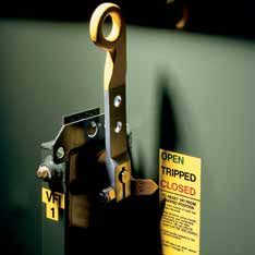
Catalog Data CA202001EN                                                         Substation transformers-unit and open types
Effective January 2018

Substation VFI transformer                                               Specialty designs
Eaton combines a conventional distribution transformer from its          Hardened data center
Cooper Power series transformers with the proven vacuum fault
interrupter (VFI) to offer the VFI transformer. This combination         Envirotran Hardened Data Center (HDC) transformers are designed
provides both voltage transformation and transformer over current        for critical Data Center power delivery where the absolute highest
protection in one space saving and money saving package. The             reliability is required and where mere "Industry Standard" isn't good
substation VFI transformer protects the transformer and provides         enough! Envirotran HDC liquid filled transformers are engineered
proper coordination with upstream protective devices. When a             with higher electrical withstand, increased levels of insulation, and
transformer fault or overload condition occurs, the VFI breaker trips    greater electrical clearance. All Envirotran HDC transformers are
and isolates the transformer.                                            subjected to a more stringent series of factory tests which include
                                                                         a higher BIL withstand than standards dictate for its kV rating and
The three-phase VFI breaker has independent single-phase initiation,     special assurance tests for sealing integrity. Furthermore, Envirotran
but is three-phase mechanically gang-tripped. A trip signal on any       HDC transformers are provided with biobased Envirotemp™ FR3™
phase will open all three phases. This feature eliminates single-        fluid that carries Factory Mutual rated fire resistance, provides
phasing of three-phase loads. It also enables the VFI breaker to be      extended insulation life, and ultimate biodegradability. All of these
used as a three-phase load break switch.                                 characteristics far surpass those of more traditional dry type
Thanks to the resettable characteristics of the VFI breaker, restoring   transformers. Rest assured, Envirotran HDC will deliver the highest
three-phase service is quick and simple.                                 standard of reliability, quality, and performance available in the
The sealed visible break window and switch is an option that can         industry today. See Bulletin B210-10035, Data Center Solutions for
be installed to provide visible break contact. This feature provides     details.
enhanced safety and allows an operator to see if the contacts            Grounding transformers
are in an open or closed position on the VFI before performing
maintenance.                                                             Eaton offers customized grounding transformers for applications
                                                                         where a ground path needs to be introduced to a system.
Envirotran™ FM Approved® transformer
                                                                         Hazardous locations (Class I Division 2)
Eaton's Cooper Power series Envirotran™ transformer is FM
Approved® and suitable for indoor locations. FM Global® approval         Hazardous locations can be defined as areas where combustible
of the Envirotran transformer line makes it easy to comply and           materials are present. Eaton is offering UL® Listed explosion
verify compliance with Section 450.23, 2014 NEC®, Less-Flammable         proof designs that prevent gasses from coming in contact with
Liquid-Filled Transformer Requirements for both indoor and outdoor       switching arcs. These explosion proof control boxes are made of cast
locations.                                                               aluminum and are designed to contain an arc.

FM Approved® Envirotran transformers offer the user the benefit of       Underwriters Laboratories® (UL®) Listed & Labeled/
a transformer that can be easily specified to comply with NEC® and       Classified
makes FM Global® Property Loss Prevention Data Sheet compliance          Eaton's Cooper Power series Envirotran transformer can be specified
simpler, while also providing maximum safety and flexibility for both    as UL® Listed & Labeled and/or UL® Classified.
indoor and outdoor installations.
                                                                         Underwriters Laboratories (UL®) listing is a verification of the
Since the “FM Approved®” logo is readily visible on the transformer      design and construction of the transformer to the ANSI® and IEEE®
and its nameplate, NEC® compliance is now easily verifiable by the       standards. UL® listing generally is the most efficient, cost-effective
inspector.                                                               solution for complying with relevant state and local electrical codes.
Substation Envirotran FM Approved® transformers, part of Eaton's         UL® Combination Classification/Listing is another way in which
Cooper Power series transformers, are manufactured under                 to comply with Section 450.23, 2014 NEC® requirements. This
strict compliance with FM Standard 3990 and are filled with FM           combines the UL® listed transformer with a UL® Classified Less-
Approved® Envirotemp™ FR3™ fluid, a fire-resistant dielectric            Flammable Liquid and complies with the use restrictions found
coolant.                                                                 within the liquid Classification.
ABS® type approved substation transformers                               K-factor
Eaton's Cooper Power series transformers offer liquid-filled             Eaton can design transformers with appropriate K-factor correction
substation and padmounted distribution-class transformers from           to mitigate the effects of non-linear harmonic loading conditions.
0.5 to 10 MVA with type-approved certification from the American
Bureau of Shipping (ABS®) for marine and off-shore applications.         Solar/wind designs
Multi-tap transformers                                                   Eaton is offering custom designs for renewable energy power
                                                                         generation. Eaton's manufactures its Cooper Power series Generator
Our multi-tap transformers step-up the low voltage output from           Step-Up (GSU) transformers for use at the base of each wind
a Variable Speed Drive (VSD) to power your electric submersible          turbine. Additionally, grounding transformers are available for wind
pumps (ESP). With 25 different voltage settings in both delta and        power generation. For the solar photovoltaic industry, Eaton is
wye connections, our transformers can meet a wide variety of pump        offering inverter step-up transformers, as well as dual secondary
applications. Multi-tap transformers are available with both mineral     designs to isolate a two-inverter input.
oil and Envirotemp™ FR3™ fluid and can be specified as UL® Listed
& Labeled. See Product Aid PA202001EN, Multi-tap Transformers for
details.

10              www.eaton.com/cooperpowerseries
Substation transformers-unit and open types Catalog Data CA202001EN
Effective January 2018
Special protection features Testing
Vacuum fault interrupter (VFI) Eaton performs routine testing on each transformer manufactured
including the following tests:
• Provides resettable over current protection using reliable vacuum
bottle interrupters • Ratio, Polarity, and Phase Relation: Ensures correct winding ratios
and tap voltages; checks insulation of HV and LV circuits. Checks
• Utilizes Tri-Phase electronic controller which allows tripping of all entire insulation system to verify all live-to-ground clearances.
three phases upon sensing a fault condition
• Winding Resistance: This test verifies the integrity of internal
• Eaton offers intelligent solutions for enhancing the capabilities of high-voltage and low-voltage connections; provides data for loss
the Tri-phase controller upgrade calculations.
• Tri-Phase with Ground TripTechnology (TPG): • Insulation Power Factor: This test verifies that vacuum processing
has thoroughly dried the insulation system to required limits.
Incorporates separate zero sequence circuit and settings for
special applications where increased sensitivity and speed is • Routine Impulse Tests: The most severe test, simulating a
required in detecting ground fault and phase loading imbalance lightning surge. Applies one reduced wave and one full wave to
conditions. Package includes standard Tri-Phase control features verify the BIL rating.
with an option for SCADA. • Applied Potential: Applied to both high-voltage and low-voltage
• Relays windings, this test stresses the entire insulation system to verify
all live-to-ground clearances.
• iDP-210 relay: Full featured, multi-function programmable relay
includes Phase currents and Event Recorder data and trip • Induced Potential: This test verifies the turn-to-turn and layer-to-
signal to LV Circuit breaker (by others) layer insulation at twice the rated voltage.
• XP-420 relay: Provides all the protection features of iDP-210 • Loss Test: These design verification tests are conducted to ensure
relay with the addition of ANSI® Device#87 that guaranteed loss values are met and that test values are
within design tolerances. Tests include no-load loss and excitation
Primary air disconnect switch current along with impedance voltage and load loss.
• Provides economical, visible disconnect primary load break • Leak Test: Pressurizing the tank to 5 psig assures a complete
switching seal, with no weld or gasket leaks, to eliminate the possibility of
• Fully coordinated and packaged with the transformer moisture infiltration or oil oxidation.
• Meets IEEE Std C37.20.3™-2013 standard, NEMA® SG-5 and Design performance tests
related standards Design performance tests include the following:
• Standard features • Temperature Rise: Our automated heat run facility ensures that any
• Switch design changes meet ANSI® and IEEE® temperature rise criteria.
• Three-pole, two-position, gang-operated air interrupter, • Audible Sound Level: Ensures compliance with NEMA®
unfused requirements.
• Standard ratings • Lightning Impulse: To assure superior dielectric performance,
• 600 A continuous and load break; 40 kA fault close and
this test consists of one reduced wave, two chopped waves and
momentary one full wave in sequence across the medium voltage windings,
precisely simulating the harshest conditions.
• 5 kV (60 kV BIL) or 15 kV (95 kV BIL)
Optional tests
• Enclosure
The following tests are available for purchase:
• Standardized modular self supporting, bolted design
• Zero sequence impedance
• Mechanical safety interlock prevents access when switch is
closed or closing of switch when door is open • RIV (Corona)
• Optional Features • Extended leak test
• 1200 A continuous and load break current rating; 61 kA fault • Dissolved gas analysis (DGA)
close and momentary. Requires 1200 A copper bus option. • PCB fluid testing
• Key interlocks (single cylinder) for interlocking primary switch • Fluid dielectric strength
with secondary main circuit protective device
• Detection of sulfur dioxide
• Auxiliary switch for remote indication of primary switch position
• Where high interrupting ratings and short-circuit protection are Thomas A Edison Technical Center
desired: current-limiting non-expulsion power fuses
We are constantly striving to introduce new innovations to the
• Where lower interrupting ratings are adequate: transformer industry, bringing you the highest quality transformer for
• Non-disconnect power fuses the lowest cost. Eaton's Cooper Power series Transformer Products
are ISO 9001 compliant, emphasizing process improvement in all
• Disconnect power fuses phases of design, manufacture, and testing. We have invested
millions of dollars in the Thomas A. Edison Technical Center, our
premier research facility in Franksville, Wisconsin affirming our
dedication to introducing new innovations and technologies to the
transformer industry. This research facility is fully available for use by
our customers to utilize our advanced electrical and chemical testing
labs.
www.eaton.com/cooperpowerseries 11Catalog Data CA202001EN Substation transformers-unit and open types
Effective January 2018
Figure 20. Substation transformer with visible break Figure 22. Triplex Indoor Power Center comprised of energy
technology. efficient and low noise single-phase substation transformers in
a ganged setup.
Figure 21. Substation transformer with customer-specific Figure 23. Class I Div 2 hazardous duty substation transformer.
coordination and accessories.
Eaton
1000 Eaton Boulevard
Cleveland, OH 44122
United States
Eaton.com
Eaton’s Power Systems Division
2300 Badger Drive
Waukesha, WI 53188
United States
Eaton.com/cooperpowerseries
© 2018 Eaton
All Rights Reserved
Printed in USA Eaton is a registered trademark. For Eaton’s Cooper Power series
Publication No. CA202001EN / substation transformer product
CSSC-1801-5121 All other trademarks are property information call 1-877-277-4636 or
January 2018 of their respective owners. visit: www.eaton.com./cooperpowerseriesYou can also read