Autonomous Navigation for Quadrupedal Robots with Optimized Jumping through Constrained Obstacles - arXiv
←
→
Page content transcription
If your browser does not render page correctly, please read the page content below
Autonomous Navigation for Quadrupedal Robots with Optimized
Jumping through Constrained Obstacles
Scott Gilroy*, Derek Lau*, Lizhi Yang*, Ed Izaguirre, Kristen Biermayer, Anxing Xiao, Mengti Sun,
Ayush Agrawal, Jun Zeng, Zhongyu Li, Koushil Sreenath
Abstract— Quadrupeds are strong candidates for navigating
challenging environments because of their agile and dynamic
designs. This paper presents a methodology that extends the
range of exploration for quadrupedal robots by creating an end-
to-end navigation framework that exploits walking and jumping
arXiv:2107.00773v1 [cs.RO] 1 Jul 2021
modes. To obtain a dynamic jumping maneuver while avoiding
obstacles, dynamically-feasible trajectories are optimized offline
through collocation-based optimization where safety constraints
are imposed. Such optimization schematic allows the robot to
jump through window-shaped obstacles by considering both
obstacles in the air and on the ground. The resulted jumping
mode is utilized in an autonomous navigation pipeline that
leverages a search-based global planner and a local planner
to enable the robot to reach the goal location by walking.
A state machine together with a decision making strategy
allows the system to switch behaviors between walking around
obstacles or jumping through them. The proposed framework
is experimentally deployed and validated on a quadrupedal
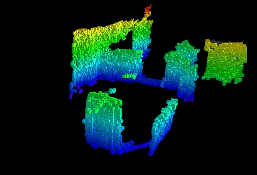
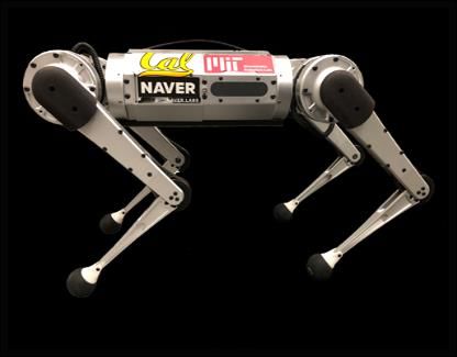
robot, a Mini Cheetah, to enable the robot to autonomously Fig. 1: A Mini Cheetah travelling in a congested environment
navigate through an environment while avoiding obstacles and autonomously by navigating around obstacles and jumping
jumping over a maximum height of 13 cm to pass through a through an obstacle in order to reach the goal location.
window-shaped opening in order to reach its goal. (Video1 )
I. I NTRODUCTION
are obstacles on the ground, the sides and in the air, as shown
Quadrupedal robots have a wide range of mobility modes
in Fig. 1. By solving such a problem, we seek to develop
that allow for greater applicability in navigating challenging
a navigation framework for quadrupedal robots with multi-
environments. Unlike wheeled robots that have difficulty
modal transitions that include walking modes to move around
in traversing uneven terrain, quadrupeds display the ability
obstacles and jumping maneuvers to hop over obstacles in
to adapt to rough terrain [1], [2], and achieve dynamic
order to reach a specified goal location.
motions, such as bounding over obstacles [3], depicting
potentials of usability in unstructured environments and of A. Related Work
being dynamic service robots [4]. Recently, research has
Prior work has demonstrated that quadrupeds have a
shown that quadrupeds are capable of performing a wide
promising ability to move freely through an environment.
range of jumps [5], [6], allowing these robots to reach areas
One approach for motion planning utilizes inverse kinemat-
that were previously inaccessible due to the discrete change
ics, where collision-free trajectories are generated by solving
of ground level. While prior work has demonstrated the
for body poses and foot contact positions [8], [9]. While this
feasibility of jumping maneuvers on quadrupedal robots [7],
method was presented to solve for trajectories quickly, the
the additional constraints of jumping through constrained
use of inverse kinematics cannot prevent singularities from
obstacles, i.e., jumping while avoiding a collision, was
occurring. Singularities could easily present when moving
not considered. Moreover, autonomous navigation exploiting
legs to avoid height-constrained environments. Alternatively,
the jumping ability to avoid obstacles of these robots in
jumps can be accomplished by scaling the impulse applied
congested environments has not been demonstrated. In this
during bounding to complete running jumps as seen in [10].
paper, we focus on tackling a challenging scenario where the
However, this work fails to consider window-shaped obsta-
traversable region is narrow and window-shaped, i.e., there
cles. Trajectory optimization has been utilized to generate
* Authors have contributed equally. jumps in [3] but lacks the integration with navigating through
1 Experimental videos can be found at https://youtu.be/ unknown environments.
5pzJ8U7YyGc. Motion planning for agile movements such as jumping can
All authors are affiliated with UC Berkeley, USA. {scott_gilroy,
delau, lzyang, eizaguir, kbiermayer, xax, also be formulated as an optimization problem, where the
mengtisun, ayush.agrawal, zengjunsjtu, dynamics of the robot as well as obstacles are incorporated in
zhongyu_li, koushils}@berkeley.edu the constraints to obtain optimal state trajectories [11], [12],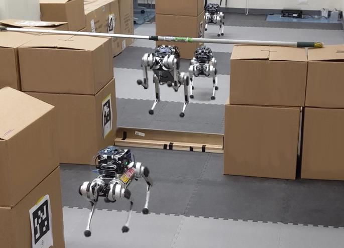
Goal Location Reference
 Next Jumping Trajectory trajectory
 Global Planner, Controllers, Sec. VI
 waypoint Optimization, Sec. IV
 Sec. V Motor
 Jumping Controller torque
 Decision Making, Velocity Commands
 Obstacles
 Sec. V
 Local Planner, Sensor
 Vision-Based Walking Controller data
 Mapping, Sec. V Sec. V

Fig. 2: Proposed framework for navigating in confined spaces with an optimized jumping mode. This autonomous pipeline
allows the robot to sense the environment with an RGB-Depth camera and a tracking camera. A global path to reach the
goal location is obtained by a search-based planner. A state machine determines robot locomotion modes, such as walking
and jumping, in order to move around or jump over obstacles that are not traversable by walking.

[5]. Robots such as SALTO-1P [13], the MIT Cheetah [10], environments that are previously nontraversable by only the
[3], and ANYmal [14] have all displayed capabilities in walking mode.
performing jumps and navigating around the environment.
A common approach in such techniques is to use a reduced
 II. F RAMEWORK
order model of the robot by binding the left and right legs to
improve computation speed while not sacrificing the ability The proposed navigation autonomy using quadrupedal
to jump along the sagittal plane [6], [7]. Various control tech- robots developed in this paper is illustrated in Fig. 2. The
niques such as Model Predictive Control (MPC) [15], Whole- environment is perceived by an RGB-Depth camera, and ob-
Body Impulse Control (WBIC) [2], [16] or PD control [6], stacles are registered into maps which include the maximum
[7] can then be used to track these reference trajectories. obstacle height on each grid. After being given a target goal
These works, however, do not consider jumping in highly location, a global planner using A* [20] is constructed to find
constrained environments such as jumping through window- a sequence of collision-free waypoints on the map from the
shaped obstacles. robot’s current position to the goal location. A state machine
 Our approach leverages recent results in trajectory opti- is designed to switch between the robot locomotion modes
mization using a duality-based approach [17] which allows of walking and jumping. A local planner is later developed
us to convert obstacle avoidance criteria between two con- to obtain desired walking velocity profiles for the robot
vex regions, i.e., maintaining a minimum distance, into a to track a waypoint selected from the global path. If the
differentiable and smooth non-convex avoidance constraint. planned waypoints cross a non-traversable obstacle which
The smoothness property allows the use of general-purpose the robot is capable of jumping over, the state machine will
gradient- and Hessian-based optimization algorithms in tra- prepare the robot to jump. Mapping, planners, and the state
jectory generation. This approach has been applied to differ- machine use Visual Intertial Odometry (VIO) to estimate
ent robots, such as quadrotors [18] and wheeled robots [19]. the robot’s current state and they are introduced in Sec. V.
This motivates us to apply this formulation of obstacle In order to enable the robot to attain a dynamic jumping
avoidance to the legged systems, which could be exploited to mode while considering the surrounding confined space,
generate a collision-free trajectory through height-constraint such as a window-shaped obstacle, trajectory optimization
obstacles. is formulated offline to obtain dynamically-feasible joint
B. Contributions profiles for the robot while imposing collision-avoidance
 The main contributions of this paper are the development constraints. This optimization is discussed in Sec. IV and
of one of the first end-to-end navigation autonomy for it is based on the robot planar model presented in Sec. III.
quadrupedal robots to travel in an unstructured environment A jumping controller developed in Sec. VI empowers the
through multi-modal transition. Such framework leverages robot to perform the optimized trajectory, resulting in a safe
two locomotion modes, planar walking and forward jumps. landing on the target point behind the obstacles. Such model-
In order to achieve dynamic jumping maneuvers while avoid- based vision-to-torque navigation pipeline is deployed on
ing obstacles, a multi-phased collocation based nonlinear a Mini Cheetah and is validated in experiments presented
optimization is firstly developed to generate a trajectory of in Sec. VII. Conclusion and future work is discussed in
the robot to jump through window-shaped obstacles while re- Sec. VIII.
specting the robot’s physical limitations. A controller is also
introduced to enable the robot to achieve the optimized jump III. M ODEL AND DYNAMICS
online. By integrating a state machine, path planners, and
the proposed jumping controller into the navigation pipeline, In this section, we characterize the quadrupedal jumping
we firstly enable a quadrupedal robot, the Mini Cheetah, behavior with different phases. According to the jumping
to intelligently choose either walking around obstacles or behavior, the robot is simplified under a planar model and
jumping over obstacles without collision while traveling in the corresponding dynamics is also introduced.
 3
 1

 4 1
 1 2
 2 2
 Fig. 4: Jumping behavior of a simplified quadrupedal robot.
Fig. 3: Simplified planar model used for quadruped jumping. The phases can be distinguished as all feet contact, rear
The planar model consists of base position, orientation feet contact, flight, and landing, respectively. The possible
together with four joints. The inputs of this planar model window-shaped obstacles are colored in red in the flight
are four torques acting on joints. phase.

A. Simplified Model C. Simplified Dynamics
 The jumping behavior of the quadruped motivates us The dynamics of the planar model can be modeled based
to propose a simplified model that takes advantage of the upon the Lagrangian equations of motion [22]:
robot’s symmetry. A planar model with two legs is used D(q)q̈ + C(q, q̇)q̇ + G(q) = Bu + J(q)T T, (4)
to capture the jumping behaviors for the quadruped and is
shown in Fig. 3. The system states x and control inputs u where D(q) is the Mass-Inertia matrix, C(q, q̇) is the
of this simplified model are as follow, Coriolis matrix, G(q) is the gravity vector, B is the in-
 put mapping matrix, u is the joint torques and T :=
 q := [qx , qz , qθ , qF 1 , qF 2 , qB1 , qB2 ]T ∈ R7 (1) [TF x , TF z , TBx , TBz ]T ∈ R4 denotes the contact forces act-
 14 ing on the front and back leg from the ground. Additionally,
 x := [q; q̇] ∈ R (2)
 u := [τF 1 , τF 2 , τB1 , τB2 ]T ∈ R4 , (3) the following constraint is needed for the feet to be in contact
 with the ground.
where qx , qz and qθ represent the robot’s base position and
 J(i) (q)q̈ + J̇(i) (q)q̇ = 0. (5)
pitch angle, respectively. q = [qF 1 , qF 2 , qB1 , qB2 ]T is the
hip and knee joint angles of the front and back leg of the By combining equations (4) and (5), we could capture the
simplified model and u represents the input of this planar system dynamics at i-th phase with notations as follow,
model which consists of torques acting on the front and
back leg. The simplification from the original four-legged ẋ = f (i) (x, u, T) (6)
model [21] allows us to reduce the computational complexity
by reducing from the 18 Degrees-of-Freedom (DOF) model IV. J UMPING T RAJECTORY G ENERATION
for the 3D quadruped into 7 DOF for the planar system. After having introduced the simplified model and dynam-
 We also denote the robot’s pose in 3D by using qy to ics for quadrupedal jumping, we are going to illustrate the
represent the robot’s position in the lateral direction and qφ trajectory generation for jumping mode using a collocation-
to represent the robot’s turning yaw. based optimization. The optimization formulation is intro-
 duced in Sec. IV-A. After that, cost function design, physical
B. Quadrupedal Jumping constraints, and safety constraints are presented in Sec. IV-B,
 The jumping maneuver of quadrupedal robots is featured IV-C, and IV-D, respectively.
as four different phases as illustrated in Fig. 4, which include:
 A. Formulation
all feet contact, rear feet contact, flight, and landing:
 1) All feet contact phase: Both the front and back feet are We propose an optimization-based trajectory generation
 in direct contact with the ground. To transition to the for the jumping motion, which is stated as follows,
 rear feet contact phase, the quadruped pushes off the min J(x, ẋ, u, T) (7a)
 ground using the front legs and rotates upon the back x,ẋ,u,T

 feet. ∆t(i)
 s.t. x(tk+1 ) = x(tk ) + (ẋ(tk+1 ) + ẋ(tk )) (7b)
 2) Rear feet contact phase: The back legs extend allowing 2
 for the quadruped to push off the ground. When the ẋ(tk+1 ) = f (i) (x(tk ), u(tk ), T(tk )) (7c)
 contact forces of the back legs become zero, the robot x(t0 ) = x0 (7d)
 switches into the flight phase.
 (i)
 3) Flight phase: The whole robot is under free fall while where ∆t = Ti /Ni for the i-th phase (as described in
 being able to reconfigure in the air allowing itself to Sec. III-B) with the duration of the phase being Ti and the
 perform different tasks, such as avoiding obstacles. number of collocation nodes in the phase being Ni . The
 4) Landing phase: At the end of the flight phase, the robot optimization
 P(7) optimizes of the cost function J(x, ẋ, u, T)
 4
 remakes contact with the ground on all feet. over N = i=1 Ni collocation nodes. The constraint on the
Obstacle
initial condition x0 is in (7d). The trapezoidal constraints be- Current configuration

tween nodes are in (7b) and system dynamics are considered
as constraints in (7c).
 ( ) Signed distance
B. Cost Function ( ) >
 The cost function J(x, ẋ, u, T) is formulated as follow,
 ℎ( ) Initial configuration
 J =(q(tN +1 ) − q0 )T Pf (q(tN +1 ) − q0 ) ( )
 N +1
 Fig. 5: Obstacle avoidance between quadruped in flight phase
 X
 + (q̇T (tk )Qq̇ q̇(tk ) + q̈T (tk )Qq̈ q̈(tk )
 k=0
 and window-shaped obstacle. The key points of the robot to
 (8) construct bounding box are marked as blue and the center of
 + T(tk )QT T(tk ) + uT (tk )Ru u(tk ))
 the bounding box is marked as red. Safety constraint between
 2 N2
 X X the bounding box and the convex obstacle (colored in red)
 + Pi Ti + Pδ δ
 is maintained by forcing the signed distance d between them
 i=1 i=1
 to be larger than a safety margin dmin .
where Qq̇ , Qq̈ , QT , and Ru represent the positive definite
matrices for stage cost and input cost respectively. q0 is
the configuration of joint angles while standing and the first rectangular bounding-box encapsulating the model through-
term of (8) minimizes the error between
 P2 it and the final joint out the trajectory. We model the bounding-box as a convex
configuration of the optimization. i=1 Pi Ti minimizes the set by utilizing six key points pi (tk ) (the red points in Fig. 5)
travel time for Phases 1 and 2 with Pi being positive scalars. on the robot: two points on hip, knee, and feet, respectively,
Next, δ is the relaxation variable for leg contact
 PN2 during whose coordinates are denoted as pi = [xpi , zpi ]T ∈ R2 .
Phase 2 and it is minimized by the cost term i=1 Pδ δ. All The center of the bounding box pc (tk ) (the purple point in
the costs above together minimizes the joint velocities and Fig. 5) is determined by the mean position of the key points,
acceleration for all states to generate a smoother optimized 6
trajectory with appropriate control inputs. 1X
 pc (tk ) = pi (tk ) (9)
 6 i=1
C. Physical Constraints
 The following constraints are added to the optimization and the rotation Ry (tk ) = Ry,qθ is assumed as the robot
to account for geometric limitations and physical hardware body pitch angle. The controlled bounding box (the solid
limitations: blue rectangle in Fig. 5) could be regarded as a convex region
 E(t) transformed from an initial convex set B(t) with rotation
 • Joint Angle: qmin ≤ q(tk ) ≤ qmax
 Ry (tk ) ∈ R2×2 and translation P(tk ) ∈ R2 at each time
 • Joint Velocity: q̇min ≤ q̇(tk ) ≤ q̇max
 step.
 • Torque: umin ≤ u(tk ) ≤ umax
 TF x (tk ) TBx (tk ) E(tk ) = Ry (tk )B(tk ) + P(tk ). (10)
 • Friction Cone: T (t ) , T (t ) ≤ µ
 Fz k Bz k
 • Contact Force: Tz,min ≤ TBz (tk ), TF z (tk ) ≤ Tz,max Here, P(tk ) = pc (tk ) and the initial bounding box (the
 • Contact Position: −δ ≤ zC ≤ 0 dashed blue rectangle in Fig. 5) could be considered as
Here, the joint position, velocity, and torque limitations are a rectangle centered at origin O with time-varying width
considered under physical hardware constraints [21] and the w(tk ) and height h(tk ), which could be represented as
friction coefficient µ for the contact legs is assumed as B(tk ) = {y : L(w(tk ), h(tk ))y ≤ l} where L ∈ R4×2 .
 To ensure our bounding box is valid, we add an additional
a value of 0.5. The rear feet contact phase is the most
 cost term as follow into (8) to minimize height and width
significant part for the jumping performance, where we
 along the trajectory,
enforce contact force and position constraints. The maximum X
contact force Tz,max is estimated with physical hardware Jw,h (tk ) = w(tk )2 + h(tk )2 , (11)
limitation and a minimum contact force Tz,min is included k
to ensure the optimized force is large enough to support the while enforcing the i-th key points to lie inside the four
weight of the robot. zC represents the vertical position of the vertices Vj (tk ) ∈ R2 (the blue points in Fig. 5) of the
contact point of the back leg on the ground, which should bounding box with the following equality constraints
be zero but it is relaxed with a variable δ to enhance the
 4
feasibility of the local planner. X
 pi (tk ) = Vj (tk )γij (tk ). (12)
D. Safety Constraints for Obstacle Avoidance j=1

 Obstacle avoidance provides an additional constraint for Here, γij (tk ) denotes the weight for j-th vertex under the
the optimization in which a convex set that represents the convex representation of i-th key points at each time step tk .
bounding-box of the robot maintains a minimum distance 4
 X
from convex obstacles [18], [19], shown in Fig. 5. The γij (tk ) = 1, γij (tk ) ≥ 0 (13)
quadruped is modeled as a controlled object E(tk ) with a j=1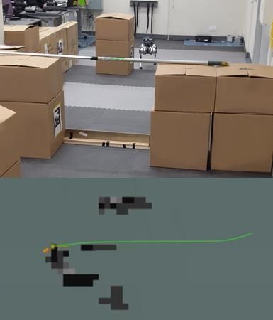
When the robot intends to jump through the obstacle, the Traversable Region
upper and lower boundaries of a window-shaped obstacle are Voxel Grid with Jumps
considered as a combination of two obstacles. Each of them
can be described as a convex set O with a rectangular shape,
 O = {y ∈ R2 : AO y ≤ bO }. (14) Depth
 External Camera
The obstacle avoidance optimization algorithm is equivalent Computer
to a dual optimization problem at each time step tk as External
follows, with the minimum signed distance d being larger Battery
than a safety margin dmin , Tracking
 T T Camera
 −l µ(tk ) + (AO P(tk ) − bO ) λ(tk ) > dmin
 LT µ(tk ) + Ry (tk )T ATO λ(tk ) = 0 (15) 2.5D Map
 ||ATO λ(tk )|| < 1, λ(tk ) > 0, µ(tk ) > 0.
 Fig. 6: The Mini Cheetah carries a sensor suite that contains
Here, λ and µ are dual variables related to the obstacle an RGB-Depth camera, a tracking camera, and an additional
O. The detailed proof of (15) with duality can be found power source and computer for online navigation. The robot
in [17]. The additional cost in (11) together with key points uses the tracking camera to estimate its current state. The 3D
constraints in (12) and obstacle avoidance constraints in (15) environment represented by a voxel grid is perceived by the
allows the robot to change its intrinsic dimensions to jump RGB-Depth camera. A 2.5D map that records the obstacle
through a height-constrained obstacle. height in each grid is updated from the voxel grid. The
 Additionally, the final state constraint is proposed as darkness of the grid grows with increasing obstacle height. A
follow, region that has obstacles whose heights are below the robot’s
 qx (tN +1 ) ≥ xobs , (16) jumps are classified as a traversable region with jumps.
which ensures that the robot lands past the obstacle in its
final configuration, where xobs represents the x position of
the obstacle. This constraint is necessary, otherwise, the local camera (Intel RealSense D435i), and a tracking camera (Intel
planner might generate a safe but conservative trajectory RealSense T265). The additional computer and sensors are
without jumping past the obstacle. used to accurately map and localize the robot while exploring
 the environment.
 V. P LANNERS RTAB-Map is used to generate a 3D point cloud of
 In order to utilize the optimized jumping maneuver to heights in the environment [23]. From the voxel grid with a
travel through a congested space, the jumping mode is resolution of 0.1 m, two maps are created, an occupancy map
embedded into an autonomous navigation framework with with a resolution of 0.1 m and a 2.5D map with a resolution
localization and mapping, motion planners, and a gait deci- of 0.2 m. The maximum height of the voxel grid of the same
sion maker as introduced in this section. planar coordinates is recorded. If this height is above what
 This framework works as follows. Two maps are generated the robot can jump over, this grid is marked as untraversable
and updated in this pipeline. One is a 2D occupancy grid map with a Boolean variable 0, otherwise, the grid will be a free
encoding the traversable region for the robot, and a 2.5D space encoded by Boolean variable 1, and this information is
map keeps track of the obstacle height in the environment. stored in a 2D occupancy map. A coarser 2.5D map is also
A global planner searches for a global path on the occupancy created along with the voxel grid, which features a map of
map and sends an in-range target waypoint to the state discrete tiles sizes, i.e., 0.2 m. The maximum height within
machine. Based on the coordinate of waypoint, the state the tile is then marked as obstacle height z obs in that tile, as
machine decodes the obstacle height from 2.5D height map illustrated in Fig. 6.
and decides whether the robot should use walking or jumping The observed robot current states in the 3D space,
modes. If a change of modes is detected, the state machine [q̃x,y,z,φ , q̇˜x,y,z,φ ]T , are estimated by Visual Inertial Odome-
also adds a standing mode to smooth the mode transitions. try (VIO) through the tracking camera.
Moreover, the state machine also adds desired yaw rotation
 B. Global Planner
based on the selected modes. The target waypoint and desired
yaw position are tracked by a local planner when the walking To find a global path from the current robot position to
mode is chosen. the given goal location, a search-based A* planner over the
 updated 2D occupancy map is utilized to find a collision-
A. Mapping and Localization free path that contains a sequence of 2D coordinates of
 Additional onboard computing and sensors are included waypoints. The global planner also considers an inflation of
to enable the robot to navigate through the environment. A 0.4 m of the occupied grid as a planning safety buffer. In the
sensor suite, as shown in Fig. 6, includes an Intel NUC planned global path, a waypoint that is ahead of the robot’s
providing external computing resource with a RGB-Depth current position coordinate in the given range is selected. In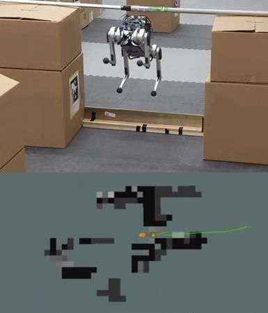
this paper, we choose a waypoint that is 0.3 m ahead of the A. Jumping Control
robot. The 2D coordinate [qxdes , qydes ] and its obstacle height For a robot jump, the trajectory optimization in Sec. IV
z obs are recorded in the 2.5D map and sent to the following solves for a reference trajectory with the desired joint angles
state machine and local planner. qdes ∈ R4×N , joint velocities q̇des ∈ R4×N , and torque
C. State Machine inputs τ des ∈ R4×N . The reference joint trajectory and
 torque input are then linearly interpolated with a 1 kHz
 After receiving a target waypoint with the information of sample rate and are sent to a joint-level PD controller with
admissible height from the global planner, a state machine is a feed-forward term of desired torque, as follow,
developed to choose robot locomotion modes to jump, stand,
or walk. Moreover, the state machine also decides a target τ = τ des + Kp,i (qdes − q) + Kd,i (q̇des − q̇) (17)
yaw position of the waypoint. If the obstacle height is 0 m, 3×3 3×3
 where Kp,i ∈ R and Kd,i ∈ R are proportional and
which indicates that it is a free space that the robot can walk
 derivative gains during the i-th phase and τ des is the feed-
through, the state machine sets the target yaw position as the
 forward torque obtained from the optimization for jumping.
direction between robot current coordinate and waypoint, i.e.,
 Gain scheduling of both Kp,i and Kd,i occur so that the
qφdes =< [q̃x , q̃y ]T , [qxdes , qydes ]T >. If the obstacle height is
 gains for each phase of the jump can be tuned independently.
non-zero, the state machine will proceed to prepare the robot
 During the landing phase, the proportional and derivative
to jump. Firstly, the desired yaw is set to be perpendicular
 gains are interpolated which respect the landing phase’s
to the obstacle to jump over, and the position of the target des des
 duration, i.e., τlanding = λτlanding , where the feed-forward
waypoint will be held and not updated. This will lead the
 torque is decreased by a factor, λ, to reduce the impact
robot to reach to the obstacle and get prepared to jump. Once
 of timing mismatch has when the quadruped re-establishes
the robot arrives at the target coordinate, the state machine
 contact with the ground. By manipulating both the gains and
will firstly switch the robot from the walking mode to a
 feed-forward torque during landing, the quadrupedal robot is
standing mode, and then switch to the jump mode. After the
 more robust to errors in the landing time, where the optimal
robot executes the jump and lands, the state machine will
 landing trajectory is used. By interpolating the gains, the
switch back to walking mode through a standing transition,
 spike of motor torque upon landing will be reduced while
and the target waypoint will be updated by the global planner.
 still allowing the robot to reach the desired end configuration.
Note that the obstacle height from the given waypoint is
 This results in safe landing maneuvers even in the scenarios
always admissible for the robot to jump over as the global
 where the robot’s landing configuration deviates from the
planner will avoid obstacles that are beyond the robot’s jumps
 planned one.
ability in the 2D occupancy map.
 The output from the state machine contains discrete loco- B. Walking Control
motion modes: jumping, standing, and walking, and target A model predictive controller (MPC) and whole body
waypoint with desired yaw qφdes . impulse controller (WBIC) was developed in [16] for the
D. Local Planner for Walking Mini Cheetah. Empowered by this controller, the robot is
 able to track given planar velocity and yaw rotation rate from
 If the state machine decides to use the walking mode of the the local planner developed in Sec. V-D while maintaining
quadrupedal robot to walk around the obstacles, a local plan- gait stability.
ner that is able to track the given waypoint with orientation
[qxdes , qydes , qφdes ]T is designed. This local planner leverages VII. E XPERIMENTS AND E VALUATION
a collocation-based trajectory optimization using a simple Using the approach described throughout this paper, the
double integrator dynamics to track the given waypoint. The performance was evaluated based upon the Mini Cheetah’s
optimization problem with collocation has 30 nodes and ability to navigate through environments, to detect and jump
spans over 1 second. The decision variables include the states over the obstacle, and to continue navigating to the goal
of robot planar and yaw positions and their derivatives. It is location. This approach is validated with experiments using
formulated to minimize the distance between the final node different environments, i.e., obstacle configurations, and is
to the target waypoint while respecting the robot’s actual demonstrated in the supplementary video1 . The environment
velocity limits. The optimized trajectory contains a sequence contains obstacles of various sizes obstructing the path of the
of robot desired walking velocities, q̇xdes , q̇ydes , and turning Mini Cheetah, shown in Fig. 7, and some of them cannot
rates q̇φdes , and will be tracked by the robot using a walking be traversed only by walking. Without having the ability
controller. to jump over certain obstacles, an environment with large
 VI. C ONTROL obstructions would prevent quadrupeds from reaching the
 goal location.
 After having seen trajectory generation and planners for The Mini Cheetah with the carried sensor suite is able
two locomotion modes, we are going to present the con- to detect obstacles and create maps of the environment.
trollers that are used to enable quadrupedal robots to realize While navigating through the environment, the Mini Cheetah
these locomotion behaviors, where jumping and walking
controllers are described in Sec. VI-A and VI-B, respectively. 1 https://youtu.be/5pzJ8U7YyGc
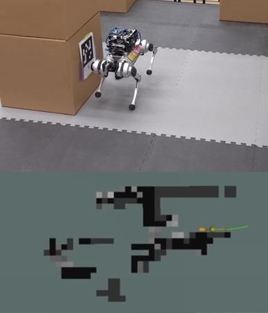
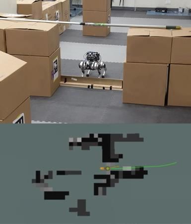
Initial Position

 Goal Location

 Target Waypoint with Global Path
 Desired Yaw

 Goal
 Local Path Location

 (a) (b) (c) (d)
Fig. 7: A snapshot of the Mini Cheetah: (a) avoiding an obstacle within the environment while navigating to the end goal;
(b) preparing to jump over an obstacle that obstructs the robot from the goal; (c) robot in flight jumping through the obstacle;
and (d) continuation of navigating the environment to the end goal. Top-view of the mapped environment in RViz is shown
in the bottom plots. The robot initial position and goal location are marked as red and yellow points, respectively. The global
path is represented by green line while the local path is denoted as yellow points. The target way point with desired yaw
orientation given from the state machine is shown as green point.
 30 20
 Joint Velocity (rad/s)
Joint Position (rad)

 4

 Joint Torque (Nm)
 20
 10
 2
 10
 0
 0
 0

 -2 -10
 -10

 -4 -20 -20
 0 0.5 1 1.5 2 0 0.5 1 1.5 2 0 0.5 1 1.5 2
 Time (s) Time (s) Time (s)

 (a) Front Leg Joint Angles (b) Front Leg Joint Velocities (c) Front Leg Joint Torques
 30 20
 Joint Velocity (rad/s)
Joint Position (rad)

 4
 Joint Torque (Nm)

 20
 10
 2
 10
 0
 0
 0

 -2 -10
 -10

 -4 -20 -20
 0 0.5 1 1.5 2 0 0.5 1 1.5 2 0 0.5 1 1.5 2
 Time (s) Time (s) Time (s)

 (d) Back Leg Joint Angles (e) Back Leg Joint Velocities (f) Back Leg Joint Torques
Fig. 8: The comparison between the measured joint angles, velocities, and torques from the experiment, which are shown
in solid lines, and the desired values from the jumping trajectory optimization drawn in dash lines. The values plotted are
gathered from the hip and knee joints of the front right and back right legs of the robot. The front hip joint is shown as
red, the front knee joint is demonstrated as blue, back hip is drawn as green and the back knee is marked as yellow.

accurately marks higher obstacles and safely walks around tracking of both the joint position and velocity throughout
them, shown in Fig. 7a. Once an obstacle that can be jumped the duration of the jump while obeying the physical hardware
over is found, the Mini Cheetah tunes its orientation to point limitations. In Fig. 8, spikes in joint velocity indicate the
towards the obstacle and navigates in front of it. Afterward, transition between all feet contact and rear feet contact at 0.7
the Mini Cheetah can successfully perform the jumping s in Fig. 8b, transition from rear feet contact to flight at 0.9
maneuver and clear the obstacle. Fig. 7b demonstrates the s in Fig. 8e, and the impact of landing at 1.4 s in Fig. 8b, 8e.
Mini Cheetah overcoming a 13 cm tall obstacle with a In the optimization-based trajectory generation, the landing
window size of 70 cm that would normally not be traversable phase is optimized with a lower coefficient of friction than
by walking. the take off phase to prevent the possibility of over rotation
 Fig. 8 shows the tracking performance of the joint angles of the robot upon landing with a high horizontal velocity. To
and velocity for all four phases of the jump over a 13 cm tall reduce the overall tendency to bounce upon landing, gains
obstacle. The PD controller running at 1 kHz provides great are interpolated throughout the landing phase.
Experiments throughout this paper are nearing the maxi- [6] Q. Nguyen, M. J. Powell, B. Katz, J. D. Carlo, and S. Kim, “Optimized
mum jumping heights due to the hardware limitations of the jumping on the mit cheetah 3 robot,” in 2019 International Conference
 on Robotics and Automation (ICRA), 2019, pp. 7448–7454.
Mini Cheetah. With the current torque to weight ratio of the [7] D. Kim, D. Carballo, J. Di Carlo, B. Katz, G. Bledt, B. Lim, and
Mini Cheetah, the robot is able to clear obstacles up to 13 S. Kim, “Vision aided dynamic exploration of unstructured terrain
 with a small-scale quadruped robot,” in 2020 IEEE International
cm tall with the 2.25 kg sensor suite attached. Additional Conference on Robotics and Automation (ICRA), 2020, pp. 2464–
experimentation is conducted without the sensor suite, and 2470.
the Mini Cheetah is capable of clearing obstacles up to 24 [8] M. Geisert, T. Yates, A. Orgen, P. Fernbach, and I. Havoutis, “Contact
 planning for the anymal quadruped robot using an acyclic reachability-
cm. Both experiments conducted are able to demonstrate that based planner,” in Annual Conference Towards Autonomous Robotic
the optimization problem can solve for optimal trajectories Systems. Springer, 2019, pp. 275–287.
with different torque to weight ratios. Quadrupedal robots [9] R. Buchanan, L. Wellhausen, M. Bjelonic, T. Bandyopadhyay, N. Kot-
 tege, and M. Hutter, “Perceptive whole-body planning for multilegged
with larger torque to weight ratios using the methodology robots in confined spaces,” Journal of Field Robotics, vol. 38, no. 1,
presented in this paper would therefore be capable of clearing pp. 68–84, 2021.
higher obstacles than shown in experiments. [10] H.-W. Park, M. Y. Chuah, and S. Kim, “Quadruped bounding con-
 trol with variable duty cycle via vertical impulse scaling,” in 2014
 VIII. C ONCLUSION AND FUTURE WORKS IEEE/RSJ International Conference on Intelligent Robots and Systems,
 2014, pp. 3245–3252.
 In this paper, we introduced a navigation autonomy for [11] A. W. Winkler, C. D. Bellicoso, M. Hutter, and J. Buchli, “Gait and
quadrupedal robots to maneuver in cluttered environments trajectory optimization for legged systems through phase-based end-
while avoiding obstacles. We developed an end-to-end frame- effector parameterization,” Robotics and Automation Letters, vol. 3,
 no. 3, pp. 1560–1567, 2018.
work that enabled multi-modal transitions between walking [12] M. Neunert, F. Farshidian, A. W. Winkler, and J. Buchli, “Trajec-
and jumping skills. Using multi-phased collocation based tory optimization through contacts and automatic gait discovery for
nonlinear optimization, optimal trajectories were generated quadrupeds,” Robotics and Automation Letters, vol. 2, no. 3, pp. 1502–
 1509, 2017.
for the quadrupedal robot while avoiding obstacles and al- [13] J. K. Yim, B. R. P. Singh, E. K. Wang, R. Featherstone, and R. S.
lowing the robot to jump through window-shaped obstacles. Fearing, “Precision robotic leaping and landing using stance-phase
An integrated state machine, path planner, and jumping and balance,” Robotics and Automation Letters, vol. 5, no. 2, pp. 3422–
 3429, 2020.
walking controllers enabled the Mini-Cheetah to jump over [14] M. Hutter, C. Gehring, A. Lauber, F. Gunther, C. D. Bellicoso,
obstacles and navigate previously nontraversable areas. V. Tsounis, P. Fankhauser, R. Diethelm, S. Bachmann, M. Blösch
 Future work includes implementing an online trajectory et al., “Anymal-toward legged robots for harsh environments,” Ad-
 vanced Robotics, vol. 31, no. 17, pp. 918–931, 2017.
optimization and optimizing for jumps where the take off [15] J. Di Carlo, P. M. Wensing, B. Katz, G. Bledt, and S. Kim, “Dynamic
and landing are not at the same elevation. locomotion in the mit cheetah 3 through convex model-predictive
 control,” in 2018 IEEE/RSJ International Conference on Intelligent
 ACKNOWLEDGMENTS Robots and Systems (IROS), 2018, pp. 1–9.
 [16] D. Kim, J. Di Carlo, B. Katz, G. Bledt, and S. Kim, “Highly dynamic
 This work is supported in part by National Science Foun- quadruped locomotion via whole-body impulse control and model
dation Grants CMMI-1944722. The authors would like to predictive control,” arXiv preprint arXiv:1909.06586, 2019.
thank Professor Sangbae Kim, the MIT Biomimetic Robotics [17] X. Zhang, A. Liniger, and F. Borrelli, “Optimization-based collision
 avoidance,” Transactions on Control Systems Technology, 2020.
Lab, and NAVER LABS for providing the Mini Cheetah [18] J. Zeng, P. Kotaru, M. W. Mueller, and K. Sreenath, “Differential flat-
simulation software and lending the Mini Cheetah for ex- ness based path planning with direct collocation on hybrid modes for a
periments. quadrotor with a cable-suspended payload,” Robotics and Automation
 Letters, vol. 5, no. 2, pp. 3074–3081, 2020.
 R EFERENCES [19] X. Zhang, A. Liniger, A. Sakai, and F. Borrelli, “Autonomous parking
 using optimization-based collision avoidance,” in 2018 IEEE Confer-
 [1] C. Mastalli, I. Havoutis, M. Focchi, D. G. Caldwell, and C. Semini, ence on Decision and Control (CDC), 2018, pp. 4327–4332.
 “Motion planning for quadrupedal locomotion: Coupled planning, [20] P. E. Hart, N. J. Nilsson, and B. Raphael, “A formal basis for
 terrain mapping, and whole-body control,” IEEE Transactions on the heuristic determination of minimum cost paths,” Transactions on
 Robotics, vol. 36, no. 6, pp. 1635–1648, 2020. Systems Science and Cybernetics, vol. 4, no. 2, pp. 100–107, 1968.
 [2] C. Yang, B. Zhang, J. Zeng, A. Agrawal, and K. Sreenath, “Dynamic [21] W. Bosworth, S. Kim, and N. Hogan, “The mit super mini cheetah:
 legged manipulation of a ball through multi-contact optimization,” A small, low-cost quadrupedal robot for dynamic locomotion,” in
 2020 IEEE/RSJ International Conference on Intelligent Robots and 2015 IEEE International Symposium on Safety, Security, and Rescue
 Systems (IROS), 2020. Robotics (SSRR), 2015, pp. 1–8.
 [3] H.-W. Park, P. M. Wensing, S. Kim et al., “Online planning for [22] E. R. Westervelt, J. W. Grizzle, C. Chevallereau, J. H. Choi, and
 autonomous running jumps over obstacles in high-speed quadrupeds,” B. Morris, Feedback control of dynamic bipedal robot locomotion.
 2015. CRC press, 2018.
 [4] A. Xiao, W. Tong, L. Yang, J. Zeng, Z. Li, and K. Sreenath, “Robotic [23] M. Labbé and F. Michaud, “Rtab-map as an open-source lidar and
 guide dog: Leading a human with leash-guided hybrid physical in- visual simultaneous localization and mapping library for large-scale
 teraction,” in International Conference on Robotics and Automation, and long-term online operation,” Journal of Field Robotics, vol. 36,
 2021. no. 2, pp. 416–446, 2019.
 [5] B. Katz, J. D. Carlo, and S. Kim, “Mini cheetah: A platform for push-
 ing the limits of dynamic quadruped control,” in 2019 International
 Conference on Robotics and Automation (ICRA), 2019, pp. 6295–
 6301.
You can also read