A Laser Projection System for Robot Intention Communication and Human Robot Interaction - TU Ilmenau
←
→
Page content transcription
If your browser does not render page correctly, please read the page content below
A Laser Projection System for Robot Intention Communication and
Human Robot Interaction
Tim Wengefeld, Dominik Höchemer, Benjamin Lewandowski, Mona Köhler, Manuel Beer
and Horst-Michael Gross
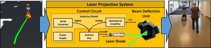
Fig. 1: A service robot projects its planned driving trajectory with the developed laser projection system onto the ground
to signalize a person on which side it wants to pass the human. Left: Internal data representation of the robot. Middle:
Projection system receives this information to control a laser diode and a beam deflection unit. Right: Resulting projection
in the environment.
Abstract— In order to deploy service robots in environments were performed, a user needs to keep a desired distance to
where they encounter and/or cooperate with persons, one the robot, in order to robustly estimate his or her gait patterns
important key factor is human acceptance. Hence, information and give reliable feedback. In this case, it could be beneficial
on which upcoming actions of the robot are based has to be
made transparent and understandable to the human. However, to project the area where the user is preferred to walk.
considering the restricted power resources of mobile robot plat- In other, less user-centered applications, like our project
forms, systems for visualization not only have to be expressive ROTATOR [1], where a robot is supposed to scan shelfs
but also energy efficient. In this paper, we applied the well- in a supermarket for out-of-stocks during opening hours, the
known technique of laser scanning on a mobile robot to create acceptance and subjective sense of safety could be increased
a novel system for intention visualization and human-robot-
interaction. We conducted user tests to compare our system to by visualizing the robot’s planned driving trajectory.
a low-power consuming LED video projector solution in order
to evaluate the suitability for mobile platforms and to get human For such visualization purposes, robotic applications from
impressions of both systems. We can show that the presented the literature, like [7–12], have already made use of video
system is preferred by most users in a dynamic test setup on projectors for human-robot interaction. However, these video
a mobile platform. projector solutions have some critical drawbacks for their
mobile applicability. Even though there are relatively low
I. INTRODUCTION
power consuming LED video projectors available at the mar-
The main focus of our research targets the development ket, like the Telefunken DLP400, which we have previously
and long-term deployment of robots for challenging real- utilized in our projects, this video projector (33W) still needs
world scenarios. The fields for application range from su- ≈ 15% of the total power consumption (≈ 220W) of our
permarket [1, 2] and clinical [3, 4] to domestic [5, 6] envi- robot. This reduces the robot’s effective operation time and,
ronments.In all cases, the transparency of the robot’s inner thus, is a suboptimal solution for long-term applications.
state as well as its intention should improve its acceptance Furthermore, due to the LED backlight technology there is
from users or other persons. In our project ROGER [3] for always an illuminated area and thus, power is always consu-
example, where robot-supported mobile walking exercises med, even when no information is projected (i.e. the video
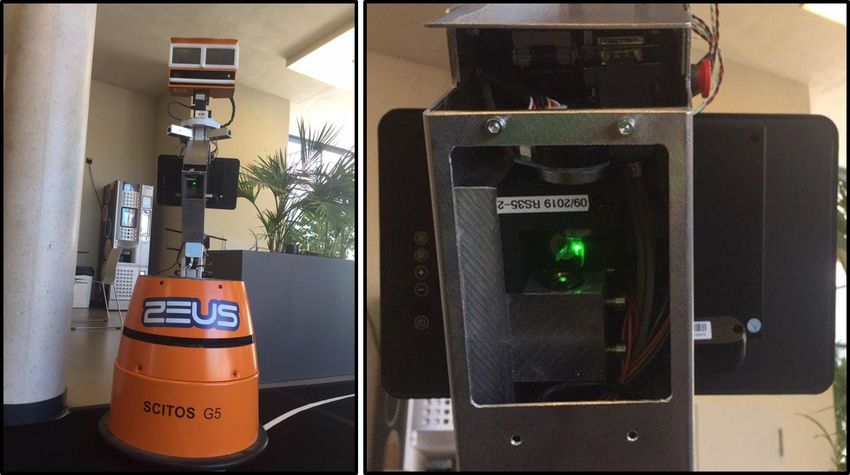
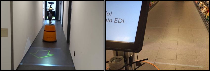
projector’s image is empty). This can also be problematic
This work has received funding from the German Federal Ministry of since this area may lead to misinterpretations by the users
Education and Research (BMBF) to the project 3D-PersA2 (grant agreement
no. 03ZZ0460), the project ROTATOR (grant agreement no. 03ZZ0437D) (see Fig. 2). Moreover, the opening angle of the LED video
as part of the research alliance 3DSensation and the project FRAME (grant projector is relatively small and the illuminescence is inverse-
agreement no. 16SV7829K). ly proportional to the square of the distance to the projector.
All authors are with Neuroinformatics and Cognitive Robotics
Lab, Ilmenau University of Technology, 98694 Ilmenau, Germany. This restricts the projections to an area directly in front
tim.wengefeld@tu-ilmenau.de of the robot. User tests in our shelf out-of-stock detection
Int. Symp. on Robot and Human Interactive Communication (RO-MAN), Naples, Italy, pp. 259-265, IEEE 2020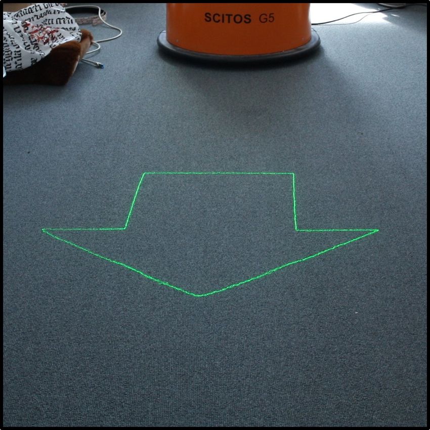
setups. Also in mobile applications, video projectors have
                                                                       been deployed in a wide variety of areas. In [8, 11] robots
                                                                       for guiding tasks that project useful information to users
                                                                       into the environment are described (e.g. the direction a user
                                                                       should look at). Other works made use of a video projector
                                                                       to visualize the robot’s driving behavior, either by projecting
                                                                       the desired driving direction [12] or the planned local path [9]
                                                                       in front of the robot. Considering service robots in domestic
Fig. 2: Robot and projections with the previously used LED             environments, [7] used a video projector in combination with
video projector solution. Left: Arrow visualization in our lab.        a Kinect2 sensor to project information about a recognized
Right: illuminated area in one of the targeted environments.           object onto the object’s 3D surface. Even video conference
                                                                       systems and workout supporting video projections have been
                                                                       deployed in an ambient assisted living scenario with a mobile
project with a Telefunken DLP400 [1] have confirmed these              robot [10]. However, while in static scenarios the power
disadvantages in a supermarket application. The brightness             consumption of a video projector is not an issue, in mobile
of the video projector is too low and, thus, users asked for           setups it is. An increased energy consumption leads to a
a higher contrast.                                                     lowered effective operation time and, thus, to a decreased
   In this paper, we present an alternative to conventional            effectiveness of the robot. In the following, we present an
video projector solutions for robotic applications based on            alternative to power consuming video projector solutions
a deflected laser beam. Deflecting a laser beam, also called           suitable for mobile applications.
laser scanning, is common practice in a wide field of appli-
cations, ranging from laser range measurements (lidar) over                          III. SYSTEM DESCRIPTION
barcode scanning to laser shows. However, to the best of our              The principle of laser scanning is to deflect a laser beam
knowledge, this technology has never been used for human-              in x- and y- direction, using two fast-rotating mirrors. In
robot-interaction on a mobile robot. The main advantages of            our system we use a so called galvanometer scanner for that
our system, in comparison to conventional video projector              purpose (see Fig. 1), that is controlled using several hard-
solutions, are as follows. Since the inverse-square law for            and software modules. For a projection, the scanner receives
light in form of a bundled laser beam is negligible, larger            a list of 2D coordinates on which the laser beam is pointed.
projection areas and distances can be achieved. In addition,           When all points are processed, the scanner repeats the list
our system is more energy efficient and requires only about            until a new projection shall be displayed. If the deflection
1/3 of the reference video projector’s power consumption at            is fast enough, the projection is perceived as a continuous
maximum.                                                               figure by humans.
   In summary, the contributions of this paper are:                       In the following, we describe this system more in de-
   • the development of a laser projection system suitable for         tail. First, we present the constructed hardware and the
      deployment on mobile platforms, consisting of a galva-           micro-controller that was integrated on our robot. Then, we
      nometer laser scanner, a self-designed circuit board, and        describe the software modules that transform the internal
      software to control the laser beam,                              data representation of the robot to a list of 2D points that
   • the publication of circuit board designs and micro-               is received by the deflector. Finally, we give an overview
      controller code to the scientific community1 ,                   of the implemented visualizations that were tested in the
   • an user evaluation of the laser projection system in              experimental section.
      comparison to a common LED video projector with
      respect to perceptibility and usability                          A. Hardware
                                                                          Our hardware construction consists of three independent
                    II. RELATED WORKS                                  main components, which are illustrated in Fig. 1: The laser
   Visual signals for human robot communication have been              diode, the beam deflection unit, and a control circuit. The
studied over the last two decades. Robots with artificial heads        first two are off-the-shelf components whereas the latter is
for example can signal their driving direction [13]. However,          a custom built circuit, that we made publicly available1 .
this is a relatively limited method for communication. Also            The system uses a standard USB interface, allowing an easy
blinking LEDs have been used for this purpose [14], but have           connection with our robots.
shown least understandability compared to other intention                 Laser diode: For a laser projector, the perceived bright-
cues like motion and speech. Robots with artificial eyes               ness of the projection depends on its size and the power of the
[15] may use facial expressions to show intentions, but                laser diode. Since, under normal lighting conditions, greenish
results have shown that they are hard to interpret by humans.          colors are perceived best by humans [18], we also decided in
The usage of video projector solutions for human robot                 favor of a green laser diode. For our experiments we used a
interaction has shown great advantages in static [16, 17]              5mW green laser diode of class 3R from TRU Components
                                                                       (LM05GND, 532nm wavelength). We have chosen a class
   1 https://www.tu-ilmenau.de/neurob/data-sets-code/laserprojector/   3R laser since it provides the highest brightness and is

                Int. Symp. on Robot and Human Interactive Communication (RO-MAN), Naples, Italy, pp. 259-265, IEEE 2020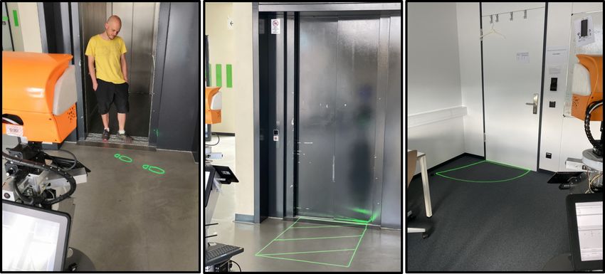
Fig. 3: Experimental construction of the laser projector:                     Fig. 4: Left: Final integration of the laser projection system
Beam deflection unit (a) and the laser diode (b) are mounted                  in an aluminum case on the ROTATOR robot [1]. Right:
onto an aluminum plate, our developed interface circuit (c)                   Closeup of the beam deflection unit.
with USB connection (d), the provided galvanometer control
unit (e) which comes with the beam deflection unit.
                                                                              of the Arduino Due. The shield includes a highly efficient
                                                                              switching power supply unit, which provides the stabilized,
classified as eye-safe for diffuse reflections2 . However, it                 symmetrical DC voltage needed by the beam deflection unit
should be avoided to intentionally stare into the direct                      (±18V) and the laser diode as well as the Arduino (+12V).
non-moving beam. Higher powered laser diodes offer even                       The input for the power supply unit is directly taken from
more brightness and could be integrated as well. However,                     the robot’s battery (+22.4V to +30.4V, depending on the
additional precautions need to be taken with laser classes 3B                 current state of charge). Furthermore, the shield includes a
and 4, as these lasers can easily cause damage to the human                   high-speed USB-to-Serial-Converter (F232RL from FTDI)
eye if they hit the human eye directly or indirectly.                         that is used to transfer the point lists via USB to the Micro-
   If more than one object shall be projected simultaneously,                 processor. To output the current projection and receive new
the mirrors need to move between these whilst the laser diode                 data from the robot simultaneously, we use two ring-buffers
is turned off, as otherwise a line would connect the objects.                 and interrupt-based programming on the microprocessor.
Thus the laser diode has to react to a control signal as fast                    The coordinates in the point lists (described in Sec. III-
as possible, i.e. within the time between consecutive points,                 B) are converted to analog signals by using the integrated
which we set to 50 microseconds. As our laser module does                     digital-to-analog converters (DACs) of the Arduino Due. The
not provide these low switching times with the supplied                       shield then transforms these low-voltage signals (0.55V to
driver, we replaced it with a logic level laser-driver. Hence,                2.75V) to the ILDA levels (±10V) using an operational am-
the laser diode’s current is regulated by the driver and the                  plifier circuit. In summary, our control circuit acts as an easy
control circuit only needs to provide a single binary signal                  to use interface between the robot’s software layer (Sec. III-
(e.g. 3.3V for laser on and 0.0V for laser off).                              B) and the aforementioned laser projector components. All
   Beam deflection unit: For beam deflection a K12n low-                      those components (Fig. 3) are mounted on our robot inside
cost-scanner from JMLaser is used. It consists of two high                    an aluminum case, providing a stable mounting of all parts
speed galvanometers which are each connected to a small                       as well as a proper cooling of the galvanometer driver circuit
mirror. We measured an optical opening angle of ±27◦ for                      and the laser diode (see Fig. 4).
both axes. Note that this is ±7◦ larger than declared in the
technical specifications of this module. The galvanometers                    B. Software
are controlled by an integrated circuit, that complies with                      In order to visualize internal data representations (e.g.
the ILDA3 interface specifications and thus, uses two analog                  the planned local path or a symbolic object) with the laser
signals (±10V ) as positional input for the two mirrors. The                  projector, they have to be transformed into x-y coordinates
conversion of the digital point lists from the robot to these                 (see Fig. 5), which are passed to the control circuit. The
analog signals is done by a control circuit that is described                 control circuit then converts these x-y coordinates to analog
in the following.                                                             signals (±10V), which correspond to specific angles of the
   Control circuit: To power and control the laser diode as                   mirrors. Furthermore, due to the mounting of the projector,
well as the beam deflection unit, we use an Arduino Due                       the projection has to be distorted according to its point of
ARM-based microcontroller in combination with a custom-                       view in order to meet the correct proportions in the environ-
designed arduino shield circuit, that can be plugged on top                   ment, e.g. on the ground. This is achieved by converting the
                                                                              data representation into a polygon (ordered list of 3D points).
    2 Note that laser safety regulations can be different for each country.
                                                                              To provide a uniform distribution of light in the environment,
We take no responsibility for damage of any kind caused from replicas of
our system or specific parts of it.                                           it has to be ensured that the points of the polygon are
    3 https://www.ilda.com/                                                   evenly distributed over their Euclidean 3D distance. If this

                 Int. Symp. on Robot and Human Interactive Communication (RO-MAN), Naples, Italy, pp. 259-265, IEEE 2020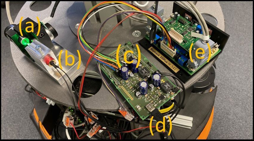
(a)                             (b)
Fig. 5: Left: Virtual arrow polygon in 3D world coordina-
tes. Middle: Backprojected corner points, which define the
polygon, in the image plane (yellow) and points that are
filled in between the corners (red). Right: Projection in the
environment.

is not the case inherently, e.g. for an arrow polygon which
is just defined by its corners, we automatically insert new
points every 5cm. Since each polygon is defined in its own                        (c)                             (d)
coordinate system, e.g. the robot’s coordinate system for the
planned local path polygon, the second step is to transform
all polygon points into the projector’s 3D coordinate system.
Finally, to generate the 2D point list for the laser projector,
each 3D point of the polygon is projected onto a virtual
                                                                                                  (e)
image plane using a pinhole camera model
                                                               Fig. 6: Various visualization examples of the laser projector:
                x2D        x3D /z3D · fx + cx
                      =                          .                 personal space and person orientation (a), personal space,
                y2D        y3D /z3D · fy + cy
                                                                   person orientation and planned path (b), driving direction
 The principal point c is assumed to be in the center of the       visualized as arrow (c), arbitrary symbol (d) and text (e).
projector cx = cy = 0.5. The focal length
                                      1
                   f = fx = fy =                                   user, e.g. that s/he shall push a button (see Fig. 6d), our
                                    tan(φ)                         system is further able to project symbols or text (see Fig. 6e).
can be determined using the known opening angle ±φ of the
beam deflection unit.                                                                   IV. EXPERIMENTS
                                                                      In all test setups, we used a 5mW green laser diode in the
C. Implemented Visualizations                                      developed laser projection system and a low power consu-
   To show the internal state and intentions of the robot,         ming Telefunken DLP400 as reference for video projector
we implemented several visualizations. To signal a person          solutions. A comparison of the technical parameters can
that s/he is perceived by the robot, we project the personal       be found in Table I. To evaluate both projection systems,
space [19] as circle around his/her feet. Furthermore, the         we conducted two kinds of test procedures. In the first
estimated upper body orientation is indicated by a small           one, the general visibility was evaluated in a static test
arrowhead (see Fig. 6a). For person perception, we use the         setup (see. Fig. 7 left). The second one was conducted to
tracking system proposed in [20]. The upper body orientation       evaluate the general usability, by performing dynamic tests
is estimated with the pointcloud and deep learning methods         on a mobile platform (see. Fig. 7 right). To ensure that
proposed in [21, 22]. To visualize the planned driving beha-       the given impressions were not influenced by the preceding
vior, we project either the planned global path [23, 24] or        experiment, both tests were conducted with different persons.
the local trajectory [25, 26], which is used for navigation        In total, we acquired 16 participants (10 male and 6 female)
purposes by our robot (see Fig. 6b). However, these path           and split them into two groups with equal size and gender
visualizations have relatively fast changing appearances and,      distribution for the static and dynamic tests. All of them
therefore, have shown to be likely misinterpreted in the           were between the age of 18 and 34 years, mostly students
dynamic user tests (Sec. IV-B). Hence, we implemented an           with little or no experience with robots. For both test setups,
alternative arrow visualization pointing to the desired locati-    we developed a questionnaire with a set of categorical
on that the robot will pass in the next second (see Fig. 6c)).     answers on a five point likert scale. Possible answers were
To give additional application-specific information to the         Strongly Agree (SA), Agree (A), Neither Agree Nor Disagree

              Int. Symp. on Robot and Human Interactive Communication (RO-MAN), Naples, Italy, pp. 259-265, IEEE 2020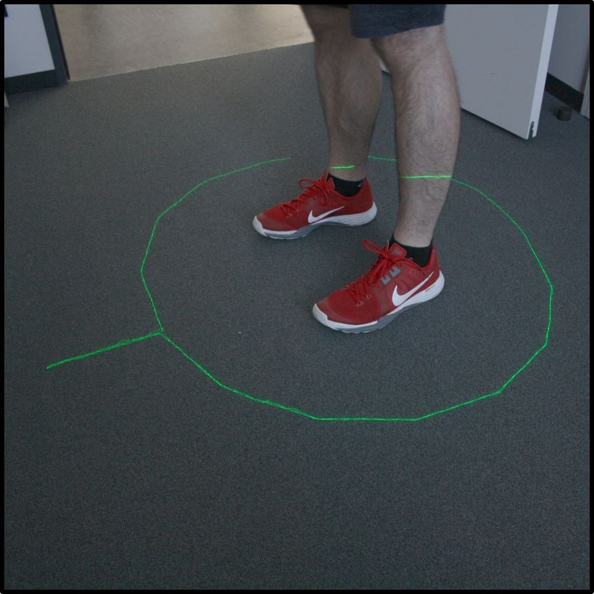
LED Video Projector
                                                                           SA
                                                                                                                      Laser Projector
                                                                                        4.38
                                                                                 4.00
                                                                           A

                                                                                                                            3.12 3.25
                                                                        NAND                            2.88 2.75

                                                                           D

                                                                          SD
                                                                                    SQ1                   SQ2                  SQ3

                                                                                    Laser Projector      Neutral      LED Video Projector

                                                                         SQ4                    62.5%               12.5%     25.0%
                                                                         SQ5            37.5%               37.5%             25.0%
                                                                            0%                                                          100%
Fig. 7: Left: Placement of the first prototype of the developed
laser projector (a) and reference LED video projector (b)               SQ1      The laser projector / LED video projector provides a
                                                                                 good visibility on the light-colored floor covering.
at the robot in the experimental static test setup. Right:
                                                                        SQ2      The laser projector / LED video projector provides a
A person passing the robot while the planned trajectory is                       good visibility on the dark-colored floor covering.
projected to the ground in the dynamic test setup.                      SQ3      The laser projector / LED video projector provides a
                                                                                 good visibility on the dark-colored carpeting.
                                                                        SQ4      Which kind of projector generates more attention?
(NAND), Disagree (D), Strongly Disagree (SD). Beside                    SQ5      Which projector would you prefer to communicate in-
                                                                                 formation?
these categorical questions, in both experimental series the
participants were asked to give a general preference for               Fig. 8: Results (mean) of our static test questionnaire (top)
either the laser projector or the LED video projector. They            and corresponding questionnaire items (bottom). Whiskers in
were supposed to choose only one answer for each question.             the top figure indicate the standard deviation.
Furthermore, it was also possible to give general impressions
or additional notes in an interview after the experiments.
                                                                       the same question was answered indifferent. Furthermore,
A. Static tests                                                        the test subjects have shown no clear preference for either
   In the static test setup, we evaluated the general visibility       the laser projector or LED video projector solution. Three
of the developed laser projector in comparison to the previous         participants stated that they preferred the thicker contours of
LED video projector solution on different coverings. The               the LED video projector, which the laser projector is not able
participants were free to walk around to assess the projec-            to display. One participant even preferred the illuminated
tions from different points of view. All possible visualiza-           area of the video projector since it generates more attention.
tion options for symbols, text, and the planned trajectory             In conclusion for this test setup, the developed laser projector
(see Fig. 6) were projected consecutively onto one specific            does not achieve a significantly better acceptance than the
ground. After that, the participants filled out one item of the        previously used LED video projector. So, the only advantage,
questionnaire, and the ground was changed to the next one.             which remains for the laser projector, is the lower power
We tested three floor coverings ranging from light- and dark-          consumption in such a static setup. With these findings, we
colored floor coverings to a dark carpeting ground. Results            wanted to evaluate the usability in a dynamic test setup where
and items of the static questionnaire (SQ) are shown in Fig. 8.        other characteristics, like the increased opening angle and
It can be seen, that in this static test setup, the visibility for     scene dynamics, came into play.
both projection solutions was rated as good for light-colored
floor grounds. For the dark-colored floor covering and carpet,         B. Dynamic tests
                                                                          For this test setup, an evasion situation between a robot
                                                                       and a person was initiated. The participants were asked to
 Tech. specs.
                       LED video projector          Developed          walk in a straight line to a goal behind the robot (no further
                           (DLP400)          laser projection system   instructions were given) while the robot was driving to a
 opening angle          ±22◦ H ±13◦ V               ±27◦ H/V
                                                   5.6W (idle)         goal behind the participant. After the encounter, the persons
 power consumption            33W
                                               10W (in operation)      were asked to answer questions about their experiences in the
 colors                        RGB            curr. monochromatic      situation. During these tests, the robot’s driving behavior was
                          decreases with          decreases with
 brightness                                                            influenced by persons around him, utilizing an asymmetrical
                             distance            vis. complexity
                                                                       personal space cost function around detected persons. With
TABLE I: Comparison of the technical specifications of                 this driving behavior enabled, the robot avoided to get
the LED video projector and the developed laser projection             in close proximity to the persons and preferred to pass
system used in the experiments.                                        persons on the right side, like in a human-human passing-

                 Int. Symp. on Robot and Human Interactive Communication (RO-MAN), Naples, Italy, pp. 259-265, IEEE 2020
SA
          4.50      4.62                   4.62
                                                   4.38
                                                              4.12
    A
                               3.38

 NAND

    D

   SD
          DQ1       DQ2        DQ3         DQ4     DQ5        DQ6
                                                                            Fig. 10: Further visualizations in our ongoing work. Left:
             Laser Projector         Neutral      LED Video Projector       walking feet animation to tell a person to leave the elevator.
  DQ7                  62.5%                          37.5%                 Middle: restricted area no one should enter when the robot
  DQ8                          87.5%                          12.5%         enters the elevator. Right: opening animation to signalize that
     0%                                                              100%   the robots wants to pass the door and requires help [27].
 DQ1      The movements of the robot become more predictable
          through the projection of a projector.
 DQ2      I find the information transfer of the robot through a            while one participant was neutral. This can be explained by
          projector to be good.
 DQ3      With a projector, the robot can gain the trust of humans
                                                                            analyzing the specific remarks from the participants from
          more quickly.                                                     the interviews. Even though, 3 participants stated that the
 DQ4      The path trajectories shown bring added value to the              LED video projector attracts more attention through the
          interaction with the robot.                                       illuminated square in front of the robot, this was found to be
 DQ5      The projections make me feel safer.                               confusing (4 participants) in the tested situation. One partici-
 DQ6      The projections give me the feeling of being perceived            pant even misinterpreted the illuminated square to be scanned
          by the robot.
 DQ7      Which type of projector generates more attention for              by the robot. Three participants stated that the visualization
          the situation played through?                                     of the planned path is beneficial when interpreting the driving
 DQ8      Which type of projector is better suited for the situation        behavior. ”The projection helps with decision making and
          played through?                                                   takes away the fear of getting closer to the robot” (TP06).
Fig. 9: Results (mean) of our dynamic test questionnaire (top)              However, also three participants found the path projection
and corresponding questionnaire items (bottom). Whiskers in                 difficult to interpret at first and asked for an alternative vi-
the top figure indicate the standard deviation.                             sualization. Therefore, we implemented an arrow projection
                                                                            to indicate the driving direction (see Fig. 6c). However, an
                                                                            evaluation of this new visualization remains part of future
                                                                            work. The visualization of the personal space was mostly
by situation. For a more detailed description of the utilized               found to be useless, since it was either not recognized or too
driving behavior we refer to [1]. The aim of this experiment                late to achieve the intended effect (8 participants).
was to show that the visualization of the driving intention and
environmental perception can increase the user acceptance.                           V. CONCLUSION & FUTURE WORK
To visualize the driving intention of the robot, we project                    In this paper, we have presented a novel approach for
the planned path. To signal a person that s/he is perceived                 projecting information into the surroundings of a mobile
by the robot, we utilized the personal space visualization                  robot using a laser projection system. The presented system
(see Fig. 6a). The experiment was repeated three times, once                is easy to integrate on any mobile platform that provides
with no projections, once with the LED video projector,                     the needed power supply and an USB port for controlling.
and once with the laser projector. Results and items of the                 We compared the laser projector with a convenient LED
dynamic questionnaire (DQ) are shown in Fig. 9. These                       video projector solution suitable for robotic applications. We
results indicate, that projections in general add value to                  performed an assessment of the perceptibility and usability
a human-robot-interaction. The participants stated that the                 in two user test scenarios. Results show, that, even though the
movements of the robot became more predictable, they felt                   laser projector with a 5mW diode is preferred en par with the
saver and perceived by the robot through the utilized projecti-             LED video projector in a static test setup, it achieves a higher
ons. Only the question whether the projections can increase                 acceptance in dynamic HRI situations. Reasons for this are
the trust of humans was answered indifferent. The reason                    the wider opening angle as well as the higher brightness
for this might be the inexperience of the participants with                 at greater distances. Moreover, since the laser projector does
robots in combination with our relatively large experimental                not illuminate the whole projection area, users are less likely
platform. However, more interesting was the result of the                   confused. An additional advantage is the lower power con-
preference question (DQ8). In contrast to the static tests,                 sumption, which allows an increased uptime of robots in the
in this experimental setup 7 of 8 participants preferred the                application compared to a classic video projector. However,
laser projector instead of the LED video projector solution                 these user tests just give an initial subjective assessment

                 Int. Symp. on Robot and Human Interactive Communication (RO-MAN), Naples, Italy, pp. 259-265, IEEE 2020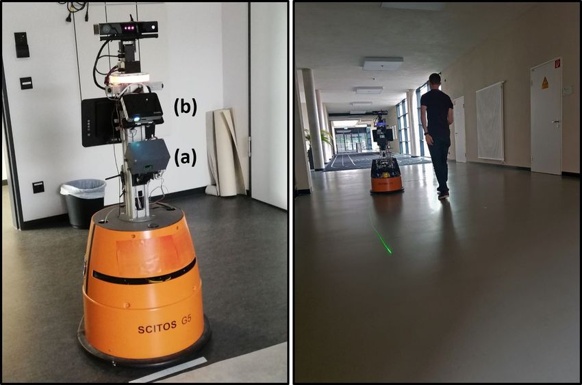
[6] H.-M. Gross, et al., “Robot Companion for Domestic Health Assistan-
                                                                                    ce: Implementation, Test and Case Study under Everyday Conditions
                                                                                    in Private Apartments,” in Proc. of IROS, 2015, pp. 5992–5999.
                                                                                [7] M. Foukarakis, et al., “Applying a multimodal user interface develop-
                                                                                    ment framework on a domestic service robot,” in Proc. of the 10th Int.
                                                                                    Conf. on PErvasive Technologies Related to Assistive Environments,
                                                                                    2017, pp. 378–384.
                                                                                [8] R. Stricker, et al., “R2D2 Reloaded: Dynamic Video Projection on a
                                                                                    Mobile Service Robot,” in Proc. of ECMR, 2015, pp. 1–6.
                                                                                [9] R. T. Chadalavada, et al., “That’s on my mind! robot to human
                                                                                    intention communication through on-board projection on shared floor
                                                                                    space,” in Proc. of ECMR, 2015, pp. 1–6.
                                                                               [10] P. Panek, et al., “User acceptance of a mobile led projector on a
                                                                                    socially assistive robot,” in Ambient Assisted Living. Springer, 2012,
Fig. 11: Comparison between a 5mW and a 40mW laser                                  pp. 77–91.
                                                                               [11] T. Sasai, et al., “Development of a guide robot interacting with the
diode. Left: The 5mW diode from the user tests. Right: The                          user using information projection — Basic system,” in IEEE Int. Conf.
currently installed 40mW diode for our future work.                                 on Mechatronics and Automation, 2011, pp. 1297–1302.
                                                                               [12] T. Matsumaru, “Mobile Robot with Preliminary-announcement and
                                                                                    Display Function of Forthcoming Motion using Projection Equip-
                                                                                    ment,” in Proc. of RO-MAN, 2006, pp. 443–450.
of the tested age group in a lab environment. We plan a                        [13] S. Yamashita, et al., “Evaluation of Robots that Signals a Pedestrian
                                                                                    Using Face Orientation Based on Moving Trajectory Analysis,” in
more extensive user study in the targeted environment [1]                           Proc. of RO-MAN, 2019, pp. 1–8.
with a larger amount of participants and objective measures,                   [14] M. Neggers, et al., “Investigating the Understandability and Efficiency
like the change of reaction times when passing the robot.                           of Directional Cues in Robot Navigation,” in Proc. of RO-MAN, 2019.
                                                                               [15] T. van der Grinten, et al., “Designing an Expressive Head For a Help
Furthermore, in upcoming user tests (planned in August                              Requesting Socially Assistive Robot,” in Human-Friendly Robotics
2020) with our FRAME robot [27] we will evaluate the                                (HFR) 2019. Springer, 2020, pp. 88–102.
intention indication when asking a user for assistance to pass                 [16] A. Hietanen, et al., “Proof of concept of a projection-based safety
                                                                                    system for human-robot collaborative engine assembly,” in Proc. of
closed doors or using an elevator (see Fig. 10). Currently,                         RO-MAN, 2019.
we are working on the integration of a more advanced                           [17] G. Bolano, et al., “Transparent Robot Behavior Using Augmented
beam deflection unit (Raytrack 35+ by JMLaser). Despite an                          Reality in Close Human-Robot Interaction,” in Proc. of RO-MAN,
                                                                                    2019, pp. 1–7.
increased opening angle of ±37◦ H/V (measured), this unit                      [18] L. T. Sharpe, et al., “A luminous efficiency function, V*(λ), for
also provides an integrated laser safety circuit. The deflector                     daylight adaptation,” Journal of Vision, vol. 5, no. 11, pp. 3–3, 2005.
calculates the beam’s speed from signals provided by our                       [19] E. T. Hall, “A system for the notation of proxemic behavior,” American
                                                                                    anthropologist, vol. 65, no. 5, pp. 1003–1026, 1963.
interface (target position) as well as the current mirror angle                [20] T. Wengefeld, et al., “A Multi Modal People Tracker for Real Time
(actual position). If a minimum distance is ensured between                         Human Robot Interaction,” in Proc. of RO-MAN, 2019, p. 8 pages.
the user’s eye and the beam deflection unit, a minimum speed                   [21] T. Wengefeld, et al., “Real-time Person Orientation Estimation using
                                                                                    Colored Pointclouds.” in Proc. of ECMR. IEEE, 2019, p. 7 pages.
for eye safety can be determined. The safety circuit ensures                   [22] B. Lewandowski, et al., “Deep orientation: Fast and Robust Upper
that the laser diode is only switched on if the current speed                       Body orientation Estimation for Mobile Robotic Applications,” in
is above the minimum speed for eye safety. This allows the                          Proc. of IROS, 2019, pp. 441–448.
                                                                               [23] R. Philippsen et al., “An Interpolated Dynamic Navigation Function,”
safe usage of higher powered laser diodes and, thus, a better                       in Proc. of ICRA, 2005, pp. 3782–3789.
perceivability. Moreover, the power consumption of the diode                   [24] E. W. Dijkstra, “A note on two problems in connexion with graphs,”
is negligible in comparison to the rest of the system. First                        Numerische mathematik, vol. 1, no. 1, pp. 269–271, 1959.
                                                                               [25] St. Mueller, et al., “Local Real-Time Motion Planning Using Evo-
preference tests have shown a much greater acceptance for a                         lutionary Optimization,” in Towards Autonomous Robotic Systems
system with a 40mW diode (see Fig. 11). Furthermore, we                             (TAROS), ser. LNCS, vol. 10454. Springer, 2017, pp. 211–221.
plan to integrate an RGB laser module, consisting of three                     [26] D. Fox, et al., “The dynamic window approach to collision avoidance,”
                                                                                    IEEE Robotics Automation Magazine, vol. 4, no. 1, pp. 23–33, March
laser diodes and two dichroic mirrors for beam merging,                             1997.
which will make it possible do project colored symbols.                        [27] J. Liebner, et al., “Now i need help! passing doors and using elevators
                                                                                    as an assistance requiring robot,” in Int. Conf. on Social Robotics
                                                                                    (ICSR). Springer, 2019, pp. 527–537.
                             R EFERENCES
 [1] B. Lewandowski, et al., “Socially Compliant Human-Robot Interaction
     for Autonomous Scanning Tasks in Supermarket Environments.” in
     Proc. of RO-MAN, 2020.
 [2] H.-M. Gross, et al., “TOOMAS: Interactie Shopping Guide Robots in
     Everyday Use – Final Implementation and Experiences from Long-
     Term Field Trials,” in Proc. of IROS, 2009, pp. 2005–2012.
 [3] Th. Q. Trinh, et al., “Autonomous Mobile Gait Training Robot for
     Orthopedic Rehabilitation in a Clinical Environment.” in Proc. of RO-
     MAN, 2020.
 [4] H.-M. Gross, et al., “Mobile Robot Companion for Walking Training
     of Stroke Patients in Clinical Post-stroke Rehabilitation,” in Proc. of
     ICRA, 2017, pp. 1028–1035.
 [5] H. M. Gross, et al., “Living with a Mobile Companion Robot in your
     Own Apartment - Final Implementation and Results of a 20-Weeks
     Field Study with 20 Seniors,” in Proc. of ICRA, 2019, pp. 2253–2259.

                 Int. Symp. on Robot and Human Interactive Communication (RO-MAN), Naples, Italy, pp. 259-265, IEEE 2020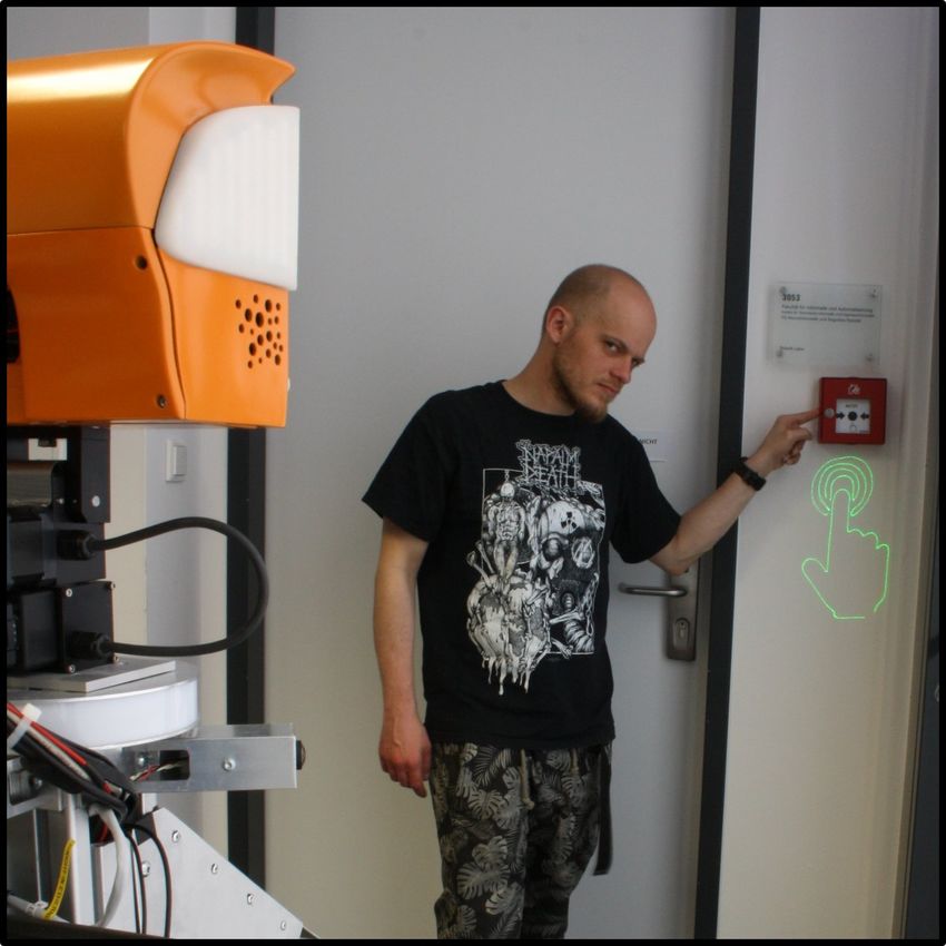
You can also read