Development of flume model of inclined capillary barrier (clay silt/CDW) in a subtropical climate scenario - MATEC Web ...
←
→
Page content transcription
If your browser does not render page correctly, please read the page content below
MATEC Web of Conferences 337, 04007 (2021)                                                           https://doi.org/10.1051/matecconf/202133704007
PanAm-UNSAT 2021

             Development of flume model of inclined capillary barrier (clay
             silt/CDW) in a subtropical climate scenario
             Thays C.F. Oliveira1,*, Bianca G.S. Dezen1, and Julio C. Bizarreta-Ortega1
             1Universidade  Federal da Integração Latino-Americana (UNILA), Instituto Latino-Americano de Tecnologia, Infraestrutura e
             Território (ILATIT), Foz do Iguaçu, Brasil

                           Abstract. Interest in research on capillary barrier (CB) in regions with humid climates (tropical and
                           subtropical) is increasing. One of the main advantages of such cover type is the greater flexibility
                           regarding the materials that could compose it. A possibility is the use of construction and demolition
                           wastes (CDW), which would contribute to the solution of CDW destination, a problem in urban
                           centers. Thus, the present work aimed an experimental evaluation of CB cover with CDW in its
                           composition. A CB cover system was reproduced in a physical model in acrylic box, with clay soil as
                           capillary layer and CDW as capillary block, given its granulometric and hydraulic contrast. The layers
                           were arranged with the usual landfill slope, of 1:3, and a very heavy rain, of 90 mm, was simulated.
                           Three tests were performed on the flume model, in which initial CDW saturation degree (S0) was
                           varied in 4,5%, 10,3% and 17,3%. Results indicate formation, indeed, of capillary barrier between the
                           two used materials. The most efficient model was the one with lowest initial CDW S 0, of 4,5%. As
                           the CWD S0 increased, time of flow permanence at materials interface decreased, indicating a CWD
                           S0 in which such capillary barriers no longer function effectively. Regarding percolation rate, the
                           maximum for a 90 mm rainfall was 2,7%, which fits the landfill cover projects criteria consulted.

       1 Introduction                                                         the infiltration of the non-drained water); and, finally, gas
                                                                              collection and foundation layer ([2] and [3]).
       The Urban Solid Waste (USW) production in Brazil is                        The classic applied materials for the various final
       annually analyzed and quantified through the cooperation               cover layers of a landfill are: low permeability soils (for
       of competent agencies (e.g., ABRELPE and IBGE) along                   hydraulic barrier layers); gravel or other inert material (for
       with the Brazilians city halls. Only in the year of 2018, an           drainage and gas collection layers); and, geosynthetic
       waste amount of 216,6 ton/day was collected in the                     materials [4].
       country (collect coverage of 92%), where the total amount                  Regarding the barrier materials, generally, compacted
       is 79 millions of tons and the per capita production                   clay soils (Ksat ≤ 1E-7 cm/s) are employed, however, with
       average is 380 kg/year [1].                                            this technique, contraction cracks manifestation in the
           Still according to ABRELPE [1], out of this collected              clay layer are common, due to wetting and drying natural
       quantity, 59,5% of the wastes were sent to landfills. This             processes, which can considerably affect the whole
       value, when compared to the one of 2007, represents an                 system efficiency.
       expressive increase (20,9%) of USW disposition in                          As a solution for this problem, an alternative final
       landfills. In this context, research concerning USW                    cover system is a cover with capillary barrier effect. In
       landfills is extremely important, once it is necessary to              this system, the contrast of the non-saturated hydraulic
       assure its good functionality, due to the specificities of             properties of two different granulometric overlapped
       these constructions, that are being each time more                     layers is explored, where the superior one is formed by a
       required.                                                              thinner material (capillary layer) and the inferior one is
           Regarding the landfills, one of their main                         composed by a coarser particle size material (capillary
       particularities is the final covers systems. These are                 block), in order to create a barrier in the interface of these
       extremely important, especially considering their function             layers due to accentuated suction and hydraulic
       of minimize the rainfall infiltration and its percolation into         conductivity contrasts [5].
       the residues mass. It is important to highlight that the                   The mentioned system works in an unsaturated flow
       refereed system directly influences in the leachate                    regime. When the water flows in this regime, a delay in
       production and, ideally, they should be constituted by                 vertical percolation occurs due to the abrupt change in the
       several layers, which are: surface layer; protection layer             substrate pores size (interface between capillary layer and
       (that stores percolated water from the superior layer);                capillary block). The macropores of the capillary block
       drainage layer (that promotes the lateral flow of the                  offer less “attractiveness” for the water than the
       percolated water); hydraulic barrier layer (which prevents             micropores of the material from the capillary layer
                                                                              itself [6].

             *
                 Corresponding author: thayscarf@gmail.com

  © The Authors, published by EDP Sciences. This is an open access article distributed under the terms of the Creative Commons Attribution License 4.0
  (http://creativecommons.org/licenses/by/4.0/).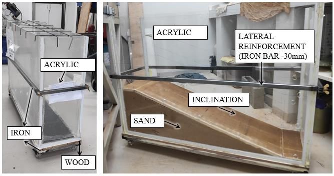
MATEC Web of Conferences 337, 04007 (2021)                                                       https://doi.org/10.1051/matecconf/202133704007
PanAm-UNSAT 2021

           In addition, an especially important parameter that              where the present research was developed). The materials
       needs to be considered in the capillary barrier systems              applied in the study were the CDW (as cappilary block)
       (CBSs) for landfills is its inclination. Kämpf &                     and the soil available in the region (clay silt, as capillary
       Montenegro [7] emphasize that the inclination contribues             layer).
       to a more effective operation of the CBSs and Aubertin et                An interesting point of this work is the use of CDW,
       al. [8] mention that the knowledge of this aspect of the             once large volumes of this materials are constantly being
       capillary barriers is of interest, once that cover systems           produced and solutions for the reincorporation of this
       able to deal with a bigger water volume. This advantage              material in the construction industry are required (as use
       of inclined CBS occurs due to what is called lateral                 in paving, concretes and landfills components). In
       diversion.                                                           addition, in the city where the research was developed, the
           Concerning the barrier effect failure, Harnas et al. [9]         CDW is not diposed in inert landfills as recommend by
       point that in regions with more humid climate (tropical              environmental regulations, but in the same landfill of the
       and subtropical ones, as is the case of the region in study),        city USW, which represents a serious problem to the city
       where the rainfall rates exceeds 1000 mm annually, the               USW management that need to be solved.
       breaking of the barrier effect happens much more faster
       and the adoption of measures or different approaches to
       maintain the system working for a longer time is required.           2 Material and methods
           One of the alternatives indicated in the literature is the       The present work was divided in two main stages, where
       use of different materials from the traditional ones for the         the first was the collect of the materials that were used in
       CB layers, in general, materials available in large amounts          the research (soil and CDW) and its physical and
       in the landfill’s proximity and that do not have an                  hydraulic characterization, and the second, the
       adequate destination.                                                development of the reduced physical model (flume
           One example of these materials is the Construction               model) for the inclined capillary barrier simulation in
       and Demolition Waste (CDW). Both Barros [10] and                     subtropical climate conditions (climate of the region of
       Bizarreta & Campos [5] indicate the potential for the joint          study).
       application of CDW fine fraction (< 4,8 mm) and clay soil
       as an alternative technique for the final covers in landfills,
       exploring its non-saturated properties for capillary barrier         2.1 Materials characterization
       systems. However, both works evaluated the properties of
       CDW in an isolated way, pointing for its potential of                The used materials were the residual soil from the region
       application in USW and the need of complementary                     (applied as capillary layer in the flume model) and CDW
       studies was identified, studies that evaluate the system             (applied as capillary block). Both materials were collected
       considering the flow that runs through the constituent               in the Urban Solid Waste Landfill (USWL) in Foz do
       layers.                                                              Iguaçu. The collected soil is available around the USWL,
           An interesting and widespread technique for this type            which is the same that is used in the procedures of daily
       of evaluation, that is, the flow behavior through different          and final covers. The CDW is collected from all places of
       layers, are the reduced physical models (flume models).              the city and directed to the USWL, once the city does not
       This study approach was adopted by several authors over              have a specific destination for this type of material. These
       the years, as [7], [11], [12], [13], [14], [15], among others.       residues are disposed in piles without separation between
           Almeida [12] and Izzo et al. [13], for example, studied          coarse and fine fractions. For this reason, the sifting in
       a CB cover system produced with solid waste pre-treated              loco of this material was needed, in the mesh #4 (4,8mm).
       mechanically and biologically, both carried out their                After collect process, all the material was stored with
       researches with the flume model technique. Almeida [12]              hygroscopic humidity in plastic baskets or in fabric bags,
       built a box of 20 mm glass plates, dimensions of 0,60 m              in a climatized chamber with temperature varying
       (width) x 1,96 m (length) x 0,97 m (height); rainfall                between 20 to 24ºC, in order to use it in the following
       simulator system made with PVC pipes with drippers;                  steps.
       and, three drain points (PVC pipes wrapped in geotextil                  The characterization of both materials was made
       membrane and gravel), two in each layer foot of the CBS              according to the current Brazilian standards and/or
       and one for runoff. Izzo et al. [13], on the other hand, built       according to literature recommendations, as follows:
       a 0,6 m x 1,80 m x 0,44 m acrylic box; for the rainfall                   x Specific mass: NBR 16605 [16];
       simulator system, sprinklers were employed; and the                       x Granulometry: NBR 7181 [17];
       drains were also made of PVC pipes. Zhan et al. [14]                      x Compaction curve: NBR 7182 [18];
       analysed a three-layer inclined capillary barrier (with                   x Saturated permeability coefficient: NBR 14545
       classical materials, silt, sand and gravel, respectively from                  [19] for soil and NBR 13292 [20] for CDW;
       top to bottom). Their physical model was built with acrilic               x Soil-water characteristic curve: Villar [21] and
       plates, dimensions of 1,0 m x 2,0 m x 1,2 m, rainfall                          Bizarreta [22].
       simulator with sprinklers and drains of PVC pipe wrapped                 Samples separation and preparing processes were
       in a wire mesh.                                                      executed according to NBR 6457 [23], except for the soil-
           Therefore, this works aims to develop a reduced                  water characteristic curve test, where the samples were
       physical model in order to study the CB effect in inclined           extracted from the flume model (after the capillary barrier
       cover systems in humid climate region, specifically, a               simulation test), which will be detailed in the following
       subtropical climate, as the one of Foz do Iguaçu-PR (city            section.

                                                                        2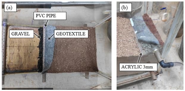
MATEC Web of Conferences 337, 04007 (2021)                                                         https://doi.org/10.1051/matecconf/202133704007
PanAm-UNSAT 2021

       2.2 Flume model

       The inclined flume model was developed aiming the
       simulation of a capillary barrier made of soil and CDW
       under conditions of intense rainfall, which frequently
       occurs in subtropical regions. The study of the capillary
       barrier behavior through flume models is an approach that
       had been being used by many authors ([7], [11]; [12];
       [13]; [14]; [15]), although it is not standardized. It is based
       in the execution of the layers of a CBS in a box or in
       specific apparatus, where rainfall events are simulated for
       measurements of percolated water volume over time.
       Such percolated water measurements are made in the
       different system layers through drains (and in some cases             Fig. 2. Flume model assembly.
       through sensors), where these are inserted in different
       positions of the box/apparatus.                                          Finally, a lateral reinforcement for the box was
           In the present work, the flume model was designed/                produced, to avoid its arching due to the material filling
       developed with 0,3 (width) x 1,0m (length) x 0,7m                     and compaction processes. This reinforcement was made
       (height), with lateral faces in 10mm acrylic plaques and              with 30mm iron bars, the same ones used in the box
       bottom in a 12mm wooden plate reinforced with 30mm                    bottom (under the wooden plate).
       iron bars. The design can be seen in Figure 1.
                                                                             2.2.1 Drains

                                                                             For the flume model of the present work, six (06) drains
                                                                             were used for system monitoring of runoff and percolated
                                                                             water volumes: three (03) for the vertical percolation
                                                                             measurement (Figure 1, drains A, B and C); two (02) for
                                                                             the horizontal percolation, in the layer’s foot, capillary
                                                                             (soil) and block (CDW) (Figure 1, drains D and E); and,
                                                                             one (01) for runoff. The drains were made with 20mm
                                                                             PVC pipes perforated along the water collect length and,
                                                                             specifically for the runoff drain, an opening along its
                                                                             whole length was made, due to the greater water volume
                                                                             that was going to be collected (Figure 3).
       Fig. 1. Flume model design.

            The acrylic plaques/wood plate were fixed together by
       “U” aluminum profiles and by elastic adhesive based in
       silyl modified (SM) polymer. Then, the wooden plate was
       impermeabilized        with      asphalt     emulsion      and
       impermeabilization tests were made, by filling the box
       with water and verifying the possible existing leaks.
            After the tightness verification of the box, this one was
       filled with sand in order to “mold” the inclination 1:3
       (H:V), 18º approximately, value that is usual for landfills
       slopes. Above the sand, another wooden plate was
       installed to isolate this material, and the contact between           Fig. 3. Drains. (a) Drain C. (b) Drain E.
       the wood and the acrylic was sealed with silicone. In this
       step, another impermeabilization test was carried out. The                For the installation of the drains in the box, holes in
       initial box assembly can be seen in Figure 2.                         the acrylic plaques were made previously to its fixing with
                                                                             the wooden plate. Also, PVC pipes passed through the
                                                                             two box faces, letting the drain with an inclination to the
                                                                             side of water collect.
                                                                                 During the experimental molding, the drains were
                                                                             wrapped in a gravel layer (draining material) under a
                                                                             geotextile layer (filtering material), as showed in
                                                                             Figure 3.a. The drains A, B and C (collect of the vertical
                                                                             percolation in the CDW layer) were tested before the
                                                                             material was put in the box. For the superior drains
                                                                             (bottom capillary layer and runoff), an impermeable
                                                                             material was used under the drain (3mm acrylic plate,
                                                                             Figure 3.b) in order to avoid the flow of the accumulated

                                                                         3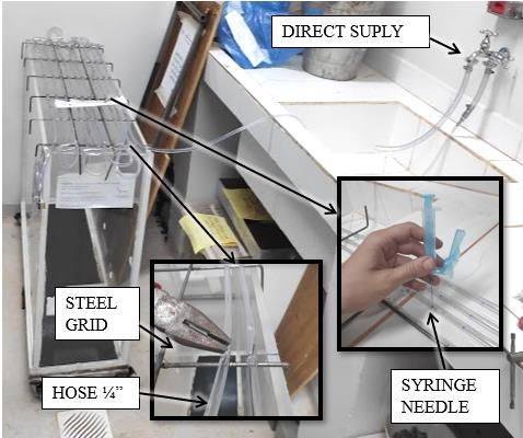
MATEC Web of Conferences 337, 04007 (2021)                                                        https://doi.org/10.1051/matecconf/202133704007
PanAm-UNSAT 2021

       water in these points into the lowers layers without the               Table 1. Tests description. (w: moisture content; irain: rain
       appropriated collect.                                                                intensity; volT.: total volume)

                                                                                      CDW            CDW             irain       Rain volT
                                                                            Test
       2.2.2 Rainfall simulator                                                       S0 (%)         w (%)         (mm/h)         (mm)
                                                                             E1         4,5           1,5*          91,8          210,7
       Regarding the rainfall simulation system, a ¼” flexible                                         3,5           101,5         208,0
                                                                             E2         10,3
       hose with small holes was used, fixed in a steel welded
                                                                             E3       17,3             5,9           91,1          121,4
       grid, aiming a better directing of the rain to the barrier
       (and not to the contact soil-acrylic, as it may occur in the        *hygroscopic moisture
       sprinkler cases) (Figure 4).
                                                                               Despite initial definition of a 90mm rain, in the cases
                                                                           where no percolated volume was measured by the drains,
                                                                           the rainfall phenomenon was extended until the drain
                                                                           activation. For this reason, Table 1 shows a real value of
                                                                           rain volume, which corresponds to the “Rain vol T”
                                                                           column.
                                                                               The real value of rain volume of the test is bigger than
                                                                           the idealized conditions and it is a little bit far away from
                                                                           the reality presented in the historical data, but, in the other
                                                                           hand, the system was subjected to very extreme
                                                                           conditions. NG et al. [15] also simulated a torrential
                                                                           rainfall event, in which intensity was 73,8 mm/h during
                                                                           4h, totalizing an amount of 295,2 mm of rain.
                                                                               While the test was being executed, the periods of
                                                                           water percolation in the soil and CDW layers were
                                                                           registered, as well as the permanency period in the CB and
                                                                           the operation beginning period of each drain. Also,
       Fig. 4. Rainfall simulator system.                                  volume measurements of the drain collect were performed
                                                                           every 10 min in the experiment for the initial 2 hours.
           The rainfall simulator system was designed to cover             Posteriorly, the collect volume of each drain after 4h, 8h
       85% of the initial stretch of the flume model, because the          and 24h were measured, regarding the initial beginning
       rainfall occurrence in 100% of the box area could                   time test and it could be verified that only the drain D
       camouflage the runoff and the percolation results. The              (capillary block foot) operated after the rainfall event
       hose holes were made with a syringe needle (small                   ended.
       diameter), in order to avoid a torrential rain.
           A volume of 90mm rain was fixed, based in the 20-
       year rainfall historical data survey (jan/1998 a dez/2018)          3 Results and discussion
       of Foz do Iguaçu – PR, compiled from the Paraná
       Meteorological System-SIMEPAR [24]. This volume                     3.1 Materials characterization
       represents strong rainfalls (above 50mm) according to
       Moreira [25] classification, which corresponds to 5,9% of           The material granulometric curves and the Atterberg
       all the rainfall events within the 20-year range analyzed.          limits indicate that the soil that was used in the present
       Within this 5,9% of very heavy rain events, rainfalls               work is a low plasticity sandy clay, CL (according to the
       above 90mm represents less than 1% of the rainfall                  USCS classification). The CDW can be classified as a
       events, therefore, this was the maximum value (limit)               silty sand, SM. These results are shown in Figure 5.
       fixed for the tests in the present work.

       2.2.3 Flume model test methodology
       For molding the test/experiment the layers were
       compacted with a laboratory-made tool, aiming a
       compaction degree (CD) of 80% for the soil. This value
       was also used in other works such as in Costa et al. [26]
       and Maciel & Jucá [27] for clay soils in landfills. The
       CDW was compacted without compact energy control,
       however, the initial saturation degree (S0) was varied, in
       order to verify the influence of this parameter in the
       results of the flume model percolation. After CB
       compaction materials, the soil received a thin gravel layer
       to avoid its erosion due to the rain. Altogether, three tests       Fig. 5. Granulometric curves of soil and CDW. (LL: liquidity
                                                                           limit; PL: plasticity limit; PI: plasticity index; Cu: uniformity
       were performed, as shows Table 1.
                                                                           coefficient; Cc: curvature coefficient).

                                                                       4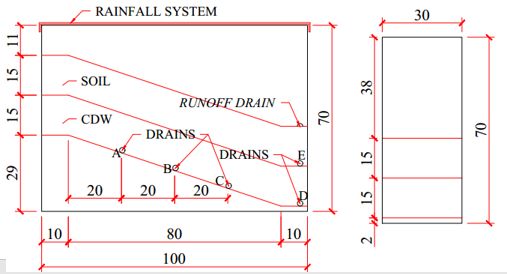
MATEC Web of Conferences 337, 04007 (2021)                                                         https://doi.org/10.1051/matecconf/202133704007
PanAm-UNSAT 2021

           Through this test, a granulometric contrast between
       both materials was indeed observed, which points to the
       possible use of both materials for a CB composition, in
       accordance with Barros [10] and Bizarreta & Campos [5].
       Nevertheless, the CDW also presented a considerable fine
       content (particles passing in mesh #200), which could
       partially damage the capillary barrier effect.
           The compaction results can be observed in Figure 6,
       for situations with and without material reuse. Results are
       consistent     with    other    results    presented    by
       Das & Sobhan [28] for the same material type
       (considering the USCS classification). Also, there was
       almost no change in the CWD curve due to the material
       reuse, however, the possibility that the compaction could
       change CDW grains granulometric distribution (due to its            Fig. 7. Soil–Water Characteristic Curve of soil and CDW.
       break) is not discarded and complementary analysis                  (T: volumetric moisture content; \: suction).
       (granulometry after compaction) would be required to
       verify this hypothesis.                                                 Despite that, the CWD also presents a considerable
                                                                           water retention capacity, i.e., the curve is slightly different
                                                                           from the sand ones, which was also observed by
                                                                           Bizarreta & Campos [5]. Possibly, this occurs due to the
                                                                           CDW particles microposority, which would demand more
                                                                           detailed studies about this aspect for posterior
                                                                           confirmation.
                                                                               In general, comparing the obtained results of this work
                                                                           with others of the literature ([5] and [30]), a huge
                                                                           variability in CDW characteristics was identified, which
                                                                           can be a limiting factor to this work proposition or to
                                                                           others works that aim the reuse/recycling of these wastes.

                                                                           3.2 Flume model

       Fig. 6. Compaction curves of soil and CDW. (w: moisture             The flume model tests indicated indeed the occurrence of
       content; wopt: optimum moisture content; Jd max: maximum dry        the capillary barrier effect between the soil and CDW.
       density).                                                           Through these tests, percolation velocities, permanency
                                                                           period of the flow in the materials interface (“CB period”)
           Regarding the grains specific mass (Gs) and the                 and the collected volume water by drains were measured,
       saturated permeability coefficient (ksat), the results can be       as the scheme shown in Figure 8.
       observed in Table 2. Permeability results evidence the
       difficulty in reaching low permeabilities for a soil with an
       80% compaction degree, characteristic that is required for
       its use in monolithic covers. High CDW permeability was
       also observed.
                       Table 2. Gs and ksat results.

                                              ksat_20ºC
                    Material       Gs
                                              (cm/s)
                       Soil        2,71      1,64E-04
                      CDW          2,70      1,62E-02

           Finally, regarding the soil-water characteristic curve
       (Figure 7), we can note that the soil has a bigger water
       retention capacity than the CWD, as expected, evidencing
       the suction materials contrast. This indicates the potential
       formation of a capillary barrier between both materials,            Fig. 8. Capillary barrier test.
       with their associated use [29].
                                                                              In Table 3, the permanency time of the flow in the
                                                                           materials interface before the water advance to the
                                                                           capillary block (CDW), column “BC (s)”, can be
                                                                           observed. Also, percolation velocity results are presented,

                                                                       5
MATEC Web of Conferences 337, 04007 (2021) https://doi.org/10.1051/matecconf/202133704007
PanAm-UNSAT 2021
as well as some parameters that were verified a posteriori caused the water accumulation on the surface, with
through the extraction of undisturbed samples (dry consequent runoff. The second drain with the higher
density, Jd, its respective compaction degree, CD, and collected water volumes was the D one (capillary block
field capacity, wfield). foot, CDW), which corresponds to the lower point of the
system. These results can be observed in better details in
Table 3. Flume model results. Table 4.
Perc. vel. (cm/s) BC (s) Soil CD Table 4. Drain collection results. (R: runoff drain).
Test-S0
Soil CDW (%)
E1-4,5% 9,29E-03 2,86E-03 178 83,8 Rain Drain collection (%)*
Test (mm)
E2-10,3% 1,43E-02 2,87E-03 179 82,2 R A B C D E
E3-17,3% 1,38E-02 7,24E-03 95 81,7 E1 210,7 83,8 --- 0,9 0,3 15,0 ---
(continuation...) E2 208,0 90,9 --- 0,3 --- 8,8 ---
Jd (kg/dm³) wfield (%) E3 121,4 44,2 9,1 7,0 10,7 28,4 0,6
Test-S0
Soil CDW Soil CDW
E1-4,5% 1,51 1,40 23,9 15,7 *Percentage regarding the total collected amount (drain sum).
Part of the water was retained in the system itself.
E2-10,3% 1,48 1,38 22,5 17,0
E3-17,3% 1,47 1,38 23,5 16,3 We can observe that the E3 test (S0=17,3%) presents a
different behavior from the others, with certain balance
The percolation velocities in the soil resulted in between the drain readings. A possible explanation for
similar values and the predicted 80% CD was confirmed. this fact is that water percolated faster in this test (as
Regarding the CDW, it is observed that as the initial previously discussed), due to the greater initial saturation
saturation degree increased, the percolation velocities also degree of CDW when compared to E1 and E2 tests. In
increased, which, as consequence, shortens the flow case of total CDW saturation, water volumes collected by
arrival period at the foot layer (this would represent the drains would be even greater, i.e., system percolation rates
wastes in real conditions – a landfill). The same depend on initial saturation of capillary block (greater
observation is valid for the permanency time of the flow moisture, lower permeability contrast between the
in the CB (bigger S0, lower time), which may indicate the materials). Besides that, it (E3) was the only test where
existence of a point, i.e., a CDW saturation value from the drains presented an adequate operation.
where the CB effect between the materials stop being The different rain volumes between the tests (due to
effective. the limitations in controlling the rain simulator, which
In addition, lateral flow measurements of soil layer depended on the distribution system flow rate) made the
were taken, which resulted in average 2,5E-02 cm/s and direct comparison of results unfeasible. For this reason,
throughout the test, it could be noted that the runoff drain the collect volumes in each drain were converted to rains
just started operating after the arriving of the laterally of 90mm (initial proposed value), considering a linear
flow under the drain. Also, during flow permanency in the relation. Thus, the contribution percentage of the drains
materials interface, the advance of lateral flow in the clay (A, B, C and D, which represent the volume that would
layer went on. enter the residues mass) were obtained, regarding a
Through samples taken from the flume model a 90 mm rainfall event. For E1 and E2 tests, the
posteriori, materials field capacity were estimated which contribution is zero and for the E3 test, the value was
resulted in 23,3% (Tcc|35%) for the soil and 16,3% 2,7%. These results are positive, once they demonstrate
(Tcc|23%) for the CDW. Both presented a good water that extremely rare events would be necessary for the flow
storage capacity, which corroborates with materials soil- to cross all the CB system proposed, given the conditions
water characteristic curve. A correspondent rain volume tested in the present work. Other authors as
value was calculated, this volume would be retained in the Krisdani et al. [31] and NG et al. [15] that also used
flume model layers (considering the adopted thickness in cohesive soils in the CB obtained similar results.
the present work and the initial materials moisture). An There is not a consensus or standard that indicates an
average value of 32,8mm was obtained for the soil and acceptable range of values for the percentage of rainfall
28,3 mm, 27,0 mm and 20,8 mm, for the CDW with S0 of that percolates into the residues mass [2], however,
4,5%, 10,3% and 17,3%, respectively. This is an Hauser [32] suggests a maximum value of 3% (annually).
interesting result once the CB system is capable of Hence, results of this work are satisfactory. Other authors
retaining by itself the rainfall events that are bigger than as Silva [33] and Oliveira & Braga [34] point that in
50mm, for the analyzed conditions. In a practical point of Brazil, this percentage reaches values up to 50%.
view, the materials are close to the atmosphere and, The rainfall percentage parameter that percolates into
therefore, they would be susceptible to other moisture the residues mass is one of biggest interest for the final
conditions due to possible successive rainfall occurrence cover landfill designs, because from this value it is
and its evaporation (moistening and drying cycles), what possible to determinate the produced leachate quantity
would give different results. (formulations in [35]), where the lower the values the
Regarding percolation monitoring through the drains, better, what could assist in the contingency of soil and
the biggest rainfall amount was collected by the runoff hydraulic bodies contamination in landfills surroundings,
drain, possibly because of the high rain intensity, which
6MATEC Web of Conferences 337, 04007 (2021) https://doi.org/10.1051/matecconf/202133704007
PanAm-UNSAT 2021
as well as economy in drainage systems and/or leachate percolation in capillary block (CDW) is even slower than
treatment or recirculation systems. in capillary layer (soil). These conditions favor the
percolation minimization of water into the residues mass
in this type of cover system.
3.2.1 Flume model limitations
Despite the research limitations, that came along with
The approach of this work consists in a non-standardized the experimental methodology that was applied, positive
experimental methodology and, therefore, during the tests results have been reached. The presented proposal is a
several limitations were identified, limitations that can be subject of interest because in addition to replacing a
improved for future researches involving flume models. substantial amount of natural material used in the final
The first limitation refers to the wooden plate of box landfills covers (the soil), it employs other material that is
bottom, the one over the sand, which molded the system widely available in urban centers (CDW), whose final
inclination: this element impermeabilization failed, which disposal is complex. Also, the amounts of generated CDW
caused both water absorption and its expansion, resulting in the cities in last years have been growing and this
in leaks under the CB system layers. For future tests, the material requires solutions to be reincorporated in the
wood could be replaced by a PVC plate or a similar industrial/construction sector.
material, that would not absorb water. Lastly, more realistic studies, considering the water
Another limitation was the adequate control of rainfall balance (evapotranspiration) in these type of cover
simulator flow rate, once the initial estimated rainfall systems would be interesting to a better understanding and
values did not match the values that were in fact supplied evaluation of this work proposal.
to the system. For future tests a possibility would be the
use of reservoirs with a pre-defined volume and pumps,
References
just as suggested by Almeida [12]. Other alternative
would be the use of a rotameter (flow meter) linked to the 1. ABRELPE. (2019). Panorama dos resíduos sólidos
supply system tap, for a constant control of the tap and, no Brasil 2019. Available in:
therefore, of the rainfall flow rate. . Acess: 28 sep. 2020.
probably the inadequate drain operation of some drains
2. R. M. Koerner & D.E. Daniel. (1997). Final covers
(for the extreme rainfall conditions, when water flow
for solid waste landfills and abandoned dumps.
reaches the capillary block foot). One explanation for this
ASCE.
problem is the low water level (movements in unsaturated
conditions) and the non-saturation condition of the 3. D. KovačIć. (1994). Materials for the final cover of
geotextile, which could form a CB itself above the drain. sanitary landfills. Rudarsko-geološko-naftni zbornik
For future researches, a suggestion would be to perform 6, 11-15.
an opening along the whole drain length (such as the one 4. F. G. Simon & W. W. Müller. (2004). Standard and
made for the runoff drain), and, added to that, its filling alternative landfill capping design in Germany.
with gravel, in order to make easier the water entry into Environmental Science & Policy 7, 277-290.
the element. doi:10.1016/j.envsci.2004.04.002
5. J. O. Bizarreta & T. P. Campos. (2017).
4 Conclusions Caracterização geotécnica de um RCD e uma argila
visando sua utilização como barreira capilar. In: E. L.
The results of this work indicate that the studied materials Cardozo. Geologia ambiental: Tecnologias para o
(soil from the region, CL-USCS, and the fine CDW desenvolvimento sustentável - vol. 2, 19-33. Ponta
fraction, SM) are compatible for the associated Grossa: Atena.
application in capillary barrier systems, with the use of the 6. R. R. Weil & N. C. Brady. (2017). The Nature and
soil as the capillary layer and of the CDW as the capillary Property of Soils. 15. ed. Harlow: Pearson.
block. Through the characterization tests the 7. M. Kämpf & H. Montenegro. (1997). On the
granulometric contrasts between the materials as well as performance of capillary barriers as landfill cover.
the water retention capacity (suction) contrasts could be Hydrology and Earth Systems Sciences 4, 925-929.
noted. Regarding the soil-water characteristic curve, it
was observed that the CDW has a considerable retention 8. M. Aubertin, E. Cifuentes, S. A. Apithy, B. Bussière,
capacity (bigger than the natural materials classified as J. Molson, R. P. Chapuis. (2009). Analyses of water
SM, which possibly occurs due to the particles porosity diversion along inclined covers with capillary barrier
that form the CDW (for example, ceramic/bricks or effects. Can. Geotech. J. 46, 1146-1164.
cement residues). doi:10.1139/T09-050
The flume model tests indicated that there is an initial 9. F.R. Harnas, H. Rahardjo, E. C. Leong, J. Y. Wang.
CDW saturation value from where the CB mechanism (2014). Experimental study on dual capilary barrier
between the materials is no longer effective (in the case of using recycled asphalt pavement materials. Can.
this work, this value would be between 10,3% and Geotech. J. 51, 1165-1177. doi:
17,3%). In other words, CB system operation depends on dx.doi.org/10.1139/cgj-2013-0432
initial saturation degree of capillary block. Another 10. M.C. Barros. (2005). Avaliação de um resíduo da
important observation is that after CB break, vertical construção civil beneficiado como material
7MATEC Web of Conferences 337, 04007 (2021) https://doi.org/10.1051/matecconf/202133704007
PanAm-UNSAT 2021
alternativo para sistema de cobertura. 96 p. 24. SIMEPAR – Sistema Meteorológico Do Paraná
Dissertation (Civil Engineering Master)–Instituto (2019). Dados pluviométricos de estação em Foz do
Alberto Luiz Coimbra de Pós-Graduação e Pesquisa Iguaçu no intervalo de 31/12/1997 a 31/12/2018.
de Engenharia, Universidade Federal do Rio de 25. J. L. B. Moreira. (2002). Estudo da Distribuição
Janeiro, Rio de Janeiro. espacial das Chuvas em Belo Horizonte e em seu
11. M. Kämpf, T. Holfelder, H. Montenegro. (2003). entorno. Dissertation (Master). UFMG, Belo
Indentificacion and parameterization of flow Horizonte.
processes in artificial capillary barriers. Water 26. M.D. Costa, M. O. H. Mariano, L. B. Araujo, J. F. T.
Resources Research 39:10, 1-9. doi: Jucá. (2018). Estudos laboratoriais para avalização do
10.1029/2002WR001860 desempenho de camadas de cobertura de aterros
12. J. Almeida. (2011). Estudo do comportamento de sanitários em relação à redução de emissões de gases
barreira capilar em aterros de resíduos. 152 p. e infiltrações. Eng Sanit Ambient 23:1, 77-90. doi:
Dissertation (Civil Engineering Master)–Instituto 10.1590/S1413-41522018160393
Alberto Luiz Coimbra de Pós-Graduação e Pesquisa 27. F. J. Maciel & J. F. T. Jucá. (2011). Evaluation of
de Engenharia, Universidade Federal do Rio de landfill gas production and emissions in a MSW
Janeiro, Rio de Janeiro. large-scale experimental cell in Brazil. Waste
13. R. L. S. Izzo, C. F. Mahler, L. Rose. (2013). Barreira Management 31, 966-977. doi:
capilar construída com resíduo pré-tratado mecânica 10.1016/j.wasman.2011.01.030
e biologicamente. Eng Sanit e Ambient 18:4, 303-312. 28. B. M. Das & K. Sobhan. (2017). Fundamentos de
14. T. L. T. Zhan, H. Li, G. W. Jia, Y. M Chen, D. G. Engenharia Geotécnica. 8. ed. São Paulo: Cengage
Fredlund. (2014). Physical and numerical study of Learning.
lateral diversion by three-layer inclined capillary 29. M. V. Khire, H. Benson, P. J. Bosscher. (2000).
barrier covers under humid climatic conditions. Can. Capillary barriers: design variables and water
Geotech. J. 51, 1438-1448. doi: balance. Journal of Geotechnical and
dx.doi.org/10.1139/cgj-2013-0449 Geoenvironmental Engineering 126:8, 695-708.
15. C.W. Ng, J. Liu, R. Chen, J. Xu. (2015). Physical and 30. M. A. B. Silva Junior. (2010). Avaliação da
numerical modeling of an inclined three-layer potencialidade dos RCD’s visando sua aplicação em
(silt/gravelly sand/clay) capillary barrier cover cobertura final de aterros. Undergraduate thesis
system under extreme rainfall. Waste Management. (Civil Engineering) - Escola Politécnica de
doi: http://dx.doi.org/10.1016/j.wasman.2014.12.013 Pernambuco, UFPE.
16. ABNT. (2017). NBR 16605: Cimento Portland e 31. H. Krisdani, H. Rahardjo, E. C. Leong. (2005).
outros materiais em pó – Determinação da massa Behaviour of capillary barrier system constructed
específica. Rio de Janeiro. using residual soil. Waste Containment and
17. ABNT. (2016). NBR 7181: Solo - Análise Remediation. 1-15.
granulométrica. Rio de Janeiro. 32. V. L. Hauser. (2009). Evapotranspiration Covers for
18. ABNT. (2016). NBR 7182: Solo - Ensaio de Landfills and Waste Sites. Boca Raton: Taylor &
compactação. Rio de Janeiro. Francis Group.
19. ABNT. (2000). NBR 14545: Solo - Determinação do 33. K. T. Silva. (2016). Projeto de um aterro sanitário de
coeficiente de permeabilidade de solos argilosos a pequeno porte. 81 p. Design (Civil Engineering) -
carga variável. Rio de Janeiro. Escola Politécnica, UFRJ.
20. ABNT. (1995). NBR 13292: Determinação do 34. R. F. Oliveira & R. M. Q. L. Braga. (2017). Sistema
coeficiente de solos granulares à carga constante. Rio de cobertura final de um aterro sanitário para a RMB
de Janeiro. de Belém-PA com emprego de resíduos da
21. L. F. S. Villar. (2002). Estudo do adensamento e construção civil. Revista Gestão e Sustentabilidade
ressecamento de resíduos de mineração e Ambiental, Florianópolis 6:3, 573-596. doi:
processamento de bauxita. 461 p. Thesis (Civil 10.19177/rgsa.v6e32017573-596
Engineering Doctor degree)-Programa de Pós- 35. X. Qian, R. M. Koerner, D. H. Gray. (2002).
Graduação em Engenharia Civil, PUC-Rio, Rio de Geotechnical Aspects of Landfill Design and
Janeiro. Construction. New Jersey: Prentice Hall.
22. J. C. O. Bizarreta. (2009). Avaliação do potencial de
uso de um resíduo da indústria de papel em sistemas
de barreiras capilares. 108 p. Dissertation (Civil
Engineering Master)-Departamento de Engenharia
Civil, PUC-Rio, Rio de Janeiro.
23. ABNT. (2016). NBR 6457: Amostras de solo -
Preparação para ensaios de compactação e ensaios de
caracterização. Rio de Janeiro.
8You can also read