Survey on Low-Cost Underwater Sensor Networks: From Niche Applications to Everyday Use
←
→
Page content transcription
If your browser does not render page correctly, please read the page content below
Journal of
             Marine Science
             and Engineering

Article
Survey on Low-Cost Underwater Sensor Networks: From Niche
Applications to Everyday Use
Filippo Campagnaro 1, * , Fabian Steinmetz 2                     and Bernd-Christian Renner 2

                                         1   Department of Information Engineering, University of Padova, Via Gradenigo 6b, 35131 Padova, Italy
                                         2   Institute for Autonomous Cyber-Physical Systems, Hamburg University of Technology, Harburger
                                             Schloßstraße 28, 21079 Hamburg, Germany
                                         *   Correspondence: campagn1@dei.unipd.it; Tel.: +39-049-827-7778

                                         Abstract: Traditionally, underwater acoustic modems and positioning systems were developed for
                                         military and Oil & Gas industries, that require deep water deployments and extremely reliable
                                         systems, focusing on high power expensive systems and leaving the use of low-cost devices only
                                         attractive for academic studies. Conversely, recent developments of low-cost unmanned vehicles,
                                         such as remotely operated vehicles (ROVs) and autonomous underwater vehicles (AUVs), suitable for
                                         shallow water coastal missions, and the need of sensors network deployments for measuring water
                                         quality and studying the effect of climate change in coastal areas, called to the need of low-cost and
                                         low-power acoustic modems and positioning systems that are gaining more and more momentum to
                                         date. The use of these devices can enable a wide set of applications, often based on low-cost AUV
                                         swarm formations, where an acoustic link between the vehicles is required to coordinate the mission,
                                         perform the maneuvers, and maintain the formation along the time. Moreover, they can make
                                         environmental wireless sensor deployment cost effective by substituting wired systems. Underwater
                                         positioning systems, usually used in large-scale operations, can be finally applied to small-scale
                                         application thanks to the reduction in costs, at the price of a lower transmission and positioning
                                         range and precision. While in open-sea application this performance reduction is a huge limitation,
                                         in river, lagoon, port and lake deployments this is not an issue, given that the extremely shallow
                                         water and the presence of many obstacles would deteriorate the acoustic signal anyway, not allowing
                                         long range transmissions even with expensive and sophisticated acoustic devices. In this paper, we
                                         review the recent developments of low-cost and low-power acoustic communication and positioning
Citation: Campagnaro, F.; Steinmetz,
                                         systems, both analyzing University prototypes and new commercial devices available in the market,
F.; Renner, B.-C. Survey on Low-Cost
                                         identifying advantages and limitations of these devices, and we describe potential new applications
Underwater Sensor Networks: From
                                         that can be enabled by these systems.
Niche Applications to Everyday Use.
J. Mar. Sci. Eng. 2023, 11, 125.
https://doi.org/10.3390/jmse11010125
                                         Keywords: underwater acoustic networks; underwater acoustic positioning system; underwater
                                         low-cost assets; underwater monitoring; review
Academic Editor: Christos Tsabaris

Received: 18 November 2022
Revised: 22 December 2022
Accepted: 22 December 2022               1. Introduction
Published: 6 January 2023                     The high power consumption and the high cost of traditional commercial acoustic
                                         modems [1–3] and positioning systems [4–6], typically used in military and offshore deep
                                         water deployments, makes them unaffordable for many civil applications, such as de-
                                         velopment of underwater internet of things (UIoT) sensor networks for monitoring the
Copyright: © 2023 by the authors.
                                         water quality of bathing and aquaculture sites [7] and ports [8], and for observing the
Licensee MDPI, Basel, Switzerland.
                                         biodiversity of a certain area. In addition, their use in low-cost remotely operated vehicles
This article is an open access article
distributed under the terms and
                                         (ROVs) and autonomous underwater vehicles (AUVs) is prohibitive due to the fact that
conditions of the Creative Commons
                                         the price of a low-cost underwater vehicle, such as the BlueROV [9] (that costs less than
Attribution (CC BY) license (https://
                                         5000 EUR), is approximately half of the cost of modems equipped with ultra-short baseline
creativecommons.org/licenses/by/         acoustic positioning systems (USBLs). The recent availability of these low-cost unmanned
4.0/).                                   vehicles [9,10] and the introduction of new sensor technologies applicable to smart ports [8]

J. Mar. Sci. Eng. 2023, 11, 125. https://doi.org/10.3390/jmse11010125                                          https://www.mdpi.com/journal/jmse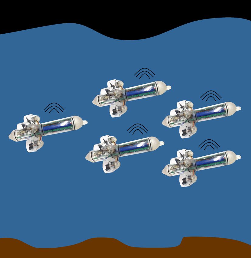
J. Mar. Sci. Eng. 2023, 11, 125 2 of 25
and aquaculture sites [7], called for new developments of both industries [11] and research
institutes [12] that, in the last five years, focused their effort on realizing low-cost and
low-power acoustic modems and positioning systems, rather than following the previous
research trend of further increasing transmission range, datarate and ranging accuracy.
In fact, the requirements of the aforementioned applications in terms of communication
range and datarate are not as stringent as the one needed for surveillance and offshore
applications, and also the maximum depth of the deployment in this coastal applications is
typically a few tens of meters, instead of the several hundreds of meters or even several
kilometers deployments used in offshore applications: this enables the possibility to use
low-depth rated casing and therefore reducing the cost of development and materials.
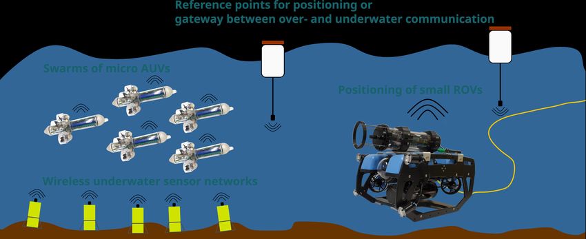
These new coastal civil applications (Figure 1) require simple and affordable devices that
can be powered with small batteries, such as smartphone power-banks. New products
are now available, all characterized by a cost of less than 1000 EUR, a maximum power
consumption of approximately 1 W, in transmission, and 100 mW in reception, and able
to transmit and perform ranging operations up to a few hundreds meters at a datarate
between a few tens [11,13,14] and a few hundreds [12,15,16] of bits per second.
Figure 1. New applications enabled by low-cost underwater modems and positioning systems.
Abbreviations: autonomous underwater vehicle (AUV), remotely operated vehicle (ROV).
The main contribution of this paper is the complete and updated review of these
affordable devices, their comparison with legacy acoustic modems, and the discussion
of potential applications enabled by low-cost acoustic modems and positioning systems.
Most of the previous survey papers focus on acoustic communication, networking and
positioning for offshore applications e.g., [17–19]. The authors in [20,21] provide extensive
reviews of acoustic underwater modems. Although in both works the authors mentioned
small-scale acoustic modems for low-cost applications, recent developments have not been
discussed, as the survey presented in [20] reviews articles up to 2015 and the one in [21]
articles up to 2018. Underwater positioning systems are discussed in [22] for confined
environments, e.g., industrial tanks or nuclear storage facilities. In [23,24] underwater
navigation and localization systems are analyzed. These surveys provide an overview of
different systems and acoustic positioning is presented very briefly.
This article investigates whether or not in the near future underwater networks can be
used in civil applications for everyday use. To answer this question a complete review of
the state-of-the-art of low-cost acoustic modems and their potential applications is carried
out. The information inserted in this review is mainly based on direct experience of the
authors, given that both the Hamburg University of Technology and the University of
Padova developed prototypes of low-cost acoustic modems. This development required
the authors to be constantly updated on the most novel research trends related to this
argument, making them becoming quite experienced in the field of low-cost acoustic
modems. In fact, the literature survey performed by the authors is based not only on a web
research using the most common research engines, where key words such as “low-cost
acoustic modems” have been searched, but also on the knowledge gained by the authors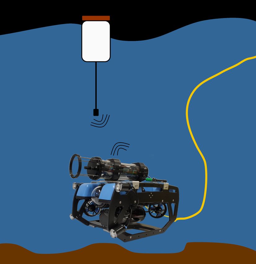
J. Mar. Sci. Eng. 2023, 11, 125 3 of 25
attending tens of international conferences and workshops on underwater communication
in the last five years, exploiting these events to exchange ideas and information with many
research fellows operating in this area. In sum, we added 123 references to this survey.
The references include 37 internet links and 86 scientific papers. 45 papers cover acoustic
modems and positioning systems. The other 41 papers examine applications and previous
surveys. Figure 2 depicts the distribution of publication dates for all papers and those
with acoustic modems and positioning systems. More than 51% of the cited papers were
published during the last 5 years.
12
modem and positioning
10 all papers
no. of citations
8
6
4
2
0
5
6
7
8
9
0
1
2
3
4
5
6
7
8
9
0
1
2
00
00
00
00
00
01
01
01
01
01
01
01
01
01
01
02
02
02
2
2
2
2
2
2
2
2
2
2
2
2
2
2
2
2
2
2
year
Figure 2. Cited scientific papers compared to the publication date. In sum, 86 scientific papers are
discussed in this paper. 45 papers cover acoustic modems and positioning systems and 41 papers
examine applications and previous surveys.
This paper is structured as follows. Section 2 presents a review of the currently
available low-cost acoustic modems, while newly available acoustic positioning systems
are discussed in Section 3. Section 4 presents new potential applications enabled by these
new acoustic communication and positioning devices in light of the recent development in
underwater robotics, sensor and navigation systems. Moreover, the same section presents
the limitations of the current technology and tries to identify what is still missing to bring
underwater networks to the mainstream. Finally, Section 5 draws our concluding remarks.
2. Underwater Acoustic Modems
In this section, after introducing the various underwater communication technologies
(Section 2.1), we review the state of art of acoustic modems, starting from a discussion of
the acoustic modem used in legacy offshore and military operations (Section 2.2) and then
reviewing low-cost acoustic modems for UIoT (Section 2.3) applications.
2.1. Introduction to Underwater Wireless Communication
Four underwater wireless communication technologies are available to date, namely
underwater electromagnetic radio frequency (RF), magneto-inductive, optical and acoustic
communication [25]. Given the high attenuation of electromagnetic signals, especially in
salty water, regular WiFi, cellular and satellite technologies cannot be used to perform
long range transmissions underwater. Very Low Frequency (VLF) and Extremely Low
frequency (ELF) RF antennas were used during the Cold War to enable communication
from an over water base station to submarines, transmitting with very low bitrate and with
a very high-power consumption. While VLF deployments allow communication up to
a depth of 20 m below the sea surface, ELF systems have global coverage but require an
antenna with a size of tens of kilometers and to irradiate 2 W of power they require a power
consumption of 1 MW [26]. Given that ELF and VLF installations are very expensive, only
a few countries in the world had those type of systems: almost all of them are currently
dismissed. Conversely, today a few small high-rate (order of a few Mbps) low range (up
to 1–2 m) commercial RF modems are used in AUV docking stations and for a few other
specific applications [27]. Magneto-inductive modems, instead, can reach a distance up to
a few tens of meters and a bitrate of a few kbps [25]: their main advantage is the possibility
to cross the water-to-air boundary, but their high transmission power may affect marine life.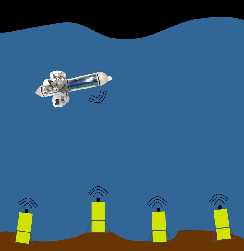
J. Mar. Sci. Eng. 2023, 11, 125                                                                                                                                           4 of 25

                                                     Able to cover the same distance, but also to provide a higher rate of a few Mbps, optical
                                                     modems are currently the preferred communication devices for underwater broadband
                                                     short-range links [28]: while light emitting diodes based transmitters can provide a rate
                                                     of a few Mbps at a range of tens of meters, laser-based systems can achieve a higher
                                                     distance and rate, but transmitter and receiver have to be perfectly aligned. Currently,
                                                     acoustic modems are the only devices able to establish long underwater links, up to a
                                                     distance of tens of kilometers [3]. Despite their low bitrate imposed by the low bandwidth
                                                     available in the acoustic channel, they are the mostly used communication technologies,
                                                     with several industrial and research devices being developed in the last decades: for this
                                                     reason this paper reviews the state of art of underwater acoustic communication systems.
                                                     The four aforementioned communication technologies are summarized in Figure 3, where
                                                     we can clearly observe that optical communication outperforms all other technologies
                                                     for short range links, while acoustic is the only technology able to support long range
                                                     communication. Still, the fact that magneto inductive and RF are not affected by turbidity,
                                                     multipath, sunlight and shipping noise, make them valuable alternatives when the channel
                                                     conditions are not favorable for acoustic and optical communication.
                                   1010
                                                                                                 3 Gbps        Optical:
                                                                                                 @ 10 m        Enables high speed links, require alignment
                                                                                                               between transmitter and receiver, affected
                                                        100 Mbps                                               by ambient light noise and water turbidity
                                   108
                                                        @ 5 cm
                                                                                                                10 Mbps                Acoustic:
                                                                                                                @ 80 m                 Enables long-range low-rate
                                                                              1 Mbps                               1 Mbps              links, the most mature tech-
                data rate in bps

                                   106                                                                                                 nology, affected by multi-
                                                                              @ 1m                                 @ 120 m             path, Doppler, acoustic noise,
                                          Radio Frequency:                                                            100 kbps         changes of temperature, may
                                          Omnidirectional, affected                                                   @ 200 m          affect marine mammals
                                          by water salinity and                                 8 kbps
                                   104    electromagnetic noise,
                                                                                                @ 10 m
                                          strongly attenuated by wa-
                                                                                              2 kbps   1 kbps                                          1 kbps
                                          ter, mainly used in dock-
                                          ing stations, able to cross                         @ 8m     @ 40 m                                          @ 10 km
                                          water-to-air boundary
                                   102                                                                                      40 bps
                                                                        Magneto Inductive:                                                              150 bps
                                                                        Omnidirectional, high power consumption,            @ 400 m                     @ 30 km
                                                                        may affect marine life, affected by electromag-
                                                                        netic noise, able to cross water-to-air boundary
                                   100
                                      10−2              10−1            100                101                102              103               104                105
                                                                                                 range in m

                                                      Figure 3. Comparison between underwater communication technologies (based on [27]).

                                                      2.2. Acoustic Modems for Offshore Applications
                                                           Underwater sensor networks are typically used in military and offshore applications.
                                                     Their main requirement is to provide the coverage of a wide area where an asset needs
                                                     to be maintained under control. In military scenarios, for instance, the goal is to perform
                                                     surveillance of a strategic site, usually located near the coasts, identifying whether enemies
                                                     are approaching that area. In Oil and Gas applications, instead, AUVs are often used to
                                                     monitor pipelines and Oil stations: a network of submerged nodes helps maintaining the
                                                     control of the vehicles for the whole mission duration.
                                                           Depending on the expected conditions and the user needs, there is a wide set of
                                                     acoustic modems for offshore and military applications in the market, that can be employed
                                                     in a variety of specific scenarios.
                                                           For example, to achieve a communication range of more than 4 km, modems with a car-
                                                     rier frequency below 12 kHz are usually used: in this category we can mention the Benthos
                                                     ATM 960 modem operating in the low frequency (LF) band [3], the EvoLogics S2C 7/17 [1]
                                                     modem, and the Develogic HAM node [2]. The transducers of most of these devices can
                                                     be customized to the geometry of the channel and also the modem bitrate can be adapted
                                                     accordingly. For this reason, all LF modems can achieve a communication rate up to a few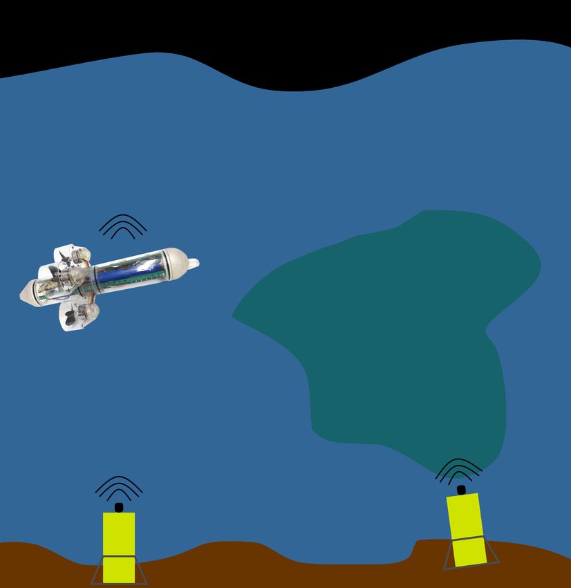
J. Mar. Sci. Eng. 2023, 11, 125                                                                                           5 of 25

                                  kilobits per second in a vertical link in deep water, where the multipath is negligible, while
                                  in a horizontal link in very shallow water they can reach a maximum rate of few hundreds
                                  of bits per second. These modems are the mostly used in military applications, where nodes
                                  are often organized in barrier to identify if an intruder is approaching a protected area, and
                                  the goal is to cover the widest area with the minimum number of nodes [29]. Also, the first
                                  version of the NATO JANUS standard [30], that enables interoperability between modems
                                  of different manufacturers, focuses on LF acoustic communications, and so does the first
                                  version of the NATO underwater telephone and telegraph [31].
                                        medium frequency (MF) modems, instead, are the most used for communication
                                  ranges from 1 to 3 km, as they can cover this range by providing a bitrate higher than LF
                                  modems. In this paper, we classify as MF all modems with a carrier frequency between 20
                                  and 35 kHz. All the aforementioned manufacturers that produce LF devices also develop
                                  MF acoustic modems. In addition to them, other companies also supply commercial off-the-
                                  shelf products in this range, such as the Popoto Modem [32], the Applicon Seamodem [33],
                                  the Sonardyne 6G [34], the DSPComm Aquacomm Gen2 [15], the SubNero [35] and the
                                  Blueprint Subsea [36] acoustic modem. These modems are the most used onboard AUVs
                                  and inspection class ROVs, as they are smaller and lighter than LF modems, significantly
                                  simplifying their integration in unmanned vehicles, still providing a communication range
                                  of a few kilometers. In addition, using ultrasounds for the transmission and the reception,
                                  they are less affected by acoustic noise caused by vessel propellers [37]. For this reason, in
                                  the new military scenarios, multimodal networks composed of both LF and MF acoustic
                                  modems are often considered [38,39], where the MF modem is used to communicate
                                  between nodes in the same barrier and with AUVs, and the LF communication system is
                                  used to communicate between nodes in different barriers. Various manufacturers [31,40]
                                  and research institutes [41,42] develop acoustic modems in the LF and MF band for their
                                  national defence, confirming the interest of the Navy in these devices.
                                        In the context of offshore and military applications, high frequency (HF) acoustic
                                  modems (with a carrier frequency higher than 35 kHz) are rarely used, due to their short
                                  range, that is typically below 500 m. Although their high throughput (of about a few tens of
                                  kbps) can support interesting applications, such as quasi-realtime underwater low-quality
                                  video streaming [43,44], their short range makes their use very limited in coast surveillance
                                  scenario or deep water offshore applications. In fact, in this context they can only be used
                                  onboard AUVs that use MF or LF modems to coordinate their mission, and switch to HF
                                  when approaching a submerged node or a docking station to download a large quantity of
                                  data in a short time. Despite this data gathering (or data muling) application is of interest
                                  in these scenarios, there is a factor that need to be considered before deciding to adopt HF
                                  communication in this context [27]. Indeed, if an AUV approaches another submerged
                                  node, also other communication systems may be used. Specifically, for distances below
                                  50 m optical and electromagnetic modems can provide a very high throughput (up to a few
                                  Mbps) and are often preferred to HF modems [27]. A few companies supply HF acoustic
                                  modems for offshore applications. LinkQuest UWM220 [45] uses a carrier frequency of
                                  70 kHz to achieve a datarate up to 19 kbps at a range of up to 1 km. Evologics [1] provides
                                  two high-power HF modems, one for horizontal and one for vertical communication, with
                                  a carrier frequency between 50 kHz and 60 kHz, able to transmit up to 30 kbps at a range of
                                  1 km. They also supply a very high speed modem that uses a carrier frequency of 150 kHz
                                  and can transmit with a datarate of 60 kbps up to a range of 300 m. The latter has been used
                                  during an academic study in [43] to transmit a low quality video stream in quasi realtime.
                                  Other studies performed by Universities focus on HF acoustic communication. The SEANet
                                  modem [46], for instance, is designed to achieve a bitrate of more than 500 kbps at a range
                                  of a few tens of meters, using a carrier frequency of 500 kHz and a bandwidth of 600 kHz.
                                  The authors in [44] developed a multiple-input multiple-output (MIMO) acoustic modem
                                  able live stream a 200 kbps video acquired with a BlueROV to the operator, using the
                                  1–180 kHz band. The modem is designed to transmit up to a distance of a few tens of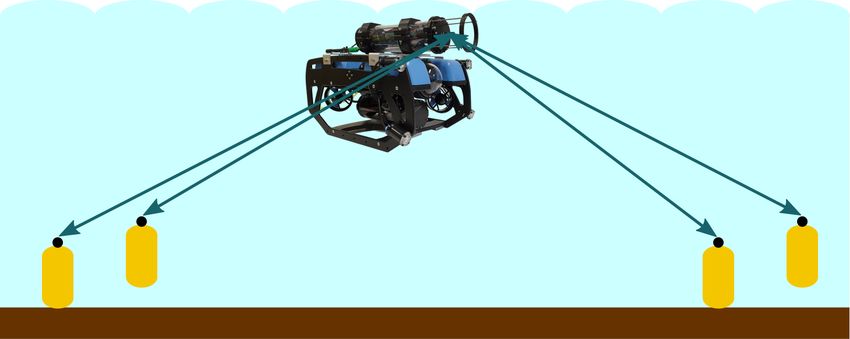
J. Mar. Sci. Eng. 2023, 11, 125                                                                                           6 of 25

                                  meters. Finally, the Hermes modem [47] can achieve a distance of 100 m and a throughput
                                  of 80 kbps, using a frequency band from 260 kHz to 380 kHz.

                                  2.3. Low-Cost Acoustic Modems
                                        In the LF and MF domain, some universities and civil research institutes developed
                                  low-cost low-power modems for medium and short range (few hundreds of meters) low-
                                  rate (few hundreds of bits per second) UIoT applications [48–52], by employing low-cost
                                  narrowband transducers.
                                        The design of one of the first low-cost acoustic modem is presented in [48], where all
                                  data processing was computed with a PC, and the authors used a simple PC microphone as
                                  a receiver and regular PC speakers as transmitter. They waterproofed the components with
                                  elastic membranes and managed to transmit a 24 bps frequency shift keying (FSK) signal
                                  up to a distance of 17 m using the frequencies between 1000 Hz and 2000 Hz. Similarly,
                                  the authors in [49] developed an FSK modem performing all signal processing in a PC
                                  with GNU RADIO, and developing their own do-it-yourself hydrophone composed of
                                  eight car-audio piezoelectric-tweeters (with the cost of 0.50 EUR each) waterproofed with a
                                  plastic container filled with vegetable oil. They managed to transmit with a rate of 100 to
                                  500 bps over a distance of up to 6 m. A very small LF modem specifically developed for
                                  micro AUVs is presented in [53]. This modem uses direct sequence spread spectrum (DSSS)
                                  modulation with a central frequency of 12.5 kHz and a bandwidth of 3 kHz, obtaining a
                                  bitrate of 55 bps up to a distance of 200 m.
                                        In the FPGA-based acoustic modem developed by University of California San Diego
                                  (UCSD) [51], the authors managed to avoid purchasing expensive underwater transducers
                                  by encapsulating in a potting compound a simple and low-cost piezoelectric transducer.
                                  They achieved a bitrate of 200 bps up to a range of 350 m transmitting in the 32–38 kHz band
                                  with a transmission power of 40 W. Although this modem uses a high power transmitter, its
                                  design inspired more recent works where other scientists developed their own underwater
                                  transducer. In [50], for instance, they introduce the concept of a surface receiver consisting
                                  of a hydrophone plugged into a standard sound card (with sampling frequency of 44.1 kHz
                                  or 48 kHz) of a mobile device such as a smart phone or tablet. They prove the possibility
                                  to transmit up to a range of 100 m transmitting with very low power and with a bitrate
                                  between 25 and 375 bps in the 8–16 kHz band, using a very low-cost hydrophone and chirp
                                  waveform. Using a similar waveform, the low-power Nanomodem [52] (and its newer
                                  version number 3 [54]) developed by the University of Newcastle, operates in the 24–28 kHz
                                  band, achieving a datarate of 40 bps within a surprising range of 2 km, despite the very
                                  low transmission power (168 dB re 1 µPa @ 1 m). The same research group also developed
                                  the Seatrac miniature acoustic modem [55] and USBL, that uses DSSS and operates in the
                                  ultrasonic 24–32 kHz band, achieving a throughput up to 1.4 kbps at a range of 1.5 km, with
                                  a transmission power of 176 dB re 1 µPa @ 1 m. It is designed to support communication
                                  and positioning between divers and ROVs and, despite it is a more complex system and
                                  uses a transmission power higher than the other modems discussed so far, its deserves
                                  to be mentioned in this context as its licence has been provided not only to Blueprint
                                  Subsea, that commercializes the USBL as it is, but also to Succorfish, that developed the
                                  SC4X portable integrated acoustic, iridium and GSM diver communications system [56], a
                                  low-power modem used to enable diver to diver and diver to surface communication with
                                  a datarate of 463 bps. The acoustic module installed in the latter does not uses USBL and
                                  has a maximum transmission power of only 168 dB re 1 µPa @ 1 m (like the Nanomodem),
                                  with significant reduction in development costs.
                                        A low-cost modem developed by the Tianjin and the Guilin Universities, China, based
                                  on the embedded system STM32H743 that uses single and multi carrier MFSK schemes has
                                  been presented in [57]. The modem can achieve a distance of 5 km with a bitrate of 125 bps,
                                  and of 2.5 km with a bitrate of 1 kbps, and operates in the 20–30 kHz band.
                                        Some commercial low-cost LF and MF acoustic modems (with a price of less than
                                  2 kEUR) are also available off-the-shelf. For instance, the modem launched by DSP-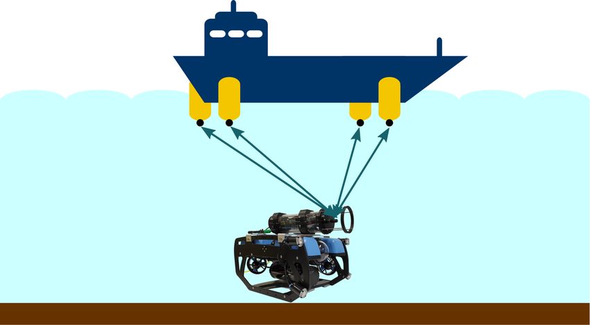
J. Mar. Sci. Eng. 2023, 11, 125                                                                                            7 of 25

                                  Comm [15] costs about 1 kEUR, uses the 16–30 kHz band, has a maximum transmission
                                  rate of 100 bps, and a nominal range of 500 m. With the same range, the Micron Data
                                  Modem developed by Tritech [13] is a low power compact modem with a maximum
                                  data rate of 40 bps and operates in the 20–28 kHz band. Its transmission power is up
                                  to 169 dB re 1 µPa @ 1 m and weighs less than 250 g. This modem is a commercial ver-
                                  sion of the aforementioned Nanomodem [52] designed by the Newcastle University, that
                                  gave Tritech its licence to produce the Micron Modem. DiveNET, a company that mainly
                                  produces communication and localization equipment for divers, supplies Sealink [58], an
                                  affordable and low power acoustic modem that provides either a range up to 8 km at a
                                  datarate of 80 bps using the 5–15 kHz band (models C and S) or, with a more compact
                                  design and a lower transmission power, a range of 1 km at a datarate of 78 bps using
                                  the 15–30 kHz band. Subnero [35], in addition to its high power and high depth-rated
                                  devices for industrial applications, it supplies a research edition software-defined-modem
                                  (WNC-M25MRS3) operating in the 20–32 kHz band and able to transmit up to 15 kbps at
                                  a maximum range of 1 km, with a source level of 175 dB re 1 µPa @ 1 m. Based on our
                                  knowledge, its price exceeds the one of the other low-cost commercial modems listed in
                                  this section, but is still less than half the cost of the modems used in offshore applications.
                                  Popoto Modem [32], in addition to solutions for offshore applications, also provides a series
                                  of low-rated and low-power modems with an affordable price of less than 2500 EUR. These
                                  modems use the 20–40 kHz band and achieve datarates up to 10 kbps at a typical range
                                  between 1 and 2 km. The AppliCon SeaModem [33] is commercially available as well: the
                                  modem uses FSK to transmit up to 2 kbps within a range up to 400 m. The modem uses a
                                  central frequency of 30 kHz and a bandwidth of 10 kHz.
                                        Also, affordable HF acoustic modems have been developed by both research insti-
                                  tutes [12,16,59,60] and companies [11,14].
                                        The very small ahoi modem [12] has a total component costs of less than 600 EUR, in-
                                  cluding an off-the-shelf transducer (400 EUR), microprocessor and the transceiver board de-
                                  veloped in house (200 EUR). It uses a very low transmission power of 160 dB re 1 µPa @ 1 m
                                  and the frequency band of 50 kHz to 75 kHz, achieving a throughput of 260 bps (default
                                  net rate, that can be increased up to 4.7 kbps in good channel conditions) and a range up to
                                  200 m in very shallow water, thanks to a robust frequency hopping (FH) FSK modulation.
                                  The recently-developed MODA modem [60] uses all off-the-shelf hardware components, in-
                                  cluding a Raspberry PI4 as a processing unit, a high quality 192 kHz audio DAQ Raspberry
                                  HAT, an audio amplifier for transmission, an hydrophone preamplifier in reception and
                                  two transducers, one for transmitting and one for receiving. The cost of all the components
                                  is 1000 EUR per modem: this price can be lowered significantly (of about 400 EUR) if a
                                  tx/rx switch is used instead of a second transducer. Optionally, the modem is designed to
                                  perform one way time travel ranging by relying in precise clocks such as oven-controlled
                                  crystal oscillator, that are more affordable than atomic clocks. The modem uses a carrier
                                  frequency of 50 kHz, a bandwidth of 20 kHz, and it is still under evaluation. For this reason
                                  the performance figures are not available at the moment: preliminary results have shown
                                  that it can perform reliable transmissions with a bitrate of 1 kbps at a distance of 80 m.
                                        The low-cost modem recently developed by the Xiamen University [61], China, oper-
                                  ates in the 35–45 kHz frequency band, and is able to achieve 500 m with a bitrate of a few
                                  hundred of bits per second using FH-MFSK. The total cost of components is approximately
                                  500 EUR and the maximum power consumption, when transmitting, less than 6 W. The
                                  micro-modem developed by the Gangneung-Wonju National University (South Korea) has
                                  a maximum consuming power of 8 W and transmits an BPSK signal using a frequency of
                                  70 kHz [62], reaching a maximum distance of a few hundred meters and a transmission rate
                                  that ranges between 200 bps and 5 kbps. The ITACA modem [16] provides transmission
                                  of digital data using coherent-FSK at rates of 1 kbps with an 85 kHz carrier frequency:
                                  the authors managed to transmit up to 240 m with a transmission power consumption of
                                  only 0.1 W. It uses a precise real-time-clock to perform coherent demodulation and to use
                                  a TDMA MAC scheme. It uses low-cost transducers (with a cost of about 100 EUR each)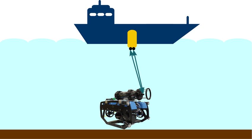
J. Mar. Sci. Eng. 2023, 11, 125                                                                                            8 of 25

                                  usually employed in low-cost echosounder applications, hence significantly reducing the
                                  hardware cost.
                                        Using a carrier frequency of 40 kHz, the FSK ultrasonic modem presented in [59]
                                  uses a very low-cost waterproof ultrasonic transducer typically used in the automotive
                                  industry for measuring the distance from the car and the closest obstacle. All processing
                                  is performed with an Arduino, and from a pool test the authors managed to perform
                                  error-free transmissions with a bitrate of 1.2 kbps up to a range of 1.5 m. The researchers
                                  from the Florida Altantic University (FAU) [63] recently developed a low-cost HF modem
                                  prototype with a transmission power of 5 W that, using FH-FSK is able to reach 50 m with
                                  a bitrate of 100 bps in the 100–150 kHz frequency band.
                                        Two commercial HF acoustic modems are avaliable off-the-shelf [11,14]. The low-cost
                                  Desert Star SAM-1 modem [14] uses either the 34–48 kHz band or the 65–75 kHz band,
                                  has a bitrate of a few tens of bits per second and a typical range of 250 m. Compared to
                                  the other low-cost acoustic modems described so far, it has a higher transmission power
                                  (up to 189 dB re 1 µPa @ 1 m) and uses pulse position modulation (PPM) instead of
                                  spread spectrum techniques such as DSS or chirp-based modulations. Waterlinked, instead,
                                  supplies the M64 acoustic modem, able to achieve a range up to 200 m and a bitrate of
                                  64 bps. This low-power modem can be easily integrated in a BlueROV, and operates in the
                                  frequencies between 31 and 250 kHz.
                                        The most representative low-cost underwater acoustic modems discussed in this
                                  section are summarized in Figure 4 and Table 1.

                                  Table 1. Summary of state-of-the-art of affordable acoustic modems.

           Manufacturer and Model               Developer        Max Range            Bit Rate               Freq. Range
          DiveNET: Sealink {C,S} [58]           commercial           8 km              80 bps                 5–15 kHz
 LF

      Modem prototype for µAUVs [53]              research          200 m              55 bps                 11–14 kHz
              UCSD prototype [51]                 research          350 m              200 bps                32–38 kHz
        Nanomodem prototype [52,54]               research           2 km              40 bps                 24–28 kHz
      Tritech Micron Data Modem [13]            commercial           2 km              40 bps                 24–28 kHz
         Tianjin + Guilin modem [57]              research        {2.5–5} km       {0.125–1} kbps             20–30 kHz
 MF

           Applicon Seamodem [33]               commercial         100s of m       {0.75, 2} kbps             25–35 kHz
      DSPComm Aquacomm Gen2 [15]                commercial           8 km           {0.1, 1} kbps             16–30 kHz
            DiveNET: Sealink M [58]             commercial           1 km              78 bps                 15–30 kHz
        Subnero research modem [35]             commercial           1 km             15 kbps                 20–32 kHz
        Popoto low power modem [32]             commercial           1 km             10 kbps                 20–40 kHz
                 ahoi modem [12]                  research          200 m              260 bps                50–75 kHz
        ITACA modem prototype [16]                research          200 m              200 bps               85–200 kHz
              Waterlinked M64 [11]              commercial          200 m              64 bps                31–250 kHz
             Desert Star SAM-1 [14]             commercial          240 m              1 kbps           34–48 kHz or 65–75 kHz
 HF

               MODA modem [60]                    research           80 m              1 kbps                 50–70 kHz
            Xiamen Uni. modem [61]                research          500 m           200–300 bps               35–45 kHz
        South Korea Univ. modem [62]              research       {100–300} m        {0.2–5} kbps               70 kHz
                 FAU modem [63]                   research           50 m              100 bps               100–150 kHz
J. Mar. Sci. Eng. 2023, 11, 125 9 of 25
105
High Freq. (LF)
Mid Freq. (MF)
High Freq. (HF)
Subnero research modem
104 Popoto low power modem
South Korea Univ. modem
data rate in bps
Applicon Seamodem
Tianjin + Guilin modem
3 MODA modem Desert Star SAM-1
10
DSPComm Aquacomm Gen2
ahoi modem Xiamen Uni. modem
ITACA modem prototype UCSD prototype
DiveNET: Sealink M
102 FAU modem Waterlinked M64 DiveNET: Sealink {C,S}
Modem prototype for µAUVs
Nanomodem prototype
Tritech Micron Data Modem
101
101 102 103 104
range in m
Figure 4. Range vs. data rate of recent low-cost acoustic underwater modems.
3. Underwater Acoustic Positioning Systems
In this section, we introduce different underwater positioning systems. Positioning is
a requirement for vehicle navigation and therefore mandatory for autonomous missions.
In addition, underwater positioning can be used to track submerged equipment or to
localize sensor nodes in an underwater wireless sensor network (UWSN). At first, we
discuss different types of underwater positioning systems and focus on acoustic range-
based positioning systems. Afterwards, we review acoustic positioning systems for offshore
applications. At last, we discuss the requirements for low-cost positioning systems and
review state-of-the-art systems.
3.1. Introduction to Underwater Positioning Systems
Underwater positioning is a challenging task. Due to the high damping of the electro-
magnetic waves, widely used over-water systems, e.g., global navigation satellite system
(GNSS), are not applicable. Usually, underwater positioning systems can be categorized
into four methods [22–24]: dead-reckoning, geophysical, optical, and acoustic. Figure 5
summarizes the four methods and lists advantages and disadvantages. Dead-reckoning
or inertial navigation tries to estimate the vehicle position based on the integration of the
velocity over time. The velocity can be measured with a Doppler velocity log (DVL) or
inertial measurement unit (IMU) (consists of accelerometers, gyroscopes, and, usually, mag-
netometers). This method does not require external infrastructure, such as reference points.
However, due to the integration of signals with measurement errors, the error of inertial
navigation increases over time. In particular, systems with accelerometers are susceptible
to drifts based on the double integration computed by the system (the first to calculate the
velocity and the second for the position) [64]. An inertial navigation system (INS) fuses the
IMU data streams, for example with a Kalman filter or an extended Kalman filter (EKF),
and estimates position and rotation. Geophysical methods are gravity or geomagnetic
navigation, which use very-small position-depended changes of the gravity or the magnetic
field to estimate the vehicle position [23]. Also other geophysical parameters, such as
bathymetry, can be used. However, an a-priori knowledge of the geophysical parameter,
e.g., a geophysical map, is required to match the measurement with possible results. Optical
systems can use light detectors or cameras to find markers, e.g., [65]. Another method is to
use camera-based simultaneous location and mapping (SLAM). SLAM is used in scenar-
ios where a vehicle is placed at an unknown location in an unknown environment. The
algorithm builds a map and determines the vehicle position inside this map [66]. However,
optical systems require a high visibility as well as low turbidity and illumination. Acoustic
systems include sound navigation and ranging (SONAR) and acoustic range measurements.J. Mar. Sci. Eng. 2023, 11, 125 10 of 25
SONAR sensors can be used to replace cameras in SLAM algorithms [67] to overcome the
problems of cameras in high turbidity or low light scenarios.
DVL Ranging
Dead-
Acoustic
Reckoning
✓ No external structure Underwater ✓ Large area
✗ Increasing error Positioning ✓ Good precision
✗ External structure
Systems
SONAR
IMU
SLAM
✓ No external structure ✓ No visibility required
✓ Silent positioning ✗ Low update rate
Geophysical Optical
✗ Increasing error
✗ Double integration
Marker
Gravity Detec-
tion
✓ No external structure ✓ High update rate
✗ Map required Geo- Camera ✓ Precise positioning
magnetic SLAM ✗ Visibility required
✗ External structure
✓ No external structure ✓ No external structure
✗ Map required ✗ Visibility required
Figure 5. Comparison between different underwater positioning systems based on [22–24]. Abbre-
viations: Doppler velocity log (DVL), inertial measurement unit (IMU), simultaneous location and
mapping (SLAM), sound navigation and ranging (SONAR).
In the following sections, systems based on acoustic range or relative range difference
measurements are discussed. In this paper, the reference stations are named anchors and
the agent is the target with unknown position. The agent could be a vehicle, submerged
equipment, or a sensor node. Typical configurations are shown in Figure 6. In all cases,
distance measurements to external reference stations are used to calculate the agent’s
position. Different systems can be classified by the anchors’ position. Long baseline
(LBL) systems cover a wide area and the anchors are mounted on fixed structures in the
underwater environment or under buoys. Short baseline (SBL) systems have smaller
distances between anchors, typically they are mounted at the outer edges of a ship hull or
under small buoys. In an ultra short baseline (USBL) system, multiple hydrophones (or
receivers) are installed in a single device located in a well known position, e.g., under a
ship. The typical distances between anchors ranges from 50 m to more than 2000 m for
LBL systems and from 20 m to 50 m for SBL systems [68]. Normally, acoustic ranging
systems measure the agent’s position in a local coordinate frame: additional GNSS receivers
attached to the anchors allows a conversion into global coordinate frames. The distance
between anchor and agent can be measured with the time of flight (TOF) or received signal
strength (RSS) of the acoustic wave. Due to the strong multipath propagation and acoustic
background noise, TOF is more accurate and the preferred option [69].
Most of the systems are based on one way ranging (OWR) or two way ranging (TWR).
In both cases, the TOF of the acoustic wave between agent and anchor or difference between
time of arrivals (TOAs) are measured. With the knowledge of the speed of sound (around
1500 m/s), the distance can be calculated. In OWR systems, the wave travels once (from the
agent to the anchors or the other way around) and in TWR systems twice. OWR requires
a synchronization between agent and anchors to calculate the TOF based on the TOA,
which could be challenging as a result of clock drifts between different components [70].J. Mar. Sci. Eng. 2023, 11, 125 11 of 25
Using time difference of arrival (TDOA) a synchronization of the agent is not required with
the cost an additional anchor [71]. In most of the cases, e.g., [23], the agent periodically
transmits acoustic beacon signals to the anchors. This configuration is recently named with
beacon (i.e., the transmitting device attached to the agent) and hydrophones (i.e., the anchors,
which receive acoustic beacon signals). However, it is also possible to invert the system.
The anchors transmit periodically acoustic beacon packets to the agent. The first system
enables an external positioning of the agent at the base station, e.g., for a ROV operator
to know the ROV’s position. However, for autonomous driving, the base station has to
transmit the position back to the agent in this configuration, for example with an acoustic
modem. The second system has a higher complexity, because the receiver on the agent
has to distinguish between different beacon signals, which may also interfere, but allows
the self-localization of the agent. TWR does not require a synchronization between agent
and anchors. For example, the agent initializes the TWR measurement and transmits an
acoustic signal to the first anchor, which directly responds with an acoustic signal. Based on
the time difference between transmitted and received acoustic signals, the agent computes
the distance from the first anchor. Afterwards, the agent repeats the same procedure with
all the other anchors in sequence [12]. Opposed to OWR, TWR has a lower update rate
due to sequential range measurements and the doubled travel time. If the agent and
anchors are perfectly synchronized, instead, OWR techniques can be applied as the TOF
can be computed without the need of a response and at the same time. In all cases, the
agent node moves during the range estimation and induces ranging errors and Doppler
shifts. Due to the low propagation speed of the acoustic wave, this effect is more relevant
compared to over-water localization systems based on the electromagnetic wave. In [72]
agent movements during acoustic range measurements are discussed and simulated, while
the algorithm presented in [73] includes mobility in the ranging operation. Furthermore,
Doppler shifts effect the underlaying acoustic communication scheme. Without Doppler
removal the reception rate and therefore the position update rate decreases. Swarms of
micro AUVs [74] are recent research topic: this application requires the positioning system
to scale for multiple agents. If the agent transmits acoustic signals, a media access control
(MAC) protocol is required and the update rate is reduced. From this point of view, an OWR
system with silent agents (the agents receive only) has a better scalability. This scenario
equals GNSS with transmitting anchors (satellites) and silent agents (GNSS receivers).
Alternatively, agents in a swarm can serve as anchors after a successful self-localization
(via OWR or TWR) and share their believed position to other agents.
(a) LBL system (b) SBL system (c) USBL system
Figure 6. Acoustic underwater localization systems. The agent (in these figures a BlueROV2)
carries a node to localize the agent with distance measurements to anchors (in yellow) at fixed
positions. LBL: 50–2000 m between anchors. SBL: 20–50 m between anchors. USBL: single device.
Abbreviations: long baseline (LBL), short baseline (SBL), ultra short baseline (USBL).
Although several other different methods exist (e.g., the authors in [75] present a silent
positioning with OWR and without previous synchronized clocks between the nodes), the
methods discussed in the following Sections 3.2 and 3.3 are classified according to Table 2,
that summarizes acoustic ranging methods typically used in underwater deployments.
Opposed to the previously discussed and only range-based LBL and SBL systems,
USBL systems calculate the angle of arrival and the range. An USBL receiver consists
of an hydrophone array to measure the phase difference or TDOA of the signals at the
hydrophones [68]. Based on that, the USBL receiver estimates the angle of arrival andJ. Mar. Sci. Eng. 2023, 11, 125 12 of 25
therefore the position in combination with a single range measurement. The small size of
the hydrophone array allows an integration of the system in a single device. Normally, an
USBL system is composed of two devices, the USBL transducer array and a transponder.
In most of the cases, the transponder is an acoustic modem used to transmit the acoustic
signals that are received by the USBL transducer array. Usually, the USBL transducer array
is mounted in a well-known position, e.g., under a boat. The agent carries the transponder
and can be localized with the USBL transducer array. Many systems can localize multiple
transponders. For self-localization, the USBL transducer array is attached to the agent and
the transponder is the anchor of the system.
Table 2. Summary of typical ranging methods between agent (for example the vehicle) and anchors
(reference points). The category simplex transmission refers to devices that only transmit or receive.
For example, the agent sends broadcast signals to the anchors. This reduces the amount of hardware
compared to an application where agent and anchors have to transmit and to receive. Abbrevia-
tions: one way ranging (OWR), two way ranging (TWR), time of arrival (TOA), time difference of
arrival (TDOA), transmitter (TX), receiver (RX).
System Possibilities System Requirements
No Sync. Agent Anchors
Resilience Clock Drifts
Simplex Transmission
Simple Scalability
No Sync. Anchors
Silent Positioning
High Update Rate
Self-Localization
Method Agent Anchors
OWR, TOA TX RX - - 3 - - (3) 3 3
OWR, TDOA TX RX - - 3 - - - - 3
OWR, TOA RX TX 3 3 3 3 - (3) 3 3
OWR, TDOA RX TX 3 3 3 3 - - - 3
TWR, TOA TX/RX RX/TX 3 - - - 3 3 3 -
3.2. Acoustic Positioning for Offshore Applications
In the last decades, many underwater acoustic localization systems were developed
by industry and research institutes. Many manufacturers from Section 2.2 also produce
LBL and SBL systems. For example, the EvoLogics S2C R product line [1], the Devel-
ogic HAM node [2], Benthos ATM line [3], the Popoto Modem [32], Applicon Seamo-
dem [33], Sonardyne 6G [34], and SubNero [35] provide range measurements between two
modems. Based on the range measurements, LBL and SBL systems can be established.
Among the others, the EvoLogics S2C R product line operates in kilometre ranges and
has an accuracy of up to 0.015 m. The authors in [76] used TWR measurements with
Evologics modems for localization of a single small AUV. They equipped two surfaced
AUVs with global positioning system (GPS) and acoustic modems and ran the localization
and navigation algorithm on the submerged AUV. In their evaluation, the small swarm
traveled a route of 100 m in a V-shaped formation. To overcome the drawbacks of TWR,
in [77,78] chip scale atomic clocks (CSACs) were connected to the Seamodem in the first
and to EvoLogic modem in the second paper to archive OWR-based positioning of AUVs.
The price for a single CSAC is more than 5000EUR. The system in [77] was evaluated in a
static scenario with a few range measurements between two nodes with 479 m distance. In
their setup, TWR had a standard deviation of 0.28 m and OWR 0.11 m. Opposed to that,
in [78] a formation of two autonomous surface vehicles (ASVs) with real time kinematic
global positioning system (RTK-GPS) and an AUV travelled a 30 min long track within an
area of 100 m × 50 m. During the evaluation, the AUV localized himself with respect to the
ASVs with a standard deviation of 0.09 m.J. Mar. Sci. Eng. 2023, 11, 125 13 of 25
Many research projects [79–82] examined underwater acoustic positioning based on
LBL and SBL systems. The authors in [79] used surface buoys with GPS receivers and
submerged hydrophones under the buoys. The hydrophones receive acoustic pulses from
the synchronized pinger (OWR system) and compute the TOA. Moreover, in [80] buoys
were also used in combination with OWR. However, the system was not evaluated in their
paper. WHOI modems [82] were used in [81] for the navigation of a small AUV and an
underwater glider. The anchors were mounted on mobile surface vehicles. The system
operated in the kilometer range and had position errors up to 25 m.
USBL systems requires less infrastructure and are thus easier to deploy. For example,
the authors in [83] developed a USBL system based on TWR with DSSS modulated signals.
The system was evaluated in [84] in combination an INS. Their tightly coupled USBL/INS
had root mean square (RMS) errors between 1.04 m (circa 35 m × 40 m × 10 m operational
volume w. r. t. to the USBL reference frame) and 2.48 m (circa 100 m × 150 m × 50 m). The
authors in [85] used an USBL to improve the dead-reckoning (EKF with IMU and propeller
thrust) capabilities of an AUV. Every USBL position update, the error between reference
GPS and estimated position decreased.
The industry developed many USBL systems during the last decade, e.g., Evologics
produces different USBL systems with ranges between 1 km to 10 km with 0.01 m slant
range accuracy (accuracy of the distance measurement between transducer array and
transponder) and 0.1° bearing resolution (resolution of the angle of arrival measurement at
the transducer array) [86]. Furthermore, the Tritech MicronNav 200 [87] is a USBL system
in the frequency band from 20 kHz to 28 kHz with 500 m horizontal and 150 m vertical
tracking range. The system has 0.2 m accuracy and is Doppler tolerant for relative velocities
up 5 m/s. The Teledyne Benthos Trackit USBL [88] system has 1500 m tracking range with
up to 0.5% slant range accuracy with a small bandwidth from 22 kHz to 27 kHz. Besides,
iXblue has different USBL systems. The iXblue Gaps M7 [5] comes with 4 km range, up
to 0.06% slant range accuracy, 3 m/s Doppler tolerance and operates in the 21.5–30.5 kHz.
The largest range has the Sonardyne Ranger 2 USBL [89] with 11 km tracking range. The
system has up to 0.04% slant range accuracy and operates in the 19–34 kHz or 14–19.5 kHz
(required for full 11 km range) frequency band.
3.3. Low-Cost Acoustic Positioning Systems
Comparable to the low-cost acoustic modems in Section 2.3, low-cost acoustic posi-
tioning systems are a rising research topic. Based on the progress in micro AUV research
fields, micro AUV and other low-cost underwater robots outgrow test tanks in universities
and are deployed in real-world scenarios. Applicable positioning in test tanks, e.g., camera-
based localization, do not operate in these scenarios. The previously discussed systems
in Section 3.2 are too large and expensive for low-cost micro AUVs. Based on that, many
papers have been published on that topic and several commercial positioning systems have
been launched during the last years.
The Nanomodem [52] was used in [90] in a setup with three anchors in an area of circa
50 m × 50 m and a mobile small AUV. The authors used the Nanomodem for underwater
communication and the TWR measurements were calculated on the network layer, based
on the algorithm in [91]. However, due to the lack of a ground truth, the accuracy of the
setup was not evaluated. In [92] the authors presented an OWR setup with a temperature
compensated crystal oscillator in the micro AUV for the synchronization. The anchors
used GPS receivers for time synchronization. The anchors transmitted periodical acoustic
orthogonal frequency-division multiplexing (OFDM)-modulated beacons to the micro AUV.
In their evaluation, in an area of circa 30 m × 15 m, the authors archived an trajectory
RMS error of 1.66 m with a static and a moving anchor. The ahoi modem [12] was used
in [93]. Four ahoi modems were deployed on jetties in an area of circa 70 m × 70 m. The
manually controlled BlueROV2 initialized the TWR measurements for self-localization.
During the evaluation, the BlueROV2 had a depth of circa 1.7 m and a mast with a GPS
receiver was installed on top of the BlueROV2 for ground truth. A trajectory RMS error ofJ. Mar. Sci. Eng. 2023, 11, 125 14 of 25
1.36 m, respectively 1.2 m circular error probable (CEP) were measured during the trials.
However, the used GPS receiver had a position accuracy of 2.5 m CEP. The lack of an
appropriate ground truth was solved in [94]. The authors used a RTK-GPS on a mast
outside of the water and they measured a positioning error below 0.4 m in an area of circa
25 m × 25 m, with two ahoi modems and an EKF. In [95], an OWR system for a micro AUV
is described. However, most of the paper described the concept, self-build transducers and
simulations. In a short real-world evaluation, they made range measurements between
a single transmitter and receiver with circa 1.5 m distance in order to test the hardware.
Another promising approach is presented in [96]. The authors used acoustic backscatter
communication [97] for TWR measurements. The anchors harvested energy from the
received acoustic wave and respond via backscattering. This approach omits the presence
of batteries or other external power sources at the anchors and make them suitable for
long-term deployments. However, the research on that topic is at the beginning and the
authors presented simulations and a short feasibility study with range measurements.
WaterLinked Underwater GPS [98] is a commercial SBL system with four anchors and
up to 300 m range. The 300 m range version starts at a price of circa 5000EUR. A locator
is attached to a vehicle and transmits periodically beacon signals (typically at 200 kHz),
which are received by the anchors (OWR system). All anchors are connected to a central
processing unit outside the water and the position is calculated in this unit. In the case of
autonomous driving, the position has to be transmitted to the vehicle, e.g., via tether or
acoustic communication. However, this increases cost for an additional communication link
and long latency in the case of acoustic communication. The system has a position update
rate of 2 Hz, 0.2% accuracy of horizontal range, and 1% accuracy of vertical range. The
locator is synchronized to the central processing unit via a connection cable, e.g., tether, or
with GPS at the beginning of a mission. Due to clock-drifts the cable-free locator produces
a drift of 0.17 m/h
USBL systems reduce the installation cost because only a single anchor is required.
The authors in [99] installed a hydrophone array in the front of a small AUV (Bluefin
SandShark). The acoustic beacon (anchor) transmitted periodically up-chirps with 20 ms
symbol duration and in the bandwidth from 7 to 9 kHz via an underwater loudspeaker.
The periodic transmission was triggered with a GPS receiver. On the other side, the
AUV had a CSAC, which was synchronized to the transmitter at the begin of the mission.
The system used OWR with a silent agent and offered multi-vehicle positioning at the
same time without additional costs, e.g., anchors or acoustic transmissions. The data
processing was running on a Raspberry Pi 3 inside the AUV. Furthermore, the authors
used a particle filter and factor graph smoothing to calculate the position based on range
and angular measurements. However, due to the absence of a ground truth, the authors
measured the difference of the underwater position and GPS position when the AUV
surfaces. The evaluation took place in an area of circa 140 m × 100 m and the authors
measured differences between 2.9 m and 10.4 m (6.4 m mean during all experiments). The
Blueprint Subsea Seatrac USBL is presented in a scientific paper [55] and is commercially
available [6]. It uses 50 ms chirp symbols from 24–32 kHz for TWR. An ARM Cortex M4 is
used for data processing and the USBL position can be fused with a depth sensor and an
IMU. The system has an operational range of 1000 m and 0.1 m range resolution. Cerulean
Sonar ROV Locator Bundle Mark II [100] and Mark III [101] have a range of 500 m and
0.1 m slant range resolution. Both systems have 1 Hz update rate and an IMU included.
Mark II uses OWR for range estimation at 25 kHz. At the beginning of each mission, the
high precision crystal oscillators are synchronized with a GPS signal. Clock drift results in
0.5 m/h slant range error accumulation. Opposed to that, Mark III is a TWR-based system
at 25 kHz and 43 kHz to eliminate clock drifts. However, Mark III requires transceiver
modules in anchor and agent opposed to Mark II, which has a transmitter on the agent
and a receiver at the anchor. This is noticeable in the price, Mark II costs circa 2500EUR
and Mark III 4000EUR. Sonardyne Micro-Ranger 2 USBL [4] has circa 1000 m range andJ. Mar. Sci. Eng. 2023, 11, 125 15 of 25
5% slant range accuracy. The system uses the bandwidth between 19–34 kHz and has 3 Hz
position update rate.
Table 3, Figure 7 summarizes this section and gives a comparison of the discussed
low-cost acoustic positioning systems. Finally, the number of low-cost localization systems
is very limited. Most of the research projects focus on SBL and LBL systems. Opposed to
that, many commercial low-cost devices are USBL systems. OWR has a faster update rate
compared to TWR and requires less hardware. On the other hand, clock drifts produce
large errors, e.g., 0.17 m/h or 0.5 m/h, in OWR-based systems. Furthermore, the lack of a
ground truth is an important problem to compare different approaches and devices.
Sonardyne Cerulean
Micro- Sonar
Ranger 2 Mark III
Low-Cost Cerulean
Nano-
modem LBL Positioning USBL Sonar
Mark II
Systems
Blueprint
Rypkema
ahoi modem Ruland et al. Subsea
et al.
Seatrac
SBL
WaterLinked
Quraishi
Underwa-
et al.
ter GPS
ahoi modem
Figure 7. Summary of recent low-cost acoustic positioning systems. Abbreviations: long baseline
(LBL), short baseline (SBL), ultra short baseline (USBL). (Ruland et al. [95], Quraishi et al. [92],
Rypkema et al. [99]).J. Mar. Sci. Eng. 2023, 11, 125 16 of 25
Table 3. Comparison of different low-cost acoustic positioning systems. Abbreviations: one way ranging (OWR), two way ranging (TWR), long baseline (LBL), short
baseline (SBL), ultra short baseline (USBL), root mean square (RMS), circular error probable (CEP), real time kinematic (RTK), chip scale atomic clock (CSAC)
Device / Author Algo. Developer Setup Method Area Accuracy Remarks
Nanomodem [52] [90,91] research LBL/SBL TWR 50 m × 50 m lack of ground truth TWR on network layer
Quraishi et al. [92] [92] research SBL OWR 30 m × 15 m 1.66 m RMS error anchors transmit periodic (GNSS sync.) acoustic beacons
1.36 m RMS error, 1.2 m CEP (GPS with 2.5 m
ahoi modem [12] [93] research LBL TWR 70 m × 70 m BlueROV2 self-localization
CEP for ground truth)
ahoi modem [12] [94] research SBL TWR 25 m × 25 m positioning error below 0.4 m (RTK-GPS) two anchors in small buoys
Ruland et al. [95] [95] research LBL OWR — — simulation, self-build transducers
Jang et al. [97] [96] research — TWR — — backscatter communication feasibility study
WaterLinked Underwater synchronization via cable or GPS at the beginning of a
— commercial SBL OWR 300 m × 300 m 0.2% horizontal, 1% vertical
GPS [98] mission (0.17 m/h drift).
6.4 m mean error to GPS, when the anchors transmit periodic (GPS sync.) acoustic beacons.
Rypkema et al. [99] [99] research USBL TWR 140 m × 100 m
AUV surfaces AUV is synchronized with a CSAC
research/
Blueprint Subsea Seatrac [6] [55] USBL TWR 1000 m range 0.1 m range resolution integrated IMU and depth sensor
commercial
0.5 m/h slant range error accumulation due to
Cerulean Sonar Mark II [100] — commercial USBL OWR 500 m range 0.1 m slant range resolution
clock drifts
Cerulean Sonar Mark III [101] — commercial USBL TWR 500 m range 0.1 m slant range resolution TWR to eliminate clock drifts
Sonardyne Micro-Ranger 2
— commercial USBL — 995 m range 5% slant range typically no self-localization
USBL [4]You can also read