Suspension Tuning & Development - Steve Lyman President All American Dynamics LLC
←
→
Page content transcription
If your browser does not render page correctly, please read the page content below
Suspension Tuning & Development

               Steve Lyman
                 President
          All American Dynamics   LLC
Suspension Tuning and Development

•   Part art, part science, and a little luck (but not much)

•   Successful organizations take methodical approach

•   Thoughtful development saves time and money

•   Development is the means for discovery of all of the stuff we
    didn’t think about when we designed the vehicle

•   “ Development is only required to correct the ignorance of the
    designers.”— the late Keith Duckworth, co-founder of Cosworth Engineering

                                                                                2
Today’s Topics
•   A Methodical Approach to Testing
•   Care and Feeding of Tires
•   Dampers
•   Tuning Your Suspension Using Driver
    Feedback

                                          3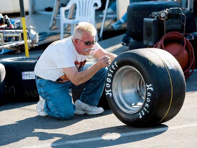
A Methodical Approach to Tuning
       and Development
• We need a plan…..testing or racing is more
  than just driving around

• Know your parts

• Know your car

• Line up support

                                               4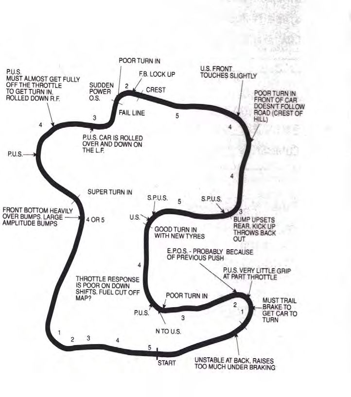
We Need A Plan
• Program objectives
   – Realistic, aggressive team goal
       •   New teams- research successful teams
       •   Established teams- build on experience
       •   Document and transfer knowledge to future teammates
       •   Scoring points in design event important, performance and
           reliability in dynamic events more important
   – Timeline with key milestones
       • The race will be run whether or not you’re ready
       • Stay on task and hit your key dates

• Winning programs “front load” development activity

• Testing is expensive- every test should take a step
  toward the goal
   – We wear out tires, brakes, diffs, engines. Make it count!

• Agree on priorities, test procedures before you go
  test [Communication among the system engineers!]                     5
Know Your Parts

                  6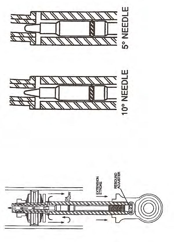
Know Your Car
• Visual, functional inspection of all systems
   – Brakes, Fuel, Steering, Suspension, Structure,
     Safety Gear

• Record static corner weights and suspension friction

• Physically measure center of gravity location (x,y,z)

• Physically measure bending and torsional stiffness of
  chassis (e.g. the 5th spring)
   – Torsional gradient plot axle CL to axle CL should
     not have large notches

      From “Race Car Engineering and Mechanics, Paul Van Valkenburgh,2000
                                                                            7
Know Your Car
•   Measure and plot front and rear hub motion through full bump and
    rebound travel
     – Toe change
     – Camber change

•   Design for adjustability (use “known” shims, adjustable dampers if
    budget and rules permit), saves time (your most important resource)

•   Use a damper dynamometer to characterize range of adjustments and
    damper component changes

•   Keep a logbook, record all changes to car

                                                                          8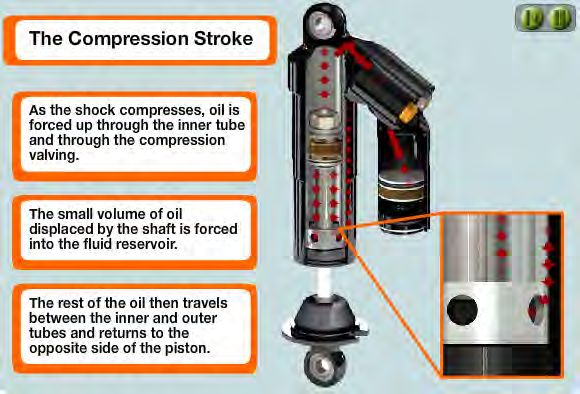
Line Up and Delegate Support
 – Hero Driver               – Tow vehicle/trailer
 – Data acquisition whiz     – Portable power source
 – Laptop computer           – Source of compressed
                               dry air or N2
 – Helpers/spotters/timers
                             – Tools
 – Radios
                             – Proof of liability
 – Timing equipment            insurance
 – Vehicle measurement       – Permission to use track
   equipment                   or lot
 – Weather station (really   – Restrooms
   helps your engine         – Refreshments
   calibrator)               – Enough fuel? Tires?

                                                         9
Take Some Opinion Out of Testing

• Stop watches, 2-3, digital
• Quality tire pressure gauge, 0-60 psi (2)
• Tire pyrometer- probe type (IR not as
  accurate)
• Durometer-Shore hardness A
• 4 bathroom scales
• Steel tape measure 12 ft, English/Metric
• Digital inclinometer
• Simple g-g measurement box (g-Tech,Escort,
  or part of data acquisition system)       10
How to Test
• Warm up vehicle at part throttle to get fluids, tires,
  brakes up to operating temps
• Check for fluid leaks before entering test surface
• Make two short low speed brake applications in pits,
  check for pedal travel and firmness
• The engine should be performing well to make
  meaningful chassis adjustments
• Driver should be prepared to work the edges of the
  friction circle
• Stay out just long enough to feel the change (or not),
  1-2 hot laps
• Make one change at a time, don’t be afraid to make
  big changes initially
• “Bracket in” on what seems to work
                                                       11
More Suggestions for Productive Testing
• Record every lap time (segments if you have more helpers) and on-
course driver comments (if radio)
• Create a track map/ driver debrief sheet for each session and use them
• Evaluate chassis performance only on new or scrubbed tires
• Evaluate chassis performance only after you have established good
throttle response
• You can always go back to the last iteration that worked when you keep
good records
• Take corner and straight segment times to find out where you are
gaining and losing time (don’t trust subjective judgments or lap times
alone)
• No excuses should be made or accepted—”we’re a half second slower,
but we have our weak motor in the car or if we had new tires or if the
sun wasn’t in the driver’s eyes….”
12
• Try to work with a physically and mentally rested driverCare and Feeding of Tires
• Keep a 3 X 5 card on each tire
• Record popping pressures to seat
beads when mounting tires to
wheels
• Check durometer at each test
along with ambient temperature
• Monitor inflation pressures before
and after each run
• Monitor tread temps (O/C/I) and
total number of heat cycles
• Monitor tread and shoulder wear
(chunking, blisters, rubber flow,
color change, fast wearout,
uneven wear)
• When adjusting pressures more
than 3 psi, recheck after one
minute
• Use dry air for inflation
• Record tire temps and pressures
right after each test
• Scrape junk off tread w/ hacksaw
blade, not your hands 13Tire Valves
• Valve cores can and do leak
• Metal caps and stems more
robust than plastic and
rubber
• Setups can be sensitive to
small air pressure losses
during extended runs
14Air Gauge
• Interpretation of tire pressure
requires an accurate gauge
• ANSI Commercial Grade B
gauges (meets ANSI B40.1
Grade B specifications)
recommended
• A digital gauge may be no
more accurate than an
analog gauge
Piston, plunger gauges are inexpensive, but
you may have to test a boxful to find an
accurate one (most not accurate to within +/- 5
psi)
Digital gauges are reliable and accurate
IF the strain gauge is properly calibrated
and fresh batteries are maintained
15How To Interpret Tread Wear
Blistering from excessive
inflation pressure (also note
the narrow grain pattern)
Example of good tire wear, small grain pattern and
Insufficient camber gain in roll, even wean across full tread arc
too little static camber Small camber adjustment to reduce graining, optimize grip
Source of marbles (Directional saw
tooth tips break off in shear, they can The tire does not
ruin your day off the racing line) lie. Severity of
grain pattern can
be evidence of
driver
compensation ,
driver abuse, or
poor setup
(excessive
throttle, or steer
inputs, wheelspin, 16
Photos from “The Racing and High etc.)
Performance Tire by Paul Haney, 2004Stagger Handling Effects
• Tire stagger may have a performance
benefit in road racing or autocross
depending on course layout, if you know
how to use it
• Tire stagger is the center of tread
circumference delta across an axle tire
pair
• Set cold pressure, use a steel tape
measure to determine each tire's
circumference, measuring at the center of
the tire. When checking hot pressure, re-
measure circumference to check for
change in stagger during run
• (Negative influence)
– Asymmetric left-right handling in
corners, slalom, or chicanes, and
slow straightline speed, tire stagger
could be a contributor
• (Positive influence)
– If you tune for stagger, helps left or
right corner entry under braking Jeff Honeycutt photo credit
(front), depending on the direction of
stagger
– Aids corner turn-in response (front)
– Depends on your rear differential
• Spool or live axle (aids all
17
phases)
• Locker style (aids accel only)Heat Cycling and Tire Temps
• Tire Scrubbing
– Mold release compound removed
– Tread compound is altered
– Tread durometer increases a few
points after cool down
– Running temp is reduced a few
degrees F
– Slower wear rate than stickers
– Time wise, scrubs are slightly slower
on the out laps, but are usually more
consistent and faster throughout a
long run than stickers
• Diminishing Returns
– Once the tire had exceeded its “cured
out” phase (too many heat cycles),
performance drops off
From “SAE Paper 2001-01-3606, The Formula SAE Tire Test Consortium-Tire Testing and Data
– Time to go to a fresh set Handling” , Kasprzak and Gentz.
18Camber and Tire Temps
• Try to achieve camber settings that
provide uniform temperature distribution
in the mid-corner phase (can be
determined on skid pad)
• Depending on the rest of your setup, this
could mean an aggressive static camber
setting
– May not be optimized for corner entry/exit
– Inside of tread at front and rear should be
5-10 deg F hotter than the outside when
measured in the pits
– More caster and/or camber may be used
in cold temps or a cold track to build temp
more quickly
• Consider more camber gain if it looks like
you are running too much static camber
Photo credit: Brian Snelson
19Keep Good Records!
• Method not important
• Use computer, notebook, or
other device
• Keep hard copies as backup
• Use a form or spreadsheet
for fast comparative analysis
• Bring your stuff when
presenting your car at
Design Judging!
• We are impressed by
organized data that supports
your claims and hard work!
20Dampers
• Primary function of damper, along with the spring, is
to keep the tire footprint in contact with the track
surface
• We generate tire mechanical grip by damping spindle
excitation due to road and body inputs
• The damper is our main tool to control the conflicting
requirements of maximum grip and balance
21A Few Words About Mountain Bike Dampers
• Suitable for forces generated by FSAE car
• Off the shelf MB dampers suitable for Rocky Mountain boulder
jumping, not suitable for FSAE car
• Basic MB valving develops too much compression force,
adjusters do not have enough range to adapt to FSAE
application
• MB dampers need to be custom valved for FSAE application,
start with baseline 3:1 rebound to bump control force ratio, scale
the control force range based on your car’s sprung and
unsprung masses and anticipated piston velocities for the race
track in question
• For road course and autocross, match damper control forces as
front pairs and rear pairs
• Request dynamometer control force curves for soft-mid-firm
high speed and low speed compression and rebound
adjustments @ 1, 3, 5, 10, 15, 25 ips and 1.5” stroke and gas
force measurement after warm-up cycle
2223
24
Damper Basics
•   Start with a base valve code that provides about 3:1 rebound to bump
    control force ratio

•   Account for the gas force of the damper in the overall spring rate and
    wheel rate of the suspension corner Note: Gas charge can effect ride
    height

•   Damper stiction increases as a function of charge pressure (don’t get
    carried away with the N2 bottle)

•   We need less bump since it damps the movement of the unsprung mass
    and doesn’t vary much due to dynamic loading, the rebound side damps
    the sprung mass reaction after the bump or weight transfer

•   Dampers control rate of weight transfer, not the amount

•   Overdamped- tire chatters over bumps, body control will be choppy, car
    will have nervous, darty feel, may lack progressivity in cornering with road
    camber, surface changes
•   Underdamped- body floats, steering response is sluggish, bouncing off
    bump stops                                                               25
How Much Damping Do We Need?
From Optimum G, Claude Rouelle, 2002
• Depends on mass and spring rate (example shown)
• The answer lies between ‘damped’ and ‘critically damped’
26Adjustable Dampers
1000
500
0
Peak Force (lbs)
0 5 10 15 20 25
-500
-1000
-1500
Cold R0C0
Cold R12C6
-2000 Cold R24C12
27
Velocity (in/sec)Monotube Low Speed Damping Force
Low speed flow is normally controlled by an orifice.
Oil Low
Pressure
Deflection Types of orifices:
Disc Stack Deflection Disc
X Stop
•Hole in piston (with or without one way valve)
Deflection
Disc Spacer
•Notch in disc
•Coin land
Piston For turbulent flow:
Flow Through
Bleed Orifice High
Pressure 2
Leakage Oil Q
Flow P= ‡
Piston Retaining C d ‡A eff 2
Nut
As flow rate Q is equal to relative velocity of the piston
times the area of the piston in compression (piston area –
Schematic of low speed compression valve flow. rod area in rebound):
At low speeds, total DAMPER force might be
influenced more by friction and gas spring than Orifice damping force is proportional to the square of the
damping. piston speed.
28Monotube Mid Speed Damping Force
Mid speed flow is normally controlled by a flow
compensating device.
Oil Low
Pressure Types of flow compensating devices:
•Deflection Discs ( typically stacked)
X
•Blow off valve (helical spring)
Preload on the valve determines the cracking pressure,
and hence the force at which they come into play. Define
the knee in FV curve.
Deflection Disc
Flow High
Pressure
Oil Preload:
•Disc, shape of piston, often expressed in degree.
•Disc, spring to preload (sometimes found in adjustable
race dampers)
Schematic of mid speed compression valve flow. •Spring, amount of initial deflection.
•Torque variation on jam nut can often vary preload.
Undesired for production damper,
With flow compensation pressure drop and force are
proportional to velocity.
29Monotube High Speed Damping Force
High speed flow is controlled by restrictions in effective
Oil Low flow area. i.e. effectively orifice flow.
Pressure
X Flow restrictions, typically which ever has smaller effective
area:
•Limit of disc or blow off valve travel.
•Orifice size through piston.
Deflection Disc
High
As per low speed damping, pressure drop and force are
Flow
Pressure proportional to velocity squared.
Oil
Rebound damping and pressure drops across
compression heads (foot valves) are similar to those
discussed here.
Schematic of high speed compression valve flow.
30Tuning to Develop Damping Map
• Current designs permit up to 4 way
control force adjustment
– Low speed compression
– High speed compression
– Low speed rebound
– High speed rebound
• We’re referring to damper piston speed,
not vehicle speed
31Starting Out
• Set up basic vehicle course to “rough in” damper settings (I use
a figure 8 with 2 different radii circular segments)
• Evaluate vehicle first for wheel end control, then ride, roll, and
pitch control
• Use your most experienced driver
• Start with all dampers set at full soft for LSC,LSR,HSC,HSR
• Work with one axle pair at a time, sweeping HSC full soft--
>mid-->full firm (Note: HS change can effect LS force
characteristics)
• Back off HSC ‘X’ number of sweeps until tire bounce/dribble
and ride harshness subsides, then repeat with other axle pair
• Continue with LSC same method as HSC
• Check gas charge setting to provide additional support, if
needed) to the front end for initial roll control and corner entry
• Continue with HSR and LSR, looking to tighten up body motion
and stabilize the platform for roll, squat and dive weight transfer
• With rebound, back off HSR ‘X’ sweeps when car breaks 32
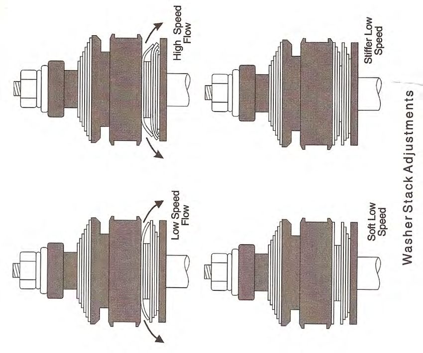
traction or if jacking down/cavitation is observedShim Stack and Adjusters The needle taper determines the sensitivity of the adjuster detent The section profile of the shim stack determines the transition curve shape between low speed and high speed control From “Inside Racing Technology, Braun and Haney, 1995 33 forces
Building a Damping Map
     The adjuster usually consists of an angled needle metering fluid flow across a hole

1)                                                              2)

                                                                           From Optimum G, Claude Rouelle, 2002

3)             Low speed                Mid speed           High speed
                                                                             FYI: Low, mid and high speed are relative terms
                                                                                    depending on the type of car (Indy car, off
                                                                                    road buggy, rally car, etc.). Off road/rally cars
                                                                                    plot up to 120 ips @ 10” stroke

                                                                     1) Piston bleeds,coined lands, and piston
                                                                     dish determine LS and nose, 2) shim stack
                                                                     determines MS and F-V slope, 3) piston
                                                                     holes/slots determine HS end point
                                                                                                                           34
Tuning Your Car with Driver Feedback From “Tune to Win”, Carroll Smith, 1978 35
Breaking Down The Course
       or Only the Driver Can Balance the Car
– Corner Entry- turn in response, weight transfer under braking,
  pitch/dive, brake pull or weave, transient roll balance, understeer/
  oversteer, steering efforts
– Corner Apex- understeer/oversteer , steer corrections, throttle
  applications, path firmness
– Corner Exit- understeer/oversteer, rate of power application
  coming off the corner (diff torque distribution, weight transfer under
  acceleration, wheelspin, weaving)
– Straightaways : straight line tracking, pitch attitude (stiction leaving
  the corner)-can affect steering and aero lift/drag
– Slaloms and chicanes- Front to rear steering coherence, lateral
  grip and roll rates in transitions, ability to maintain tight line with
  cones, oversteer/understeer balance, steering efforts
– Skidpad- Amplitude and frequency of steering corrections and
  throttle modulation to maintain circle at peak lateral acceleration,
  watch for oil pressure and fuel pressure fluctuations

                                                                        36
Straight Line
• Driver: “The car pulls or wanders”
– Too much static rear toe-out or dynamic
bump steer or compliance steer
– Extreme front toe-in or toe-out
– Failed pickup point
– Damper with no control
• Driver: “Unstable under hard accel”
– Too little rear toe-in
– Rear tire stagger
– Failed rear damper
– Pickup point or suspension component
compliance
– Very asymmetric corner weights
• Driver: “Very darty over single wheel
bumps”
– Too much Ackerman steer
– Too much toe-in or toe-out
– Caster stagger
– Front anti-roll bar rate too high
– Jounce bumper block height too tall or
nose rate too high
• Driver: “Car is a POC”
– Time for a break or driver change
– Revert to last setup combination that
worked 37Hard Braking
• Driver: “Front end weaves”
– Too much front brake bias
– Too much low speed rebound
control (jacking down)
• Driver: “Wants to spin”
– Too much rear brake bias
– Not enough rear suspension
rebound travel
– Too much rear damper low speed
rebound control
– Too much rear roll stiffness
– Not enough rear camber
38Corner Entry
• Driver: “The car points initially then
plows” [Undertseer]
– Too much front toe-in or toe-out
– Too little front rebound travel
– Front spring shims misadjusted
– Too little front damper low speed
compression force
– Too little front roll stiffness {the outside
front tire rolling over}
• Driver: The car wants to over-rotate on
turn-in” [Oversteer]
– Heavy trail braking by the driver
– Way too much rear brake bias
– Rear ride/roll stiffness too high relative to
front
– Rear roll center too high
– Non-functioning front anti-roll bar
39Corner Apex
• Driver: “Too much push in the
middle of the turn”
– Front tire pressures too high
– Front roll stiffness too high
– Too much toe-in or toe-out
– Too much Ackerman correction
– Not enough camber-in-turn (static
caster)
– Front track width too narrow
– Not enough front jounce travel
(damper bottoms out or spring not
shimmed properly)
40Corner Exit
• Driver on slow corner: “I keep
plowing off the corner” [Understeer]
– Patience! Condition probably
originated at corner entry or apex
(chassis or driver induced). Driver
uses throttle stabs to try to rotate the
car. Tell driver to carry less speed at
corner entry
• Driver on fast corner: “The nose is
heading for the fence on exit”
– Not enough squat control resulting
in rearward weight transfer with hard
throttle
– Need more rear damper low speed
jounce force, maybe coupled with
more front damper low speed
rebound force
– Too much preload on differential
clutch pack
41Chicane or Slalom
• Driver: “Steering feel is heavy, response
is sluggish”
– Tire pressure too low
– Ride and roll rates too low
• Driver: “ The chassis feels floppy. It rolls
a lot. Doesn’t take a set when I turn-in, I
can’t point the car”
– Low tire pressure
– Low and mid speed damper forces too
low, not enough “nose” on the curve
– Ride and/or roll rates too low
• Driver: “ The steering response is hyper”
or “ the car wants to get out from under
me”
– Tire pressure too high
– Damper low and mid speed compression
force to high
– Ride and/or roll rates too high
– Too much toe in (front or rear)
42For More Help On
Chassis Tuning Cause and Effect
43Chassis Setup Review
• Remember Maurice Olley shoot for 20% delta front to rear ride frequencies to achieve
“flat ride”
• Suspension tuning hierarchy: springs, anti-roll bars, dampers
• Wheel alignment hierarchy: toe, camber, caster
• Limit anti-dive to about 30%, anti-squat to about 40% (IRS) if you use them in your
suspension geometry
• My philosophy: the springs contribute 60-75% of roll stiffness, use anti-roll bars to “trim out”
the roll couple distribution, not a big advocate for rear anti-roll bars
• Dampers: Start at 3:1 rebound to bump ratio, bracket damping, charge dampers with dry air
or N2 to about 200 psi (monotube), 100 psi (twin tube) to avoid cavitation or dumping.
Control force ratios above 6:1 prone to jacking the car down on ripples, washboard, or
longer cold patch asphalt sections. With adjustable dampers, start at full soft
LSC,HSC,LSR,HSR and build your damping map
• Tires: Use old tires for training, new tires/scuffs for testing/racing, use tire maker cold
inflation and working pressure recommendations to start chassis sorting. Take hot
pressures and tread temps as soon as the car rolls to a stop. Check for evidence of stagger,
compare hot to cold tire measurement
44Thanks for Your Attention
Copyright © 2011 Steve Lyman. All rights reserved.
45You can also read