SW5484E Compact Configurable Vibration Switch Installation Manual - Metrix-Vibration
←
→
Page content transcription
If your browser does not render page correctly, please read the page content below
SW5484E Compact Configurable Vibration Switch
Installation Manual
                                    OVERVIEW
                                    The SW5484E is a loop powered seismic velocity
                                    transmitter and configurable switch. The compact
                                    vibration switch incorporates a piezoelectric accel-
                                    erometer, signal integrator, RMS or peak detector,
                                    4-20 mA signal conditioner and a digital microcon-
                                    troller into a single package. It is mounted directly
                                    on a machine case or bearing housing without
                                    intervening signal conditioning equipment. The
                                    switches can be used in an auto-shutdown or alarm
                                    circuit that trips the machine under high vibration
                                    conditions. Two independent configurable alarm
                                    setpoints and corresponding discrete outputs al-
                                    low implementation of ALERT (pre-shutdown) and
                                    DANGER (shutdown) levels by the machine control
                                    system. A separate 4-20 mA proportional velocity
                                    output is also provided, allowing connection to
                                    PLCs, DCSs, strip chart recorders, or other process
                                    monitoring systems where vibration levels can be
                                    trended. The unit comes with an 8-Pin MIL Style
                                    Connector or bundled flying leads, and includes
                                    the dynamic raw acceleration signal provided
                                    through two of the 8 pins.

                                    The 8-Pin MIL Style Connector comes with an in-
                                    creased safety rating and can be used with barriers
                                    for special installations. For explosion proof instal-
                                    lations, wire directly to explosion-proof conduit fit-
                                    tings using the flying lead version with the included
                                    elbow.

                                    The SW5484E has no moving parts and is encapsu-
                                    lated in a 316 stainless-steel housing. Each switch
                                    is factory calibrated to the sensitivity marked on
                                    the label. The setpoint and time delay of the two
                                    switch channels can be configured from software.
Doc# 1874511 • REV B • March 2021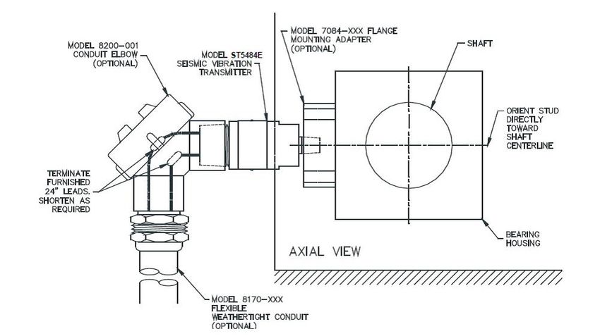
Refer to Metrix Datasheet 1862019 for specifications, ordering information, and outline di-
mensions.
Solid State Relays
The solid state relays included in the switch can carry a maximum
current load of 100 mA. If you need a higher current carrying capacity
use an interposing relay with a 50 mA holding current like:
idec: RSSDN-10A DC Input Solid State Relay
idec: RSSAN-10A AC Input Solid State Relay
idec: RU2 Series DPDT Universal Relay
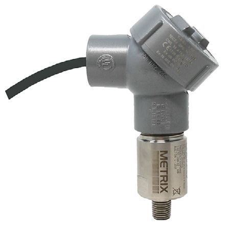
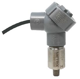
8-Pin MIL Connector Flying Leads
(Option D=8) (Option D=7 and 9)
Increased Safety *Explosion Proof
*Explosion Proof Version
Option D=7 and 9
Note: Units sold with an explosion proof rating
will include an 8200 explosion proof
elbow that will be affixed at the factory.
MOUNTING
It is important to solidly mount the SW5484E body to the machine surface. Refer to section
6 on transducer placement. Different machine preparations are required for the two basic
SW5484E mounting styles; NPT (National Pipe Thread) and machine thread (UNF and Metric).
Devices with the NPT type mounting stud are secured by the thread engagement and the
base of the SW5484E does not contact the machine surface. Devices with the machine thread
studs must contact the machine surface. The base of the SW5484E must make square and
direct contact. This requires preparing the surface of the machine with a 1 1/2 inch counter
bore (surfacing tool). This tool can be used with a portable drill equipped with a magnetic
base but care must be taken so that the tapped and threaded hole is perpendicular to the ma-
chined surface. The SW5484E must make contact all the way around its base surface. Contact
Doc# 1874511 • REV B • March 2021 Page 2 of 14
Metrix for more detailed counter bore instructions.

If installing a SW5484E with a standard 1/4 inch NPT stud, drill a hole using a 7/16 inch bit, 5/8-
7/8 inch deep. Then tap using a 1/4 - 18 NPT (tapered pipe tap). Hand-tighten the SW5484E
and then turn an additional 1 to 2 turns using a wrench on the wrench flats. Do not use a pipe
wrench. A pipe wrench can apply extreme forces to the body and potentially damage electronic
components. A minimum of five (5) threads of engagement should be made. A 1/4 inch to 1/2
inch NPT bushing is available for mounting the SW5484E in existing 1/2 inch NPT holes. Also, a
Metrix model 7084 Flange Adapter can be used between the SW5484E and the machine surface
when there is not enough surface thickness to drill and tap a hole. The flange adaptor mounts
with three small screws (1/4” X 28).

If installing a SW5484E with one of the straight machined thread sizes, follow standard drill and
tap procedures. Do not drill a hole larger that the counter bore pilot diameter before using the
counter bore to prepare the machine surface. Drill out the hole with the correct tap drill size
after preparing the surface.

The sensitive axis of the SW5484E is in line with the mounting stud. The SW5484E can be ori-
ented in any (0 to 360 degree) position.

WIRING
3.1 General
The SW5484E is connected like other loop powered SW5484Es. The following is a summary
based on area designations.

                        CAUTION: Use of a high-speed torque screwdriver
                        may damage the terminal blocks.

Connect the field wiring in accordance with the appropriate portion of Figure 1.

The SW5484E requires a minimum of 11 VDC for proper operation. This is the minimum volt-
age required at the SW5484E (not the power supply), after all other voltage drops across field
wiring and receiver input impedance have been accounted for with the maximum 20mA of loop
current flowing. The minimum loop power supply voltage required is therefore 11 VDC plus 1
volt for each 50 W of total loop resistance.

                    7
      Dynamic
                    8

                    1
      SW1
                    2
                    3
      SW2           4

      4-20 mA       5
                    6
                                                              sw2    sw2 swl       swl
                                    -         +                +      -     +       -       -
                                                                                         Dynamic   Dynamic
                                                                                                      +
                                    PLC or other                    PLC or other            Monitoring
Figure 1:                           Loop power                       Switching               System

                                                   Doc# 1874511 • REV B• March 2021 Page 3 of 14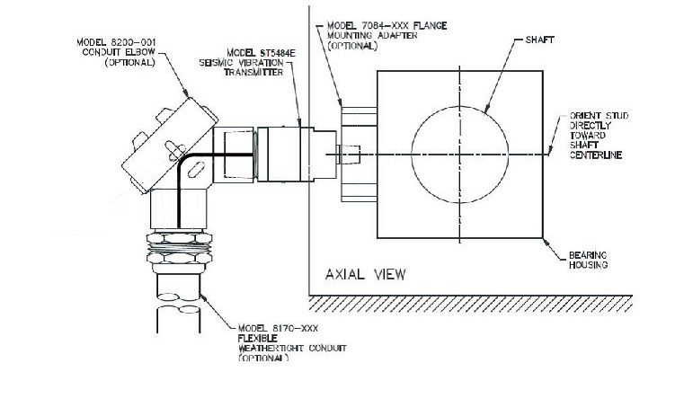
Example:
 Component                           Resistance
 Signal wiring                       10 W
 DC Input Impedance of receiver      250 W
 TOTAL LOOP RESISTANCE               260 W

Minimum supply voltage = 260 W (1 V/50 W) + 11 V = 16.2 VDC

The maximum loop power supply voltage that may be applied is 30VDC (explosion proof and
increased safety). The maximum loop resistance (LR) is calculated by the equation: LR = 50
(Sv - 11) W, Sv=Supply Voltage
Example: LR = 50 (24 - 11) = 650 W for a 24 VDC loop supply.

The maximum raw signal distance from the switch is 10 meters (33 feet). Length longer than
this will result in raw signal degredation.

3.2 Explosion-Proof Installation In Hazardous Locations (CSA)
Some models of SW5484E are CSA certified explosion-proof, CSA US/C, Class I, Div 1, Grps
B-D and Class II, Div 1, Grps E-G (explosion proof). Connect the field wiring in accordance
with the appropriate installation as shown in Figure 1. Refer to section 3.1 for loop volt-
age and resistance requirements. All conduit and junction boxes used must be certified
explosion-proof for the class, division, and group required by the application. Installation
of the SW5484E must meet all of the explosion-proof installation requirements of the local
governing agency and facility safety procedures. The Metrix part 8200-000 elbow is required
to meet this approval.

3.3 Flame-Proof Installation In Hazardous Locations (ATEX, IECEX)
Some models of SW5484E are ATEX/IECEx certified flame-proof, Ex d IIC T4 Gb. Connect the
field wiring in accordance with the appropriate installation as shown in Figure 1. Refer to sec-
tion 3.1 for loop voltage and resistance requirements. All conduit and junction boxes used must
be certified flame-proof for the area required by the application. Installation of the SW5484E
must meet all of the flame-proof requirements of the local governing agency and facility safety
procedures. The Metrix part 8200-000-IEC elbow is required to meet this approval.

3.4 Software
A. Two independently adjustable setpoints – The use of two setpoints* (one for ALERT and
one for SHUTDOWN) is recommended for applications where it is desirable to remotely
annunciate an ALERT condition to operators and/or maintenance personnel. This allows
appropriate intervention to occur before the machine reaches SHUTDOWN levels. Switches
with only a single setpoint are not capable of pre-shutdown warnings unless the 4-20mA
output is connected to a PLC or other trending device, and appropriate pre-shutdown alarm
limits are programmed in the PLC.

* NOTE: The two setpoints are set at the factory at one fourth (1/4) and one half (1/2) of the
full scale range, and they can both be adjusted through Metrix software.

B. Relay Operation – The solid state relays of the SW5484E are shipped Normally Open (NO)
with a 3 second time delay, which means that when the vibration set point is exceeded three
seconds later the relay will shut. If power is removed from the device the relays will remain
open. Using the User Software and the Dongle the set points and time delays can be
changed. To meet the SIL certification requirements the user must change the relay setting

Doc# 1874511 • REV B • March 2021 Page 4 of 14
to Normally Closed (NC) using the User Software and the Dongle. NC means that when the
SW5484E is energized, or 4-20 mA loop power is provided, the relays are closed. The NC set-
ting is considered “Fail Safe” as the contacts will open on loss of power to the device.

C. Latching Operation - The solid state relays of the SW5484E are shipped Non-Latching,
which means that when the vibration set point is exceeded, and the time delay has expired,
the relay will change state. If the vibration level goes less than the alarm setpoint, and Non-
Latching is selected for the relay, the relay will automatically change to its original state. If
either or both relays are set to Latching, which means that when the vibration set point is
exceeded, and the time delay has expired, the relay will change state. If the vibration level
goes less than the alarm setpoint, and the Latching mode is set, the relay will not change
state until 4-20 mA loop power is momentarily removed to reset the Latched alarms. Latch-
ing must be selected for each relay in order to meet the SIL requirements.

D. LOCKOUT (Power-Up Alarm Inhibit) capabilities – Configurable LOCKOUT capability is
available for suppressing alarm activation during tranducer startup conditions.

* NOTE: This delay is set at the factory for 10 seconds and can be adjusted in the field by us-
ing Metrix software up to 300 seconds.

E. Flexible Discrete Output Types – The solid state relays can be used as discrete outputs to
externally annunciate alarm conditions and to use the switch as part of an auto-shutdown
(i.e., trip) circuit. Switches provide two discrete outputs – one for ALARM and one for
SHUTDOWN. The outputs can be individually field-configured to have separate time delays
and separate shelf states (open on alarm or close on alarm). Solid-state relays are designed
primarily for applications where the discrete output(s) will be connected to a light load, such
as a PLC, DCS or to an interposing relay with a maximum 50mA holding current.

                                                Doc# 1874511 • REV B• March 2021 Page 5 of 14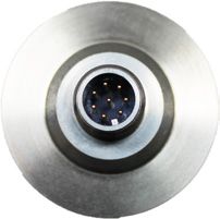
Doc# 1874511 • REV B • March 2021 Page 6 of 14
The solid state relays included in the switch can carry a maximum current load of 100
mA. If you need a higher current carrying capacity use an interposing relay with a 50 mA
holding current like:

         WARNING:
         ATEX Conditions for Safe Use (Ex d)
         For temperature classification and safety:

  •    Use conduit elbow, Metrix reference 8200-000-IEC, which is a Killark product with
       reference: Y-3-EX.
  •    Ambient Operating Temperature: -25°C to +100°C

         WARNING:
         CSA Equipment Installation Requirement per ordinary locations standards,
         C22.2/UL 61010-1:
  Applicable for permanently connected equipment:
            a) A switch or circuit-breaker must be included in the installation;
            b) It must be suitably located and easily reached;
            c) It must be marked as the disconnecting device for the equipment.
  Equipment environmental Ratings:
            a) Pollution degree 3
            b) Installation category I
            c) Altitude 2000m
            d) Outdoor: Type 4x
            e) Temperature -25°C to 100°C

                                             Doc# 1874511 • REV B• March 2021 Page 7 of 14
4. ELECTROMAGNETIC COMPATIBILITY
In order to meet the requirements of electromagnetic compatibility in areas of high electro-
magnetic interference, the field wiring must be:
• Shielded twisted pair cable enclosed in grounded metallic conduit, or
• Double shielded twisted pair cable with a metallic body cable gland fitting and with the
outer shield grounded.
Use standard two-conductor, twisted pair, shielded wiring for the long run to the instrumen-
tation enclosure. The SW5484E is connected like other loop-powered end devices.
NOTE: Metrix also strongly recommends the use of our ferrite bead kit (Metrix p/n
100458) as an extra precaution against electromagnetic interference that may be
induced in field wiring from subsequently bleeding into the SW5484E.
When vibration level SW5484E output PLC (or other) should read…
at SW5484E is… will be…
0.0 in/s (i.e. no vibration) 4.0 mA (± 0.1 mA) 0.00 in/sec
1.0 in/s (i.e. full scale vibration) 20.0 mA (± 0.5 mA) 1.00 in/sec
Momentary “jolts” that can occur at start-up, or during some operating condition changes, do not
reflect a machine’s steady-state operating condition. To prevent such occurrences from generating
nuisance alarms, program a time delay into the alarm such that the indicated vibration level must
persist above the alarm setpoint for a preset period of time before an alarm is generated. The
indicated vibration level must cross the threshold level and stay above it for a preset time before
any alarm action is taken. A 2 to 3 second delay is normally applied to most machinery. Consult
Metrix if you have a question about your machine’s operating characteristics.
The SW5484E has a start-up time lockout for alarms. A start-up lockout is different than a time
delay. A start-up lockout functions the same as a time delay, but is usually set to a much longer
time. Both may be needed.
5. CONNECTION TO PLC OR OTHER INDICATING INSTRUMENT
The first step in configuring the PLC, DCS, or other recording instrument is to determine the source
of power. The SW5484E requires loop power. Some analog input channels on a PLC or DCS, for
example, provide this power from within. If they do not provide power, an external power supply
must be provided. Connect the SW5484E field wiring using standard instrumentation practices.
Scaling of the display is on the basis of the range of the SW5484E. The measurement parameter
name is “vibration” and the units are “in/s” (inches per second) or “mm/s” (millimeters per sec-
ond). The example below is based on a standard 1.0 in/s SW5484E.
Doc# 1874511 • REV B • March 2021 Page 8 of 146. TYPICAL DEVICE PLACEMENT
The SW5484E measures seismic vibration (i.e., vibration velocity) at the attachment point on the
machine, using engineering units of in/s (inches per second) or mm/s
(millimeters per second) depending on the selected ordering option.
The devices’s sensitive direction is through the long axis of its cylindri-
cal body. It will not measure side-to-side motion. Typical SW5484E
mounting for casing vibration measurements is in the horizontal direc-
tion at the bearing housings as depicted in Figure 2. The horizontal
direction usually incurs more vibration because most machines’ foun-
dation constrains vertical vibration more than horizontal vibration. A
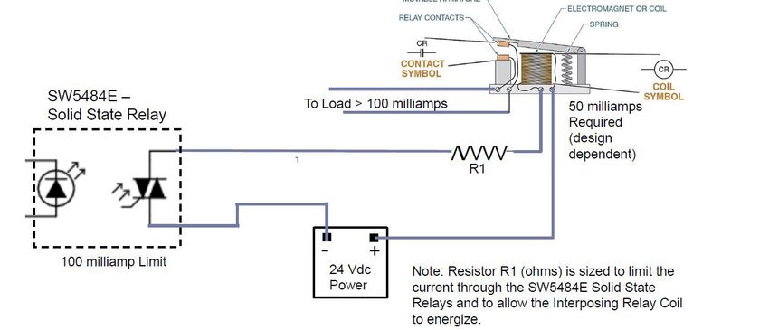
horizontal mounting arrangement is also depicted in Figure 3, but Figure 2:
with additional detail showing typical accessories. When flying leads Typical SW5484E
are ordered, a 5 meter or 10 meter length may be specified using mounting
ordering option D on the Metrix product datasheet 1862019. These leads may be cut to length
and then spliced to field wiring as shown in Figure 3.
NOTE: Hazardous area locations do not allow a splice at the location shown
in Figure 3. Instead, the splice must be made in a second conduit hub
(meeting splicing requirements) located at the end of flexible conduit.
When attaching conduit to the SW5484E, observe the following:
• Because the SW5484E is sensitive to vibration, avoid unsupported lengths of conduit and ex-
cessive mass (such as large hubs or junctions) hanging directly off the end of the SW5484E.
These can introduce unwanted vibrations that do not reflect actual machinery vibration and
cause mechanical stresses that can lead to premature transducer failure.
• A “Y” type conduit elbow, such as the Metrix 8200 series, is preferred because it prevents
the conduit from extending too far away from the SW5484E, thus limiting the likelihood of
breakage. It also precludes long unsupported lengths of conduit directly aligned with the
devices bore (longitudinal axis) as noted in the bullet above.
• Avoid attachment of rigid conduit directly to the SW5484E; instead, use a small length of
flexible conduit to mechanically isolate the SW5484E from vibration that might occur in rigid
conduit.
• If a 1-inch to 3/4-inch reducer is used at the elbow, a smaller diameter flexible conduit can
be used.
Figure 3
Doc# 1874511 • REV B• March 2021 Page 9 of 147. CALIBRATION
The SW5484E has been factory calibrated for the full-scale vibration level marked on the la-
bel. If the calibration is in doubt, the unit can be verified in the field by following the proce-
dures outlined below. Note that there are no Zero and Span adjustments on the SW5484E.
Additionally, the SW5484E uses a true RMS amplitude detection circuit; units supplied with
a full scale range in peak units scale the underlying RMS measurement by a factor of 1.414
to provide a “derived peak” rather than true peak measurement.
7.1 Zero Verification
In the absence of vibration the output current should be 4 mA ± 0.1 mA. If the ambient
vibration exceeds 2% of full scale, the SW5484E should be removed from the machine and
placed on a vibration free surface for this measurement. Often a piece of foam can be used
to isolate the SW5484E from external motion.
7.2 Span Verification
Subject the SW5484E to a known vibration within the full scale range marked on the label.
If you are using a portable vibration shaker where it can be tested at full scale, the output
should be 20 mA ± 0.5 mA.
8. DYNAMIC OUTPUT
The SW5484E includes the dynamic output is an acceleration signal with a sensitivity of 100
mV/g, filtered to the same frequency band as used for the 4-20mA velocity measurement.
Observe the following when using this output:
• Only an electrically-isolated or battery-powered portable vibration analyzer should be
used when connecting to this output. Since this is a loop-powered device, an external
ground will affect the loop output and could cause a false alarm.
• When using a portable vibration analyzer or data collector, be sure to turn the instru-
ment sensor power off.
• Most portable vibration analyzers have a low input impedance and they will load this
signal, resulting in attenuation of as much as 20% to 30%. Refer to Table 1 which
shows the nominal attenuation expected for a given input impedance.
• In all cases for all locations, the use of this signal is for temporary connection only. Per-
manent connection could violate hazardous location installation requirements.
• Avoid impacting the SW5484E or introducing other mechanical vibrations when con-
necting to this output. Such vibration could result in spurious alarms or machinery
trips.
• When output is not in use, be sure leads cannot touch conduit or each other as this will
affect the 4-20 mA current output.
• Avoid introducing electrical noise when using this output. Do not use this output with
leads longer than 10m (33 feet). Use of longer leads can introduce electrical noise and
attenuate high-frequency signal content that may be present in the raw acceleration
signal.
Doc# 1874511 • REV B • March 2021 Page 10 of 14Connect In Color Code Dynamic Signal Table 1
Type Connections Input Impedance dB
MIL- Brown 1 = Switch 1 - of Analyzer Attenuation
C-5015 Brown/White 2 = Switch 1 + 10 MEG 0.01
8-Wire Blue 3 = Switch 2 -
Blue/White 4 = Switch 2 + 5 MEG 0.02
Orange 5 = Power + 2 MEG 0.04
Orange/White 6 = Power -
Green 7 = Dynamic 1 MEG 0.09
Green/White Signal + 500 K 0.18
8 = Dynamic
Signal - 200 K 0.43
100 K 0.84
50 K 1.61
20 K 3.57
10 K 6.10
9. SPECIFICATIONS, ORDERING INFORMATION AND OUTLINE
DIMENSIONAL DIAGRAMS
Refer to Metrix product datasheet 1862019 for additional information.
Figure 4:
Figure 4: Outline dimensions of the SW5484E Flying Lead Version. Dimensions in mm [inches].
8200-000 IEC conduit elbow shown installed, necessary for Explosion Proof rating.
* NOTE: 8200-000-IEC elbow is mandatory for ATEX/IECEx/INMETRO/KOSHA/EAC Ex d (flame-
proof) approved installations. The 8200-000 elbow is mandatory for CSA Ex d (flameproof)
approved installations.
Doc# 1874511 • REV B• March 2021 Page 11 of 14Figure 5:
Figure 5: Outline dimensions of the
SW5484E-XXX-XX8-XX (MIL-Style Connector). Dimensions in mm [inches].
info@metrixvibration.com
www.metrixvibration.com
8824 Fallbrook Dr. Houston, TX 77064, USA
Tel: 1.281.940.1802 • Fax: 1.713.559.9421
After Hours (CST) Technical Assistance: 1.713.452.9703
Doc# 1874511 • REV B • March 2021 Page 12 of 1411. HAZARDOUS AREA APPROVALS
MODEL SW5484E
IECEx Approval IEC Markings: IEC Standards:
(World): Model SW5484E-XXX-XX8X-XX: IEC60079-0:2017
Ex db IIC T4 Gb IEC600079-1:2014
-40°C≤Tamb≤+100°C WARNING: DO NOT OPEN
IECEx LCI 11.0025X WHEN ENERGIZED
Model SW5484E-XXX-XXDX-X: IEC60079-0:2017 ATTENTION: NE PAS OUVRIR
Ex ec IIC T4 Gc IEC600079-11:2011 QUAND ÉNERGISÉ
-40°C≤Tamb≤+100°C
IECEx LCI ??.????X
ATEX Approval ATEX Markings: EN Standards:
(Europe): Model SW5484E-XXX-XX8X-XX: EN60079-0:2018
II 2G Ex db IIC T4 Gb EN60079-1:2014 EP : Certified explosion proof,
-40°C≤Tamb≤+100°C Class I, Groups B,C,D ; Class II,
LCIE 11 ATEX 3017X Groups E,F,G
« SEAL NOT REQUIRED »
Model SW5484E-XXX-XXCX-XX: EN60079-0:2018
II 3G Ex ec IIC T4 Gc EN60079-11:2012 Ex ia : Intrinsically Safe for Class
-40°C≤Tamb≤+100°C I, Groups A,B,C,D when installed
LCIE ?? ATEX ????X as per drawing 9426
UL Approval CSA Markings: CSA/UL Standards:
(North Models SW5484E-XXX-XX1X-XX or SW5484E- CSA C22.2 0-10
America): XXX-XX2X-XX: CSA C22.2 25-1966
Class I, Div 1, Groups B,C,D; Class I, Div 2, CSA C22.2 30-1986
Groups A,B,C,D; Class II, Div 1, Groups E,F,G; CSA C22.2 94-M91
T4 or T4A; Type 4X; -40°C≤Tamb≤+100°C CSA C22.2 157-M1992
CSA C22.2 61010-1-12
Model SW5484E-XXX-XX4X-XX: UL 61010-1
Class I, Div 1, Groups A,B,C,D; T4 or T4A; UL 50
Type 4X; -40°C≤Tamb≤+100°C; Vmax=29.6V, UL 913
Imax=100mA, Vi=70.4nF, Li=0.5uH UL 1203
ANSI/ISA-12.12.01-2011
Doc# 1874511 • REV B• March 2021 Page 13 of 1410. ENVIRONMENTAL INFORMATION
This electronic equipment was manufactured according to high quality stan-
dards to ensure safe and reliable operation when used as intended. Due to its
nature, this equipment may contain small quantities of substances known to be
hazardous to the environment or to human health if released into the environ-
ment. For this reason, Waste Electrical and Electronic Equipment (commonly
known as WEEE) should never be disposed of in the public waste stream. The “Crossed-Out
Waste Bin” label affixed to this product is a reminder to dispose of this product in accor-
dance with local WEEE regulations. If you have questions about the disposal process, please
contact Metrix Customer Service.
Doc# 1874511 • REV B • March 2021 Page 14 of 14You can also read