System Evolution with 100G Serial IO - Ali Ghiasi Ghiasi Quantum LLC 100 Gb/s/Lane NEA Meeting New Orleans May 24th, 2017 - IEEE 802
←
→
Page content transcription
If your browser does not render page correctly, please read the page content below
System Evolution with 100G Serial IO

                   Ali Ghiasi
              Ghiasi Quantum LLC

           100 Gb/s/Lane NEA Meeting
                  New Orleans

                May 24th, 2017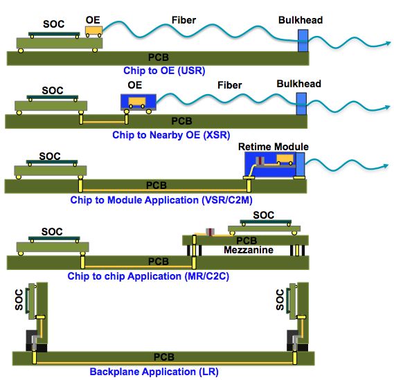
Overview
q Since 10GBASE-KR superset ASIC SerDes have supported C2M, C2M, and backplane
  applications
       – Adding KR/CR capability provided a solution to support Cu DAC and backplane small power penalty
       – The superset KR/CR SerDes supported C2M pluggable optics
q At 112G need to reconsider our historical architecture to make sure the system is cost and
  energy efficient
q Expect 112G signaling to be based on PAM4 for following reasons:
       – Higher order modulation such as PAM8, PAM12, PAM16 require stronger FEC with higher latency and eco-
         canceller due to discontinuity in the channels
       – More complex FEC and eco-canceller can’t be integrated into large ASICs
       – Any chip-to-module signaling other than PAM4 require a convertor chip for 100GBASE-DR and 400GBASE-DR4
       – Any FEC other than RS (544,514) require FEC termination and initiation in the module for 100GBASE-DR and
         400GBASE-DR4 with significant latency impact
q Considering eco-system requirement this contribution only considers PAM4 with KP4 FEC for
  112G applications!

A. Ghiasi                                            NEA Meeting
                                                         2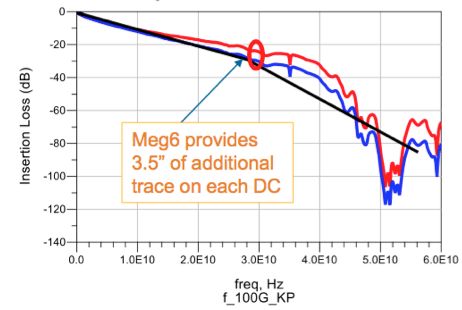
The 50G/lane Interconnect Ecosystems
       q OIF has defined both NRZ and PAM4 for MR, VSR, XSR, and USR
       q IEEE P802.3bs and P802.3cd are defining PAM4 signaling for 50G/lane Chip-to-chip, chip-to-
         module, Cu DAC, and backplane
Application                Standard        Modulation        Reach              Loss             Loss                  Defined in OIF
                                                                              Ball-ball       Bump-bump
Chip-to-OE (MCM)         OIF-56G-USR           NRZ           < 1cm         2 dB@28 GHz            NA
                                                                      1
Chip-to-nearby OE        OIF-56G-XSR          NRZ/
The 100G/lane Eco-System will be follow
50G Eco-system
q With estimated loss of 18 dB C2M specification is inline with our definition of C2C
– Bump to bump loss calculated by assuming ASIC package with 6 dB loss and small CDR package having 2 dB loss
– 6 dB ASIC package assumes 30 mm trace and requires material better than GZ41
– PCB reaches below assumes Tachyon 100/Megtron 7 OIF has defined USR/XSR but with little traction so far!
– C2M with 18 dB loss is more inline with current C2C SerDes
– Should we consider defining OBO and/or MCM applications?
Application Standard Modulation Reach Ball-Ball Bump-Bump
Loss Loss
Chip-to-OE TBD PAM4 < 1 cm NA 2 dB
(MCM)
Chip-to-nearby OE TBD PAM4Conventional Backplane no Longer Feasible at 100 Gb/s!
q TE Whisper 40” conventional backplane at 100 Gb/s PAM4 Nyquist has a loss of ~65 dB *
q 1 m cabled backplane is viable with short daughter-card, in effect every lane needs a retimers!
TE Whisper Conventional Backplane 40” with Meg 6 HVLP * TE Whisper 1 m Cabled Backplane **
EQ Can equalize the Channel
Even High Power 10GBase-T
100 Gb/s PAM4
4” DC Trace EM-888
7.7” DC Trace Meg 6
* TE Whisper channel, http://www.ieee802.org/3/cd/public/channel/Reference_document_for_TE_Connectivity_Backplane_S-Parameter_Channels_07_28_16.pdf
** Achieving 100 Gb/s Channels, David Hester TE Connectivity, OIF 2016 100 Gb/s Workshop.
A. Ghiasi NEA Meeting 5When do we need 100G signaling?
q Product based on 112G/lane are expected to be deployed by 2021
1000"
112G/lane
224G/lane
The end of Conventional Backplane
56G-PAM4
Replace
Signaling"Rate"on"Backplane"(Gb/s)"
With coax
cabled
28G-NRZ
100"
10GBase-T Backplane
TH Pre-coding Or optical
LDPC FEC backplane
11G-NRZ
DSP
Imple. 40” Megtron 7 Serial'Bitrate'
Add more with Not Practical!
10" DFE Taps ~12 Longer Viable options:
XAUI-NRZ
+ LTE EQ** FFE Use cable
Add TX
1 GbE_NRZ
Pre-emphasis Backplane
+ CTLE & Or optical
Add TX RX ~5 Tap DFE backplane
Pre-emphasis
1"
1995" 2000" 2005" 2010" 2015" 2020" 2025"
Year"
** LTE EQ = Long Tail Equalizer is a low frequency CTLE in addition to CTLE to better compensate for low frequency conductor loss.
A. Ghiasi NEA Meeting 6112G C2M Channels
q Connector assumed is Yamachi CFP2 which is
capable of 53 GBd operation other connectors
potentially could be improve
0
Connector
– VSR channel loss investigated with following material -5
3” Trace
408HR, Megtron 6 HVLP, Tachyon HVLP for 5.5 mil ½ -10
oz stripline
– To stay with 56G-VSR loss limit of 10.5 dB the
-15
host PCB trace will beExtending Cu DAC Operation from 50 to 100 Gbps
q Construction of the hypothetical 100 Gb/s Cu DAC
– De-embed Molex zQSFP cable response then build a hypothetical DAC with Yamaichi CFP2 connector
– Hypothetical 2 m Cu DAC with 10” trace has end-end loss of ~54 dB (assuming 2x~7 dB ASIC package)
– Instead a 3” host Tachyon 100 with 2 m cable has end-end loss of ~ 37 dB (assuming 2x~7 dB ASIC package)
– A high end DSP retimer could provide a passive Cu DAC solution for 2 m withEvolution of Front Panel Ports
Pluggable at 25 Gb/s and 50 Gb/s Pluggable at 100 Gb/s
q Option I – PHY less design
– Doesn’t support passive Cu DAC
– Switch directly drives pluggable module, active Cu DAC, or AOC
q PHY less design – what we are used to – Support 10” of Megtron 7/Tachyon PCB
– Supports passive Cu DAC – Offers improve power and cost
– Switch directly drives optical modules – Better overall choice as industry transition toward fiber centric
– Switch directly drives 3 m of Cu DAC q Option II – Require PHY close to every module
– Supports passive Cu DAC, active DAC, and AOC Support 3” of
– Offers optimum power and cost. Megtron 7/Tachyon PCB
• Flyover cable can extend the PHY to module distance but adds cost
and manufacturability issues
– Supports Active Cu DAC and optical modules
– Retimer adds significant cost and power.
A. Ghiasi NEA Meeting 91RU/TOR Implementation
q Given that optical PMDs/AOC use retimer adding 2nd retimer/CDR on the host
port add unnecessary power
Not Preferred! Preferred!
C2M Switch C2M Switch
~10” ~10”
CDR CDR
~4” CDR ~4”
A. Ghiasi NEA Meeting 10Chassis Implementation
q To support a practical
OSFP/
size chassis most link
C2OBO
C2M
QSFP-DD OBO
Port ASIC* OBO Port ASIC
would require a
Fabric ASIC Fabric ASIC
retimer/CDR
q In the time frame of
R*
consideration we OBO
should not rule out
OBO and optical
backplanes!
Cu Backplane
Optical Backplane
R* OBO
~10-25 cm
OSFP/
C2OBO
QSFP-DD COBO
C2M
Port ASIC* OBO Port ASIC
Fabric ASIC Fabric ASIC
*Retimer/CDR
A. Ghiasi NEA Meeting 11Summary
q The 100G/lane will offer more efficient ASIC interface by doubling the switch BW
– OSFP/QSFP-dd or QSFP112 with 100 Gb/s/lane signaling could deliver 14.4-25.6 Tb/s front panel BW
– The downside of 100G/lane IO are lack of 10 km PMD and 850 nm MMF PMDs support as these PMDs may require
operation at 50 Gb/s/lane with inverse Mux
q Given that at 100 Gb/s/lane supporting conventional 1 m backplane or 3 m passive cable no longer
feasible one must first consider the architectural impact
– Conventional backplane likely will be replaced with cabled backplane, use Megtron 7/Tachyon 100 on a short
backplaneYou can also read