Temperature sensor/switch TF, TS, Thermolog Installation and Operation Instructions - Bühler ...
←
→
Page content transcription
If your browser does not render page correctly, please read the page content below
Fluidcontrol

                                        Temperature sensor/switch

                                                                 TF, TS, Thermolog

           Installation and Operation Instructions
                                                                   Original instructions

BE140006   Bühler Technologies GmbH, Harkortstr. 29, D-40880 Ratingen
04/2022      Tel. +49 (0) 21 02 / 49 89-0, Fax: +49 (0) 21 02 / 49 89-20
                 E-Mail: fluidcontrol@buehler-technologies.com
                     Internet: www.buehler-technologies.com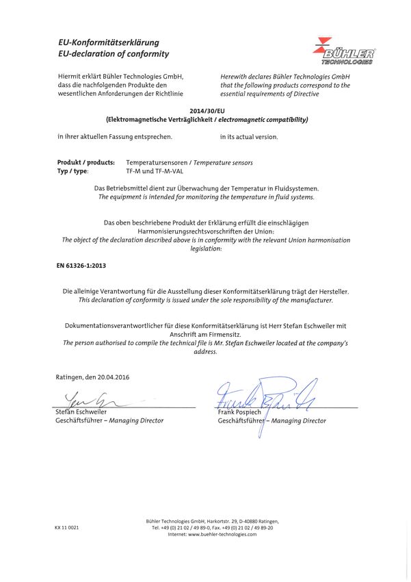
Bühler Technologies GmbH, Harkortstr. 29, D-40880 Ratingen
Tel. +49 (0) 21 02 / 49 89-0, Fax: +49 (0) 21 02 / 49 89-20
Internet: www.buehler-technologies.com
E-Mail: fluidcontrol@buehler-technologies.com

Read this instruction carefully prior to installation and/or use. Pay at-
tention particularly to all advises and safety instructions to prevent in-
juries. Bühler Technologies can not be held responsible for misusing
the product or unreliable function due to unauthorised modifications.

All rights reserved. Bühler Technologies GmbH 2022

Document information
Document No..........................................................BE140006
Version.........................................................................04/2022
TF, TS, Thermolog

Contents
1     Introduction.....................................................................................................................................................................................................................    2
      1.1   Intended Use.........................................................................................................................................................................................................          2
      1.2 Scope of Delivery..................................................................................................................................................................................................              2
      1.3 Model Key MK2/EK2............................................................................................................................................................................................                    2
      1.4 Model Key TF with Pt100 ...................................................................................................................................................................................                      3
      1.5 Ordering Instructions TF-M-VAL with Pt100 and Spring .........................................................................................................................                                                   3
      1.6 Model Key for TSM/TSE......................................................................................................................................................................................                      3
      1.7 Model Key for TSK................................................................................................................................................................................................                4
      1.8 Ordering Instructions TSA ................................................................................................................................................................................                       4
2     Safety instructions......................................................................................................................................................................................................... 5
      2.1 Important advice ................................................................................................................................................................................................. 5
      2.2 General hazard warnings ................................................................................................................................................................................. 6
3     Transport and storage .................................................................................................................................................................................................. 7
4     Setup and Connection .................................................................................................................................................................................................. 8
5     Operation and control .................................................................................................................................................................................................. 9
      5.1 TF-M-Pt100/TF-E-Pt100/TF-M-Pt100-VAL Temperature Sensor ............................................................................................................. 9
      5.2 TSM/TSK/TSA Bi-Metal Temperature Switch .............................................................................................................................................. 9
      5.3 Thermolog MK2/EK2 Temperature Sensor with 4-20mA Output......................................................................................................... 9
6     Maintenance and repair ............................................................................................................................................................................................ 10
7     Service and repair.......................................................................................................................................................................................................... 11
8     Disposal ............................................................................................................................................................................................................................ 12
9     Appendix.......................................................................................................................................................................................................................... 13
      9.1 Technical Data TF with Pt100.......................................................................................................................................................................... 13
      9.2 Technical Data MK2/EK2 .................................................................................................................................................................................. 13
      9.3 Technical Data TF-M-VAL with Pt100 and Spring..................................................................................................................................... 14
      9.4 Technical Data TSM/TSE................................................................................................................................................................................... 15
      9.5 Technical Data TSK............................................................................................................................................................................................. 15
      9.6 Technical Data TSA............................................................................................................................................................................................ 16
      9.7 Standard Pin Assignment TF with Pt100 .................................................................................................................................................... 16
      9.8 Standard Pin Assignment MK2/EK2 ............................................................................................................................................................. 17
      9.9 Standard Pin Assignment TF-M-VAL with Pt100 and Spring................................................................................................................. 17
      9.10 Standard Pin Assignment TSM/TSE ............................................................................................................................................................. 18
      9.11 Standard Pin Assignment TSK ....................................................................................................................................................................... 18
      9.12 Standard Pin Assignment TSA ....................................................................................................................................................................... 19
10 Attached documents ................................................................................................................................................................................................... 20

BE140006 ◦ 04/2022                                                                                                                                                                       Bühler Technologies GmbH                           i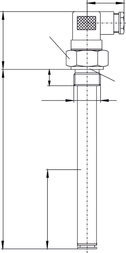
TF, TS, Thermolog

1 Introduction

1.1 Intended Use
Temperature sensors can be used to monitor the temperature of a fluid within a tank.
These operating instructions describe several temperature switches / sensors types in one, as many descriptions identical or
similar.
Please refer to the type plate to identify your model. In addition to the job number it also contains the item number and model
designation.
If a model has special features, these are described separately in the operating instructions.

       WARNING
                       All device models are solely intended for industrial applications. They are not safety com-
                       ponents. The devices must not be used if failure or malfunction thereof jeopardises the
                       safety and health of persons.
                       Use in explosive areas is prohibited.

       DANGER          Explosion hazard when used in explosive areas
                       Use in explosive areas is prohibited.

1.2 Scope of Delivery
– Temperature switch/sensor
– Product documentation

1.3 Model Key MK2/EK2
                                                 XXX - G1/2 - XX - XX / XX

    MK2 for version MS                                                                      Length (max. 1000 mm)
    EK2 for version V                                                                       280
    Version                                                                                 370
    MS Brass                                                                                500
    VA Stainless steel                                                                      variable (please specify)

    Connector
    M3
    M12

2     Bühler Technologies GmbH                                                                                       BE140006 ◦ 04/2022
TF, TS, Thermolog
1.4 Model Key TF with Pt100
XXX - G1/2 - XX - XX - PT100 - XX / XX
TF-M for version MS Length (max. 1000 mm)
TF-E for version V 280
Version 370
MS Brass 500
VA Stainless steel variable (please specify)
Connector Switching type
M3 2L = 2 lead
M12 3L = 3 lead
GS4 (4 lead only) 4L = 4 lead
1.5 Ordering Instructions TF-M-VAL with Pt100 and Spring
Item no.: Spring displacement Model
18 92 599 48 - 60 mm TF-M-PT100-VAL-M3/55
18 94 599 206 - 215 mm TF-M-PT100-VAL-M3/210
18 95 799 325 - 334 mm TF-M-PT100-VAL-M3/330
1.6 Model Key for TSM/TSE
XXX - XX - XX - G1/2 - XX - XX - XX - XX
TSM for Version MS
TSE for Version V
Number of temperature contacts T2 (2nd temperature contact)
1 or 2 NC contact NO contact
Version TM50NC TM50NO = 50 °C
MS Brass TM60NC TM60NO = 60 °C
VA Stainless steel TM70NC TM70NO = 70 °C
TM80NC TM80NO = 80 °C
Connector
M3
M12 T1 (1st temperature contact)
Length (max. 1000 mm) NC contact NO contact
280 TM50NC TM50NO = 50 °C
370 TM60NC TM60NO = 60 °C
500 TM70NC TM70NO = 70 °C
variable (please specify) TM80NC TM80NO = 80 °C
BE140006 ◦ 04/2022 Bühler Technologies GmbH 3TF, TS, Thermolog
1.7 Model Key for TSK
TSK - XX - XX - G3/4 - XX - XX - XX - XX
T2 (2nd temperature contact)
Number of temperature contacts NC contact NO contact
1 or 2 TK40NC TK40NO = 40 °C
Version TK50NC TK50NO = 50 °C
MS Brass TK60NC TK60NO = 60 °C
VA Stainless steel TK70NC TK70NO = 70 °C
TK80NC TK80NO = 80 °C
Connector
M3 T1 (1st temperature contact)
M12
NC contact NO contact
Length (max. 1000 mm) TK40NC TK40NO = 40 °C
280 TK50NC TK50NO = 50 °C
370 TK60NC TK60NO = 60 °C
500 TK70NC TK70NO = 70 °C
variable (please specify) TK80NC TK80NO = 80 °C
1.8 Ordering Instructions TSA
Switching function NO (NO contact) NC (NC contact)
Temperature Model Item no. Model Item no.
25 °C TSA-25-M3 11 39 699 TÖA-25-M3 11 42 899
40 °C TSA-40-M3 11 39 599 TÖA-40-M3 11 43 299
50 °C TSA-50-M3 11 38 599 TÖA-50-M3 11 42 199
60 °C TSA-60-M3 11 38 699 TÖA-60-M3 11 43 399
70 °C TSA-70-M3 11 38 799 TÖA-70-M3 11 40 299
80 °C TSA-80-M3 11 39 299 TÖA-80-M3 11 40 899
4 Bühler Technologies GmbH BE140006 ◦ 04/2022TF, TS, Thermolog
2 Safety instructions
2.1 Important advice
Operation of the device is only permitted if:
– the product is used under the conditions described in the installation- and operation instruction, the intended application
according to the type plate and the intended use. In case of unauthorized modifications done by the user Bühler Technolo-
gies GmbH can not be held responsible for any damage,
– when complying with the specifications and markings on the nameplates.
– the performance limits given in the datasheets and in the installation- and operation instruction are obeyed,
– monitoring devices and safety devices are installed properly,
– service and repair is carried out by Bühler Technologies GmbH,
– only original spare parts are used.
This manual is part of the equipment. The manufacturer keeps the right to modify specifications without advanced notice. Keep
this manual for later use.
Signal words for warnings
Signal word for an imminent danger with high risk, resulting in severe injuries or death if not avoided.
DANGER
Signal word for a hazardous situation with medium risk, possibly resulting in severe injuries or death if not
WARNING
avoided.
Signal word for a hazardous situation with low risk, resulting in damaged to the device or the property or
CAUTION
minor or medium injuries if not avoided.
Signal word for important information to the product.
NOTICE
Warning signs
These instructions use the following warning signs:
Warns of a general hazard Unplug from mains
Voltage warning Wear respiratory equipment
Warns not to inhale toxic gasses Wear a safety mask
Warns of corrosive liquids Wear gloves
General information
BE140006 ◦ 04/2022 Bühler Technologies GmbH 5TF, TS, Thermolog 2.2 General hazard warnings The equipment must be installed by a professional familiar with the safety requirements and risks. Be sure to observe the safety regulations and generally applicable rules of technology relevant for the installation site. Prevent malfunctions and avoid personal injuries and property damage. The operator of the system must ensure: – Safety notices and operating instructions are available and observed, – The respective national accident prevention regulations are observed, – The permissible data and operational conditions are maintained, – Safety guards are used and mandatory maintenance is performed, – Legal regulations are observed during disposal, – compliance with national installation regulations. Maintenance, Repair Please note during maintenance and repairs: – Repairs to the unit must be performed by Bühler authorised personnel. – Only perform conversion-, maintenance or installation work described in these operating and installation instructions. – Always use genuine spare parts. – Do not install damaged or defective spare part. If necessary, visually inspect prior to installation to determine any obvious damage to the spare parts. Always observe the applicable safety and operating regulations in the respective country of use when performing any type of maintenance. 6 Bühler Technologies GmbH BE140006 ◦ 04/2022
TF, TS, Thermolog

3 Transport and storage
Only transport the product inside the original packaging or a suitable alternative.
The equipment must be protected from moisture and heat when not in use. It must be stored in a covered, dry, dust-free room
at room temperature.

BE140006 ◦ 04/2022                                                                               Bühler Technologies GmbH     7
TF, TS, Thermolog

4 Setup and Connection
      DANGER          Toxic, corrosive gasses
                      The sample gas can be harmful to the health if inhaled or on contact.
                      a) Ensure harmful gases are discharged safely.
                      b) Switch off the gas supply before performing maintenance and repairs, and flush the
                         gas lines with air. Secure the gas supply from accidentally being opened.
                      c) Protect yourself from toxic / corrosive gasses when performing maintenance. Wear
                         suitable protective equipment.

The temperature switch / sensor come complete and can be screwed onto the container with the thread. The maximum torque
of the screw-in thread is 25 Nm.
When installing, be sure the sealing face is clean and even. Only screw the temperature switch / sensor into the fitted thread.
Sealed with an elastic sealing ring. No other sealants required.

8    Bühler Technologies GmbH                                                                                   BE140006 ◦ 04/2022
TF, TS, Thermolog
5 Operation and control
DANGER Electric voltage
Risk of electric shock
a) Disconnect the unit from the mains when performing any maintenance.
b) Secure the equipment from accidental restarting.
c) The unit may only be maintained and opened by instructed, competent personnel.
The pin assignment for the respective models are listed in chapter Pin Assignment.
5.1 TF-M-Pt100/TF-E-Pt100/TF-M-Pt100-VAL Temperature Sensor
Type TF temperature sensors use a Pt100 temperature sensor per DIN/IEC 751 class B to generate a temperature-dependent res-
istance signal. The Pt100 sensor is installed at the lowest point of the sensor tube to always ensure sufficient contact with the
medium being measured.
The temperature sensor TF-M-Pt100-VAL was designed for measuring storage temperatures and has a spring-loaded sensor
tube to allow installation free of play with a constant contact pressure at the measuring point.
5.2 TSM/TSK/TSA Bi-Metal Temperature Switch
The TS temperature sensors have a bi-metal temperature switch to signal a set temperature value. Unlike the TSM standard ver-
sion, the TSK and TSA versions with bi-metal switches have a lower hysteresis.
The TSA version is further specifically designed for installation in tube systems and cooling matrices.
The bi-metal switch is installed at the lowest point of the sensor tube to always ensure sufficient contact with the medium be-
ing measured.
5.3 Thermolog MK2/EK2 Temperature Sensor with 4-20mA Output
Type MK2 and EK2 temperature sensors use a Pt100 temperature sensor per DIN EN/IEC 60751 Class B to generate a temperat-
ure-dependent resistance signal.
The built-in electronics convert this resistance signal into a standard 4-20 mA two-lead signal.
The Pt100 sensor is installed at the lowest point of the sensor tube to always ensure sufficient contact with the medium being
measured.
BE140006 ◦ 04/2022 Bühler Technologies GmbH 9TF, TS, Thermolog
6 Maintenance and repair
NOTICE
Always observe the applicable safety and operating regulations when performing any
type of maintenance.
If the devices are mounted according to the instructions, a maintenance is not necessary.
10 Bühler Technologies GmbH BE140006 ◦ 04/2022TF, TS, Thermolog 7 Service and repair This chapter contains information on troubleshooting and correction should an error occur during operation. Repairs to the unit must be performed by Bühler authorised personnel. Please contact our Service Department with any questions: Tel.: +49-(0)2102-498955 or your agent If the equipment is not functioning properly after correcting any malfunctions and switching on the power, it must be inspected by the manufacturer. Please send the equipment inside suitable packaging to: Bühler Technologies GmbH - Reparatur/Service - Harkortstraße 29 40880 Ratingen Germany Please also attach the completed and signed RMA decontamination statement to the packaging. We will otherwise be unable to process your repair order. You will find the form in the appendix of these instructions, or simply request it by e-mail: service@buehler-technologies.com. BE140006 ◦ 04/2022 Bühler Technologies GmbH 11
TF, TS, Thermolog

8 Disposal
Dispose of parts so as not to endanger the health or environment. Follow the laws in the country of use for disposing of elec-
tronic components and devices during disposal.

12    Bühler Technologies GmbH                                                                                  BE140006 ◦ 04/2022
TF, TS, Thermolog

9 Appendix

9.1 Technical Data TF with Pt100
Temperature probe TF with Pt100                                                                                                  Dimensions
                                TF-M-G1/2                      TF-E-G1/2                                                                              37

Version:                        MS                             VA
Probe material:                 Brass                          1.4571
Max. operating pressure:        5 bar                          10 bar                                             SW 36

                                                                                             62
Connection:                     G1/2                           G1/2
Operating temperatures:         -40 °C to +100 °C
Lengths:                        280, 370, 500 (standard)

                                                                                                                              14
                                                                                                                                                            EOlastic
                                variable to max. 1000 mm                                                                                                    seal
Temperature sensor                                                                                                                                          NBR
                                                                                                                                   G1/2
Sensor element:                 Pt100 Class B DIN EN 60751

                                                                                             L = max. 1000
Tolerance:                      ±0.8 °C
Switching type:                 2, 3 or 4 lead

                                                                                                                  Installation depth
                                                                                                                        min. 50
                                                                                                                                             Ø11

Pt100 measuring resistance base values
    °C          0          10             20           30        40         50       60                      70                         80          90           100
  Ohm         100.00     103.90         107.79        111.67   115.54      119.40   123.24   127.07                         130.89                 134.70       138.50

9.2 Technical Data MK2/EK2
MK2/EK2 with temperature transmitter                                                                                             Dimensions
                                MK2-G1/2                       EK2-G1/2                                                                               37

Version:                        MS                             VA
Probe material:                 Brass                          1.4571
Max. operating pressure:        5 bar                          10 bar                                              SW 36
                                                                                             62

Connection:                     G1/2                           G1/2
Operating temperatures:         -20 °C to +80 °C
Lengths:                        280, 370, 500 (standard)
                                                                                                                              14

                                                                                                                                                            EOlastic
                                variable to max. 1000 mm                                                                                                    seal
Temperature transmitter                                                                                                                                     NBR
                                                                                                                                   G1/2
Sensor element:                 Pt100 Class B DIN EN 60751
                                                                                             L = max. 1000

Tolerance Pt100:                ±0.8 °C
Operating voltage (UB)          10 - 30 VDC
Measuring range*                0 °C to +100 °C
                                                                                                                   Installation depth

Output*                         4 - 20 mA
                                                                                                                         min. 50

Load Ω max.                     (UB - 7.5 V)/0.02 A

                                                                                                                                         Ø11

*Other measuring ranges and outputs available on request.

BE140006 ◦ 04/2022                                                                                                                     Bühler Technologies GmbH          13
TF, TS, Thermolog
9.3 Technical Data TF-M-VAL with Pt100 and Spring
Version with external spring Version with internal spring
Length: L Spring Lengths: L Spring
displacement displacement
55 48 - 60 mm 210 206 - 215 mm
Fastening torque: 25 Nm 330 325 - 334 mm
Probe material: Anodised aluminium/spring steel Probe material: Brass
Seal: NBR Seal: NBR
Max. operating pressure: 1 bar Max. operating pressure: 1 bar
Connection: G1/2 Connection: G1/2
Operating temperature -40 °C to +100 °C Operating temperature: -40°C to +100 °C
36 36
68
68
SW 36 SW 36
with external spring
EOlastic EOlastic
seal
with internal spring
seal
NBR NBR
14
14
48 - 60
G1/2
G1/2
L
ø30
Temperature sensor
Sensor element: Pt100 Class B, DIN EN 60 751
Tolerance: ±0.8 °C
Switching type: 2 lead
Pt100 measuring resistance base values
°C 0 10 20 30 40 50 60 70 80 90 100
Ohm 100.00 103.90 107.79 111.67 115.54 119.40 123.24 127.07 130.89 134.70 138.50
14 Bühler Technologies GmbH BE140006 ◦ 04/2022TF, TS, Thermolog
9.4 Technical Data TSM/TSE
Model TSM-G1/2 TSE-G1/2 Dimensions
Version: MS VA 37
Probe material: Brass 1.4571
Max. operating pressure: 5 bar 10 bar
Connection: G1/2 G1/2
SW 36
Operating temperatures: -40 °C to +80 °C
62
Lengths: 280, 370, 500 (standard)
variable to max. 1000 mm
Temperature contact TMxx
14
Switch element: Bi-metal EOlastic
seal
Number of contacts: 1 or 2 NBR
G1/2
Max. voltage: 230 V
Max. switching current: 2A
L = max. 1000
Max. contact load: 100 VA
Function NC* NO*
(min. 80 with 2 x TM)
Switching point °C: 50/60/70/80 50/60/70/80
Immersion depth
Switching point tolerance: ± 5 K ±5K
min. 50
Max. hysteresis: 18 K ± 5 K 26/35/40/45 K ± 5 K
Other temperatures available upon request
* NC = NC contact/NO = NO contact (all data for rising temperature)
9.5 Technical Data TSK
Model TSK-G3/4 Dimensions
Version: MS VA 37
Probe material: Brass 1.4571
Max. operating pressure: 1 bar 5 bar
SW 36
Connection: G3/4 G3/4
62
Operating temperatures: -40 °C to +80 °C
Lengths: 280, 370, 500 (standard)
variable to max. 1000 mm
16
EOlastic
Temperature contact TKxx G3/4 seal
NBR
Switch element: Bi-metal
Number of contacts: 1 or 2
Max. voltage: 230 V
L = max. 1000
Max. switching current: 2A
Max. contact load: 100 VA
Function NC*/NO*
(min. 120 with 2 x TK)
Immersion depth
Switching point °C: 40/50/60/70/80
min. 50
Switching point tolerance: ± 3 K
Max. hysteresis: 10 K ± 5 K
Other temperatures available upon request
* NC = NC contact/NO = NO contact (all data for rising temperature)
BE140006 ◦ 04/2022 Bühler Technologies GmbH 15TF, TS, Thermolog
9.6 Technical Data TSA
Model TSA Dimensions
Probe length: 29 mm 37
Probe material: Anodised aluminium
Max. operating pressure: 15 bars
Operating temperatures: -40 °C to +80 °C
Temperature contacts SW 36
62
Switch element: Bi-metal
Max. voltage: 230 V
Max. switching current: 2A
Max. contact load: 100 VA
14
EOlastic
29
Tolerance: ±5K seal
Switch-back difference: 15 K ± 3 K NBR
G1/2
Function NC*/NO*
Switching point °C: 25/40/50/60/70/80
Other temperatures available upon request
* NC = NC contact/NO = NO contact (all data for rising temperature)
9.7 Standard Pin Assignment TF with Pt100
Connector: M3 valve connector GS4 M12 plug A coded
Dimensions:
Number of pins: 3-pin + PE 4-pin 4-pin
DIN EN: 175301-803 61076-2-101
IP rating: IP65 IP65 IP67**
Cable fitting: PG 11 PG 7
Standard pin assignment:
2 lead ---
3 lead ---
4 lead ---
**with IP67 cable box screwed on
Other connectors available on request
16 Bühler Technologies GmbH BE140006 ◦ 04/2022TF, TS, Thermolog 9.8 Standard Pin Assignment MK2/EK2 Connector: M3 valve connector M12 plug A coded Dimensions: Number of pins: 3-pin + PE 4-pin DIN EN: 175301-803 61076-2-101 Voltage max. 30 V DC 30 V DC IP rating: IP65 IP67** Cable fitting: PG 11 Standard pin assignment: **with IP67 cable box screwed on Other connectors available on request 9.9 Standard Pin Assignment TF-M-VAL with Pt100 and Spring Connector: M3 valve connector Dimensions: Number of pins: 3-pin + PE DIN EN: 175301-803 IP rating: IP65 Cable fitting: PG 11 Standard pin assignment: 2 lead BE140006 ◦ 04/2022 Bühler Technologies GmbH 17
TF, TS, Thermolog

9.10 Standard Pin Assignment TSM/TSE
Plug connection*:                         M3 valve connector         M12 plug A coded
Dimensions:

Connection schematic:                                  3

                                               2                 1

                                                      PE
Number of pins:                                     3-pin + PE            4-pin
DIN EN:                                            175301-803          61076-2-101
Max. voltage:                                      230 V AC/DC           30 V DC
IP rating:                                            IP 65               IP 67*
Cable fitting:                                        PG 11
Standard pin assignment:

T1 = lower temperature/T2 upper temperature.
* other connectors available on request.
** with IP67 cable box screwed on.

9.11 Standard Pin Assignment TSK
Plug connection*:                         M3 valve connector         M12 plug A coded
Dimensions:

Connection schematic:                                  3

                                               2                 1

                                                      PE
Number of pins:                                     3-pin + PE            4-pin
DIN EN:                                            175301-803          61076-2-101
Max. voltage:                                      230 V AC/DC           30 V DC
IP rating:                                            IP 65               IP 67*
Cable fitting:                                        PG 11
Standard pin assignment:

T1 = lower temperature/T2 upper temperature.
* other connectors available on request.
** with IP67 cable box screwed on.

18    Bühler Technologies GmbH                                                       BE140006 ◦ 04/2022
TF, TS, Thermolog
9.12 Standard Pin Assignment TSA
Plug connection*: M3 valve connector
Dimensions:
Connection schematic: 3
2 1
PE
Number of pins: 3-pin + PE
DIN EN: 175301-803
Max. voltage: 230 V AC/DC
IP rating: IP 65
Cable fitting: PG 11
Standard pin assignment:
* other connectors available on request.
BE140006 ◦ 04/2022 Bühler Technologies GmbH 19TF, TS, Thermolog 10 Attached documents – Declarations of conformity: KX140002, KX110021 – RMA decontamination statement 20 Bühler Technologies GmbH BE140006 ◦ 04/2022
RMA-Formular und Erklärung über Dekontaminierung
RMA-Form and explanation for decontamination
RMA-Nr./ RMA-No.
Die RMA-Nummer bekommen Sie von Ihrem Ansprechpartner im Vertrieb oder Service./ You may obtain the RMA
number from your sales or service representative.
Zu diesem Rücksendeschein gehört eine Dekontaminierungserklärung. Die gesetzlichen Vorschriften schreiben vor,
dass Sie uns diese Dekontaminierungserklärung ausgefüllt und unterschrieben zurücksenden müssen. Bitte füllen Sie
auch diese im Sinne der Gesundheit unserer Mitarbeiter vollständig aus./ This return form includes a decontamination
statement. The law requires you to submit this completed and signed decontamination statement to us. Please com-
plete the entire form, also in the interest of our employee health.

Firma/ Company                                                                       Ansprechpartner/ Person in charge

Firma/ Company                                                                       Name/ Name
Straße/ Street                                                                       Abt./ Dept.
PLZ, Ort/ Zip, City                                                                  Tel./ Phone
Land/ Country                                                                        E-Mail

Gerät/ Device                                                                        Serien-Nr./ Serial No.

Anzahl/ Quantity                                                                     Artikel-Nr./ Item No.

Auftragsnr./ Order No.
Grund der Rücksendung/ Reason for return                                        bitte spezifizieren/ please specify

    Kalibrierung/ Calibration                Modifikation/ Modification
    Reklamation/ Claim                       Reparatur/ Repair
    andere/ other
Ist das Gerät möglicherweise kontaminiert?/ Could the equipment be contaminated?
   Nein, da das Gerät nicht mit gesundheitsgefährdenden Stoffen betrieben wurde./ No, because the device was not operated with
hazardous substances.
   Nein, da das Gerät ordnungsgemäß gereinigt und dekontaminiert wurde./ No, because the device has been properly cleaned and
decontaminated.
  Ja, kontaminiert mit:/ Yes, contaminated with:

       explosiv/      entzündlich/    brandfördernd/   komprimierte        ätzend/           giftig,      gesundheitsge-       gesund-         umweltge-
       explosive       flammable         oxidizing       Gase/             caustic      Lebensgefahr/       fährdend/      heitsschädlich/     fährdend/
                                                       compressed                       poisonous, risk     harmful to      health hazard    environmental
                                                          gases                            of death           health                             hazard
Bitte Sicherheitsdatenblatt beilegen!/ Please enclose safety data sheet!

Das Gerät wurde gespült mit:/ The equipment was purged with:
Diese Erklärung wurde korrekt und vollständig ausgefüllt und von einer          This declaration has been filled out correctly and completely, and signed by
dazu befugten Person unterschrieben. Der Versand der (dekontaminier-            an authorized person. The dispatch of the (decontaminated) devices and
ten) Geräte und Komponenten erfolgt gemäß den gesetzlichen Bestim-              components takes place according to the legal regulations.
mungen.

Falls die Ware nicht gereinigt, also kontaminiert bei uns eintrifft, muss die   Should the goods not arrive clean, but contaminated, Bühler reserves the
Firma Bühler sich vorbehalten, diese durch einen externen Dienstleister         right, to comission an external service provider to clean the goods and in-
reinigen zu lassen und Ihnen dies in Rechnung zu stellen.                       voice it to your account.

Firmenstempel/ Company Sign                                                     Datum/ Date

                                                                                rechtsverbindliche Unterschrift/ Legally binding signature

DE000011                                       Bühler Technologies GmbH, Harkortstr. 29, D-40880 Ratingen
01/2019                                         Tel. +49 (0) 21 02 / 49 89-0, Fax: +49 (0) 21 02 / 49 89-20
                                                        E-Mail: service@buehler-technologies.com
                                                         Internet: www.buehler-technologies.com
Dekontaminierungserklärung
Die Analyse defekter Baugruppen ist ein wesentlicher Bestandteil der Qualitätssicherung der Firma
Bühler Technologies.
Um eine aussagekräftige Analyse zu gewährleisten muss die Ware möglichst unverändert untersucht
werden. Es dürfen keine Veränderungen oder weitere Beschädigungen auftreten, die Ursachen ver-
decken oder eine Analyse unmöglich machen.
Bei elektronischen Baugruppen kann es sich um elektrostatisch sensible Baugruppen handeln. Es ist
darauf zu achten, diese Baugruppen ESD-gerecht zu behandeln. Nach Möglichkeit sollten die Baugrup-
pen an einem ESD-gerechten Arbeitsplatz getauscht werden. Ist dies nicht möglich sollten ESD-
gerechte Maßnahmen beim Austausch getroffen werden. Der Transport darf nur in ESD-gerechten Be-
hältnissen durchgeführt werden. Die Verpackung der Baugruppen muss ESD-konform sein. Verwenden
Sie nach Möglichkeit die Verpackung des Ersatzteils oder wählen Sie selber eine ESD-gerechte Ver-
packung.
Beachten Sie beim Einbau des Ersatzteils die gleichen Vorgaben wie oben beschrieben. Achten Sie auf
die ordnungsgemäße Montage des Bauteils und aller Komponenten. Versetzen Sie vor der Inbetrieb-
nahme die Verkabelung wieder in den ursprünglichen Zustand. Fragen Sie im Zweifel beim Hersteller
nach weiteren Informationen.
Analysing defective assemblies is an essential part of quality assurance at Bühler Technologies.
To ensure conclusive analysis the goods must be inspected unaltered, if possible. Modifications or
other damages which may hide the cause or render it impossible to analyse are prohibited.
Electronic assemblies may be sensitive to static electricity. Be sure to handle these assemblies in an
ESD-safe manner. Where possible, the assembles should be replaced in an ESD-safe location. If un-
able to do so, take ESD-safe precautions when replacing these. Must be transported in ESD-safe con-
tainers. The packaging of the assemblies must be ESD-safe. If possible, use the packaging of the spare
part or use ESD-safe packaging.
Observe the above specifications when installing the spare part. Ensure the part and all components
are properly installed. Return the cables to the original state before putting into service. When in doubt,
contact the manufacturer for additional information.
DE000011 Bühler Technologies GmbH, Harkortstr. 29, D-40880 Ratingen
01/2019 Tel. +49 (0) 21 02 / 49 89-0, Fax: +49 (0) 21 02 / 49 89-20
E-Mail: service@buehler-technologies.com
Internet: www.buehler-technologies.comYou can also read