Strain Probe DSRK - EN DE IT - Baumer
←
→
Page content transcription
If your browser does not render page correctly, please read the page content below
Force and strain sensors
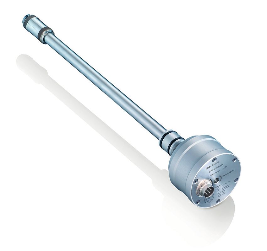
Strain Probe DSRK
Simple strain measurement in deep holes
EN Operating Instructions 3
DE Betriebsanleitung 11
IT Istruzioni di funzionamento 19Force and strain sensors
Strain Probe DSRK
Simple strain measurement in deep holes
Type plate
1 1 Material number
2 2 Type of sensor
11177645
DSRK U16-0320M
2.17.101682346.1 3 3 Ordering number
4 Production code
-Swiss made- J062
45 20
M
76 6-0346.1 62
1117 U16823 J0
4
5 Mounting torque
RK
DS .101 ade-
2.17 ss m Torque 16 Nm
5
wi
-S Nm
e 12
qu
Tor
C)
VD
: -33 nect
ion s (18 con
cat +V T lar)
allo 1 NO po )
Pin allocation:
6 Pin assignment
Pin Pin Do set (bi polar
Pin 1 +Vs (18-33 VDC)
6
1 (bi V)
Pin 1 Re set -10
(+/
Pin 1 Reout
Pin 1 +V ut
Pin 1 Do NOT connect
Pin 1 -Vo D
4
Pin 1 GN 3 4 Pin 1 Reset (bipolar)
3 7 5 Pin 7 Pin 1 Reset (bipolar)
2 6
1 2 5
1 6 Pin 1 +Vout (+/-10V)
Pin 1 -Vout
Do not dispose of in household waste
Pin 1 GND
Conformity with EU directives
Permissions, customer-specific
1 Materialnummer 1 Codice materiale
2 Sensortyp 2 Tipo di sensore
3 Auftragsnummer 3 Numero d’ordine
4 Produktionscode 4 Codice produzione
5 Anzugsmoment 5 Coppia di serraggio
6 Pin-Belegung 6 Occupazione pin
Nicht im Hausmüll entsorgen Non gettare tra i rifiuti domestici
Konformität mit EU-Richtlinien Conformità con le direttive UE
Zulassung Underwriters Labratories Omologazione Underwriters
(UL) Laboratories (UL)
2 / 28 Operating Instructions www.baumer.comForce and strain sensors
Strain Probe DSRK
Simple strain measurement in deep holes
Table of contents
1. Safety........................................................... 3 9. Electrical connection.................................... 7
2. Construction and function............................ 3 10. Operation .................................................... 8
3. Type of sensor.............................................. 3 11. Dismantling................................................... 8
4. Compatibility................................................. 4 12. Troubleshooting dismantling......................... 8
5. Symbols in warning signs............................. 4 13. Maintenance and repair................................ 9
6. Transport and storage.................................. 4 14. Disposal....................................................... 9
7. Preparing for assembly................................ 4 15. Accessories.................................................. 9
8. Troubleshooting assembly............................ 6 16. Technical data.............................................. 9
1. Safety
Intended use Make sure that the staff have read and understood
The strain probe must be used solely for measuring these instructions.
strains on machine elements. Technical condition
Staff qualification Only use strain probe in perfect technical
Only use staff who are trained for the activities condition. Only use Baumer accessories. Baumer
described. This applies particularly to assembly will accept no liability for other manufacturers’
and electrical connection. accessories.
2. Construction and function
The strain of the machine element is picked up on
2 3 4 5
the inner wall of a hole via clamping collars (8) and
scanning surfaces (7) and transmitted to strain
1 measuring strips. These strain measuring strips
are glued into the measuring head. Depending
7 on the strain an electrical signal is generated that
6 is converted into a standardized output signal
8 within the housing (6). The scanning point for the
measurement can be optimally selected using
tubes of different lengths (2).
Fig. 1. Construction
5 Hexagon socket SW 6
1 Measuring head 6 Housing
2 Pipe 7 Scanning surfaces
3 Supporting ring (DSRK x20 only) 8 Clamping collars
4 Connector, 7 pin
3. Type of sensor
1 Output signal U or I
DSRK U16-0320M 2 Measuring head diameter in mm
1 2 3 3 Measuring point depth in mm
Fig. 2. Example of sensor type
www.baumer.com Operating Instructions 3 / 28Force and strain sensors
Strain Probe DSRK
Simple strain measurement in deep holes
4. Compatibility
The DSRK strain probe is fully compatible with For installation notes see Page 5.
older strain probes in the DSRH series.
5. Symbols in warning signs
Symbol Warning term Explanation
DANGER In situations which cause death or serious injuries.
WARNING In situations which can cause death or serious injuries.
CAUTION In situations which can cause light or medium injuries.
ATTENTION For material damage
6. Transport and storage
f ATTENTION! Function errors via contaminated f In the event of damage: Do not use strain probe.
measuring head. Do not touch scanning f Transport or store strain probe only in original
surfaces on the measuring head with bare packaging.
hands. Follow safety instructions on the f Store strain probe where it will be secure against
packaging. shock.
f Check packaging and strain probe for damage. Storage temperature: -40 ... +85 °C
Relative humidity: < 98 %
7. Preparing for assembly
ø DS
Prepare bore in the machine element or strut.
ø DT
f
Length of hole: LM + 30 mm
Roughness: ra = 3.2 μm
Diameter precision at hole end: 0/+0.35 mm
LS > 1.5 x DT ~ 10
LM
Min. 10 LM + 30
Fig. 3. Hole in the machine element
LM Depth of measuring point
Ø DS Measuring head diameter
Ø DT Outer diemeter tie bar
LS Measurement position Measurement position; ideal depth 1.5 … 2 times
tie bar diameter (steady cross section)
4 / 28 Operating Instructions www.baumer.comForce and strain sensors
Strain Probe DSRK
Simple strain measurement in deep holes
7.1 Assembly
ATTENTION
False measurement results via contaminated measuring head or incorrect assembly
f Avoid contamination from grease or oil.
f Do not touch scanning surfaces on the measuring head with bare hands.
f The machine element must not touch the strain probe housing after assembly.
1 9 Hole must be prepared.
f Carefully take strain probe out of the packaging.
When doing so, follow safety instructions on the
packaging.
2 10 mm f Insert strain probe into the hole with a slow
continuous movement.
f Insert strain probe so far that 10mm of the tube
of the probe remains visible.
3 f Turn sensor housing in clockwise until back
pressure becomes noticeable.
4 f ATTENTION! Excessive tightening torque can
damage the measuring head. Keep precisely to
the specified tightening torque.
f Tension strain probe with torque wrench
(hexagon socket SW6).
Tightening torque: 16 Nm.
www.baumer.com Operating Instructions 5 / 28Force and strain sensors
Strain Probe DSRK
Simple strain measurement in deep holes
8. Troubleshooting assembly
Problem Cause Action
Strain probe cannot be Tensioning mechanism is f ATTENTION! Measuring error via contaminated
fully inserted into the not fully relaxed. measuring head. Do not touch scanning
hole. surfaces on the measuring head with bare
hands.
f Take the measuring head between the scanning
surfaces and carefully rotate a half to a full turn.
f Insert strain probe into the hole again.
Strain probe cannot be Clamping collars do not f Remove strain probe from the hole.
clamped. extend. f ATTENTION! Measuring error via contaminated
measuring head. Do not touch scanning
surfaces on the measuring head with bare
hands.
f Take the measuring head between the scanning
surfaces and carefully rotate a quarter to a half
turn.
The clamping collars will come apart.
6 / 28 Operating Instructions www.baumer.comForce and strain sensors
Strain Probe DSRK
Simple strain measurement in deep holes
9. Electrical connection
9 A voltage supply of 18 V to 33 V DC is provided. Terminal assignment
(Power supply according to UL 1310, Class 2 or external
protection via a UL-approved or listed fuse with max. 100 W/ 3 4
7
Vp or max. 5 A below 20 V.) 2 5
1 6
f Switch off supply voltage.
f Connect strain probe in accordance with pin assignment or
cable color.
Reset DSRK Uxx equivalent circuits 7 pin Cable color
Electri- 1 White
cally 1 +V S 2 Brown
18 - 36 VDC
isolated 2 do not connect 3 Green
3 Reset (bipolar ) Reset switch
Reset (bipolar ) 15 - 45 VDC 4 Yellow
4
5 +V OUT 5 Grey
±10 V
RL
6 -VOUT 6 Blue
7 GND
7 Pink
Non-elec- 1 White
trically 1 +V S
18 - 36 VDC 2 Brown
isolated 2 do not connect
3 Reset (bipolar)
3 Green
4 Reset (bipolar) Reset switch 4 Yellow
5 +V OUT
RL
± 10 V 5 Grey
6 -VOUT
7 GND
6 Blue
7 Pink
Reset DSRK Ixx equivalent circuits 7 pin Cable color
Electri- 1 White
cally 1 +V S 2 Brown
18 - 36 VDC
isolated 2 do not connect 3 Green
3 Reset (bipolar ) Reset switch
Reset (bipolar ) 15 - 45 VDC 4 Yellow
4
5 I OUT 5 Grey
4 - 20 mA
RL
6 OUT 6 Blue
7 GND
7 Pink
Non-elec- 1 White
trically 1 +V S
18 - 36 VDC 2 Brown
isolated 2 do not connect
3 Reset (bipolar)
3 Green
4 Reset (bipolar) Reset switch 4 Yellow
5 I OUT
RL
4 - 20 mA 5 Grey
6 OUT
7 GND
6 Blue
7 Pink
www.baumer.com Operating Instructions 7 / 28Force and strain sensors
Strain Probe DSRK
Simple strain measurement in deep holes
10. Operation
To avoid measuring errors due to temperature
changes, Baumer recommends calibrating the
strain probe’s output signal after each machine
cycle. This sets the output signal to zero.
t
U
Reset
t1 t2
t
Fig. 4. Reset
Vout /IOUT Output signal t2 Waiting time for receiving new measurement
t1 Reset pulse (> 1 ms) signal (> 15 ms)
11. Dismantling
f ATTENTION! Damage to strain probe. Dismantle
and reuse a maximum of 3 times.
f Disconnect strain probe from the power supply.
f Turn housing in counter-clockwise direction.
When doing so a higher torque is necessary at
the start to loosen the measuring head.
f Turn housing approximately 3 full turns.
f Pull strain probe out of the hole with a light tug.
12. Troubleshooting dismantling
Problem Cause Action
Strain probe cannot be Scanning surfaces of the f Lightly hit the housing with a rubber mallet until
pulled out. tensioning mechanism are the scanning surfaces loosen.
wedged.
8 / 28 Operating Instructions www.baumer.comForce and strain sensors
Strain Probe DSRK
Simple strain measurement in deep holes
13. Maintenance and repair
Maintenance Repair
Regular maintenance is not required. Do not repair the strain probe yourself.
f Send damaged strain probe to Baumer.
14. Disposal
f Do not dispose of in household
waste.
f Separate materials and dispose
of in compliance with nationally
applicable regulations.
15. Accessories
For accessories see www.baumer.com.
16. Technical data
Environmental conditions Electrical data
Operating temperature -5 ... +85 °C Measurement range 0 ... 1000 µε
range
Storage temperature range -40 ... +85 °C Reset input 15 ... 45 V DC
Relative humidity < 98% Reset active > ±15 V DC
Protection class IP54 Reset inactive < ±5 V DC
Reset pulse > 1 ms
Power supply Connection
Voltage supply range 18 ... 33 V DC Connector Binder type, series
680/SGR 70, 7-pin
Current consumption < 50 mA (DSRK U)
< 50 mA (DSRK I)
www.baumer.com Operating Instructions 9 / 28Force and strain sensors
Strain Probe DSRK
Simple strain measurement in deep holes
10 / 28 Operating Instructions www.baumer.comKraft- und Dehnungssensoren
Messlanze DSRK
Einfache Dehnungsmessung in tiefen Bohrungen
Inhaltsverzeichnis
1. Sicherheit....................................................11 9. Elektrischer Anschluss................................15
2. Aufbau und Funktion...................................11 10. Betrieb ....................................................... 16
3. Sensortyp....................................................11 11. Demontage................................................. 16
4. Kompatibilität...............................................12 12. Problembehebung bei Demontage............ 16
5. Symbole in Warnhinweisen.........................12 13. Wartung und Reparatur...............................17
6. Transport und Lagerung..............................12 14. Entsorgung..................................................17
7. Montage vorbereiten...................................12 15. Zubehör.......................................................17
8. Problembehebung bei Montage..................14 16. Technische Daten........................................17
1. Sicherheit
Bestimmungsgemässe Verwendung Sicherstellen, dass das Personal diese Anleitung
Die Messlanze darf ausschliesslich zur Messung gelesen und verstanden hat.
von Dehnungen an Maschinenelementen Technischer Zustand
verwendet werden. Messlanze nur in einwandfreiem technischem
Personalqualifikation Zustand verwenden. Nur Zubehör von Baumer
Nur Personal einsetzen, das für die beschriebenen verwenden. Für Zubehör anderer Hersteller
Tätigkeiten geschult ist. Dies gilt insbesondere für übernimmt Baumer keine Haftung.
Montage und elektrischen Anschluss.
2. Aufbau und Funktion
Über Spannschalen (8) und Abgriffflächen (7)
2 3 4 5
wird die Dehnung des Maschinenelements an
der Innenwand einer Bohrung abgegriffen und
1 auf Dehnungsmessstreifen übertragen. Diese
Dehnungsmessstreifen sind in den Messkopf
7 eingeklebt. Abhängig von der Dehnung wird ein
6 elektrisches Signal erzeugt, das im Gehäuse (6)
8 in ein standardisiertes Ausgangssignal gewandelt
wird. Durch verschieden lange Rohre (2) kann
der Abgriffpunkt für die Messung optimal gewählt
Abb. 1. Aufbau werden.
1 Messkopf 5 Innensechskant SW 6
2 Rohr 6 Gehäuse
3 Stützring (nur DSRK x20) 7 Abgriffflächen
4 Anschlussstecker, 7 Pin 8 Spannschalen
3. Sensortyp
1 Ausgangssignal U oder I
DSRK U16-0320M 2 Durchmesser Messkopf in mm
1 2 3 3 Messpunkttiefe in mm
Abb. 2. Beispiel für Sensortyp
www.baumer.com Betriebsanleitung 11 / 28Kraft- und Dehnungssensoren
Messlanze DSRK
Einfache Dehnungsmessung in tiefen Bohrungen
4. Kompatibilität
Die Messlanze DSRK ist vollständig kompatibel zu Montagehinweise siehe Seite 13.
älteren Messlanzen der Baureihe DSRH.
5. Symbole in Warnhinweisen
Symbol Warnwort Erklärung
GEFAHR Bei Situationen, die zum Tod oder zu schweren Verletzungen führen.
WARNUNG Bei Situationen, die zum Tod oder zu schweren Verletzungen führen können.
VORSICHT Bei Situationen, die zu leichten oder mittelschweren Verletzungen führen
können.
ACHTUNG Bei Sachschäden
6. Transport und Lagerung
f ACHTUNG! Funktionsstörungen durch f Bei Beschädigung: Messlanze nicht verwenden.
verschmutzten Messkopf. Abgriffflächen am f Messlanze nur in Originalverpackung
Messkopf nicht mit den Händen berühren. transportieren oder lagern.
Hinweise auf der Verpackung beachten. f Messlanze stosssicher lagern.
f Verpackung und Messlanze auf Beschädigungen Lagertemperatur: -40 ... +85 °C
prüfen. Relative Luftfeuchtigkeit: 1.5 x DT ~ 10
LM
Min. 10 LM + 30
Abb. 3. Bohrung im Maschinenelement
LM Messpunkttiefe
Ø DS Durchmesser Messkopf
Ø DT Durchmesser Holm
LS Messposition Messposition ideal 1.5 ... 2 mal Holmdurchmesser
tief in gleichförmigem Querschnitt
12 / 28 Betriebsanleitung www.baumer.comKraft- und Dehnungssensoren
Messlanze DSRK
Einfache Dehnungsmessung in tiefen Bohrungen
7.1 Montage
ACHTUNG
Falsche Messergebnisse durch verschmutzen Messkopf oder falsche Montage
f Verschmutzungen durch Fett oder Öl vermeiden.
f Abgriffflächen am Messkopf nicht mit den Händen berühren.
f Gehäuse der Messlanze darf das Maschinenelement nach der Montage nicht berühren.
1 9 Bohrloch ist vorbereitet.
f Messlanze vorsichtig aus der Verpackung
nehmen. Dabei Hinweise auf der Verpackung
beachten.
2 10 mm f Messlanze mit einer langsamen, kontinuierlichen
Bewegung in das Bohrloch einführen.
f Messlanze so weit einführen, dass das Rohr der
Messlanze 10 mm sichtbar bleibt.
3 f Gehäuse des Sensors im Uhrzeigersinn drehen,
bis Gegendruck spürbar wird.
4 f ACHTUNG! Beschädigung des Messkopfs durch
zu grosses Anzugsmoment. Angegebenes
Anzugsmoment genau einhalten.
f Messlanze mit Drehmomentschlüssel
(Innensechskant SW6) spannen.
Anzugsmoment: 16 Nm.
www.baumer.com Betriebsanleitung 13 / 28Kraft- und Dehnungssensoren
Messlanze DSRK
Einfache Dehnungsmessung in tiefen Bohrungen
8. Problembehebung bei Montage
Problem Ursache Massnahme
Messlanze kann nicht Spannmechanismus ist f ACHTUNG! Messfehler durch verschmutzten
vollständig in die Boh- nicht vollständig entspannt. Messkopf. Abgriffflächen am Messkopf nicht mit
rung einführt werden. den Händen berühren.
f Messkopf zwischen den Abgriffflächen fassen
und vorsichtig eine halbe bis eine ganze
Umdrehung drehen.
f Messlanze erneut in die Bohrung einführen.
Messlanze lässt sich Spannschalen fahren nicht f Messlanze aus der Bohrung herausziehen.
nicht verspannen. aus. f ACHTUNG! Messfehler durch verschmutzten
Messkopf. Abgriffflächen am Messkopf nicht mit
den Händen berühren.
f Messkopf zwischen den Abgriffflächen fassen
und um eine viertel oder halbe Umdrehung
drehen.
Die Spannschalen fahren etwas auseinander.
14 / 28 Betriebsanleitung www.baumer.comKraft- und Dehnungssensoren
Messlanze DSRK
Einfache Dehnungsmessung in tiefen Bohrungen
9. Elektrischer Anschluss
9 Betriebsspannung 18 V bis 33 V DC ist bereitgestellt. Anschlussbelegung
(Netzteil nach UL 1310, Class 2 oder externe Absicherung durch eine
UL anerkannte oder gelistete Sicherung mit max.100 W/Vp oder max. 3 4
7
5 A unter 20 V.) 2 5
1 6
f Betriebsspannung ausschalten.
f Messlanze laut Pin-Belegung oder Kabelfarbe anschliessen.
Reset Ersatzschaltbilder DSRK Uxx 7 Pin Kabelfarbe
Galva- 1 Weiss
nisch 1 +V S 2 Braun
18 - 36 VDC
getrennt 2 do not connect 3 Grün
3 Reset (bipolar ) Reset switch
Reset (bipolar ) 15 - 45 VDC 4 Gelb
4
5 +V OUT 5 Grau
±10 V
RL
6 -VOUT 6 Blau
7 GND
7 Rosa
Nicht gal- 1 Weiss
vanisch 1 +V S
18 - 36 VDC 2 Braun
getrennt 2 do not connect
3 Reset (bipolar)
3 Grün
4 Reset (bipolar) Reset switch 4 Gelb
5 +V OUT
RL
± 10 V 5 Grau
6 -VOUT
7 GND
6 Blau
7 Rosa
Reset Ersatzschaltbilder DSRK Ixx 7 Pin Kabelfarbe
Galva- 1 Weiss
nisch 1 +V S 2 Braun
18 - 36 VDC
getrennt 2 do not connect 3 Grün
3 Reset (bipolar ) Reset switch
Reset (bipolar ) 15 - 45 VDC 4 Gelb
4
5 I OUT 5 Grau
4 - 20 mA
RL
6 OUT 6 Blau
7 GND
7 Rosa
Nicht gal- 1 Weiss
vanisch 1 +V S
18 - 36 VDC 2 Braun
getrennt 2 do not connect
3 Reset (bipolar)
3 Grün
4 Reset (bipolar) Reset switch 4 Gelb
5 I OUT
RL
4 - 20 mA 5 Grau
6 OUT
7 GND
6 Blau
7 Rosa
www.baumer.com Betriebsanleitung 15 / 28Kraft- und Dehnungssensoren
Messlanze DSRK
Einfache Dehnungsmessung in tiefen Bohrungen
10. Betrieb
Um Messfehler durch Temperaturänderungen zu
vermeiden, empfiehlt Baumer das Ausgangssignal
der Messlanze nach jedem Maschinenzyklus neu
zu tarieren. Damit wird das Ausgangssignal auf
Null gesetzt.
t
U
Reset
t1 t2
t
Abb. 4. Reset
Vout /IOUT Ausgangssignal t2 Wartezeit für Empfang neues Messsignal
t1 Reset-Puls (> 1 ms) (> 15 ms)
11. Demontage
f ACHTUNG! Beschädigung der Messlanze.
Maximal 3 Mal demontieren und
wiederverwenden.
f Messlanze von der Spannungsversorgung
trennen.
f Gehäuse im Gegenuhrzeigersinn drehen.
Dabei ist zu Beginn ein höheres Drehmoment
notwendig, um den Messkopf zu lösen.
f Gehäuse ungefähr 3 volle Umdrehungen drehen.
f Messlanze mit einem leichten Zug aus der
Bohrung herausziehen.
12. Problembehebung bei Demontage
Problem Ursache Massnahme
Messlanze lässt sich Abgriffflächen des Spann- f Mit einem Gummihammer leicht auf das
nicht herausziehen. mechanismus sind verkeilt. Gehäuse schlagen, bis sich die Abgriffflächen
lösen.
16 / 28 Betriebsanleitung www.baumer.comKraft- und Dehnungssensoren
Messlanze DSRK
Einfache Dehnungsmessung in tiefen Bohrungen
13. Wartung und Reparatur
Wartung Reparatur
Eine regelmässige Wartung ist nicht erforderlich. Die Messlanze nicht selbst reparieren.
f Beschädigte Messlanze an Baumer senden.
14. Entsorgung
f Nicht im Hausmüll entsorgen.
f Materialien trennen und
entsprechend den national
geltenden Vorschriften entsorgen.
15. Zubehör
Zubehör siehe www.baumer.com.
16. Technische Daten
Umgebungsbedingungen Elektrische Daten
Betriebstemperaturbereich -5 ... +85 °C Messbereich 0 ... 1000 µε
Lagertemperaturbereich -40 ... +85 °C Reset-Eingang 15 ... 45 V DC
Relative Luftfeuchtigkeit < 98 % Reset aktiv > ±15 V DC
Schutzart IP54 Reset inaktiv < ±5 V DC
Reset-Puls > 1 ms
Speisung Anschluss
Betriebsspannungsbereich 18 ... 33 V DC Anschlussstecker Typ Binder, Serie 680/
SGR 70, 7-polig
Stromaufnahme < 50 mA (DSRK U)
< 50 mA (DSRK I)
www.baumer.com Betriebsanleitung 17 / 28Kraft- und Dehnungssensoren
Messlanze DSRK
Einfache Dehnungsmessung in tiefen Bohrungen
18 / 28 Betriebsanleitung www.baumer.comSensore
Sonda di forza DSRK
Misurazione dell’allungamento
Sommario
1. Sicurezza................................................... 19 9. Allacciamento elettrico............................... 23
2. Struttura e funzionamento.......................... 19 10. Funzionamento .......................................... 24
3. Tipo di sensore........................................... 19 11. Smontaggio................................................ 24
4. Compatibilità.............................................. 20 12. Risoluzione dei problemi durante lo
5. Simboli delle avvertenze............................ 20 smontaggio................................................. 24
6. Trasporto e stoccaggio............................... 20 13. Manutenzione e riparazione....................... 25
7. Preparazione del montaggio...................... 20 14. Smaltimento............................................... 25
8. Risoluzione dei problemi durante il 15. Accessori................................................... 25
montaggio.................................................. 22 16. Dati tecnici.................................................. 25
1. Sicurezza
Utilizzo conforme alla destinazione d’uso Accertarsi che il personale abbia letto e compreso
La sonda di misura deve essere utilizzata le presenti istruzioni di funzionamento.
esclusivamente per la misurazione delle Condizioni tecniche
deformazioni insorte negli elementi della macchina. Utilizzare la sonda di misura soltanto se è
Qualifica del personale in condizioni tecniche ineccepibili. Utilizzare
Impiegare soltanto del personale appositamente esclusivamente gli accessori Baumer. Baumer non
formato per le attività descritte. Ciò vale in risponde di accessori di altri marchi.
particolar modo per le attività di montaggio e
allacciamento elettrico.
2. Struttura e funzionamento
La deformazione dell’elemento della macchina
2 3 4 5
viene rilevata tramite gusci di serraggio (8) e
superfici di presa (7) sulla parete interna di un
1 foro e trasmessa su apposite strisce di misura.
Tali strisce sono incollate nella testina di misura.
7 A seconda della deformazione rilevata, viene
6 emesso un segnale elettrico che viene trasformato
8 in un segnale d’uscita standardizzato all’interno
del corpo (6). Le aste disponibili in varie lunghezze
(2) consentono di scegliere il punto di rilevazione
Fig. 1. Struttura ideale per la misurazione.
1 Testina di misura 5 Chiave a brugola SW 6
2 Asta 6 Corpo
3 Anello di tenuta (solo DSRK x20) 7 Superfici di presa
4 Spinotto di collegamento, 7 Pin 8 Gusci di serraggio
3. Tipo di sensore
1 Segnale d’uscita U o I
DSRK U16-0320M 2 Diametro testina in mm
1 2 3 3 Profondità del punto di misura in mm
Fig. 2. Esempio di un tipo di sensore
www.baumer.com Istruzioni di funzionamento 19 / 28Sensore
Sonda di forza DSRK
Misurazione dell’allungamento
4. Compatibilità
La sonda di misura DSRK è perfettamente Per le istruzioni di montaggio vedi pagina 21.
compatibile con le sonde precedenti della serie
DSRH.
5. Simboli delle avvertenze
Simbolo Termine Spiegazione
PERICOLO Situazioni che portano alla morte o a gravi lesioni.
AVVERTENZA Situazioni che possono portare alla morte o a gravi lesioni.
CAUTELA Situazioni che possono portare a lesioni lievi o di media entità.
ATTENZIONE Danni a cose
6. Trasporto e stoccaggio
f ATTENZIONE! Anomalie di funzionamento f In caso di danni: non utilizzare la sonda.
dovute ad una testina imbrattata. Non toccare f Trasportare o immagazzinare la sonda soltanto
con le mani le superfici di presa sulla testina. nella confezione originale.
Osservare le indicazioni riportate sulla f Immagazzinare la sonda al riparo da eventuali
confezione. urti.
f Verificare l’eventuale presenza di danni su Temperatura di stoccaggio: -40 ... +85 °C
confezione e sonda. Umidità relativa: 1.5 x DT ~ 10
LM
Min. 10 LM + 30
Fig. 3. Foro nell’elemento della macchina
LM Profondità del punto di misura
Ø DS Diametro testina
Ø DT Diametro esterno della barra
LS Posizione di misurazione Posizione di misurazione; profondità ideale 1,5 ...
2 volte il diametro del tirante (sezione trasversale
costante)
20 / 28 Istruzioni di funzionamento www.baumer.comSensore
Sonda di forza DSRK
Misurazione dell’allungamento
7.1 Montaggio
ATTENZIONE
Risultati di misura errati dovuti ad una testina imbrattata o ad un montaggio errato
f Evitare eventuali imbrattamenti da grassi od oli.
f Non toccare con le mani le superfici di presa sulla testina.
f Dopo il montaggio il corpo della sonda di misura non deve essere a contatto con l’elemento della
macchina.
1 9 Il foro è pronto.
f Estrarre con cautela la sonda dalla confezione.
Osservare le indicazioni riportate sulla
confezione.
2 10 mm f Inserire la sonda nel foro con un movimento
lento e continuo.
f Introdurre la sonda finché rimangono visibili
10 mm dell’asta della sonda.
3 f Ruotare il corpo del sensore in senso orario fino
a percepire una contropressione.
4 f ATTENZIONE! Danneggiamento della testina
dovuto ad una coppia di serraggio troppo
elevata. Rispettare esattamente la coppia di
serraggio indicata.
f Serrare la sonda con la chiave torsometrica
(chiave a brugola SW6).
Coppia di serraggio: 16 Nm.
www.baumer.com Istruzioni di funzionamento 21 / 28Sensore
Sonda di forza DSRK
Misurazione dell’allungamento
8. Risoluzione dei problemi durante il montaggio
Problema Causa Risoluzione
Impossibile inserire Il meccanismo di serrag- f ATTENZIONE! Errore di misura dovuto alla
completamente la son- gio non è completamente testina imbrattata. Non toccare con le mani le
da nel foro. allentato. superfici di presa sulla testina.
f Afferrare la testina fra le superfici di presa e
ruotare con cautela di mezzo o massimo di un
giro completo.
f Inserire nuovamente la sonda nel foro.
Impossibile tendere la I gusci di serraggio non si f Estrarre la sonda dal foro.
sonda. aprono. f ATTENZIONE! Errore di misura dovuto alla
testina imbrattata. Non toccare con le mani le
superfici di presa sulla testina.
f Afferrare la testina fra le superfici di presa e
ruotare di un quarto o di mezzo giro.
I gusci di serraggio si aprono leggermente.
22 / 28 Istruzioni di funzionamento www.baumer.comSensore
Sonda di forza DSRK
Misurazione dell’allungamento
9. Collegamento elettrico
9 La tensione di alimentazione da 18 V a 33 V DC è disponibile. Occupazione collegamenti
(Alimentatore secondo UL 1310, Classe 2 o protezione esterna
tramite fusibile elencato o riconosciuto UL con max. 100 W/Vp o 3 4
7
max. 5 A a 20 V.) 2 5
1 6
f Disattivare la tensione di alimentazione.
f Collegare la sonda in base all’occupazione pin o al colore del
cavo.
Reset Schemi elettrici sostitutivi DSRK Uxx 7 pin Colore del cavo
Isolato in 1 Bianco
tensione 1 +V S 2 Marrone
18 - 36 VDC
continua 2 do not connect 3 Verde
3 Reset (bipolar ) Reset switch
Reset (bipolar ) 15 - 45 VDC 4 Giallo
4
5 +V OUT 5 Grigio
±10 V
RL
6 -VOUT 6 Blu
7 GND
7 Rosa
Non 1 Bianco
isolato in 1 +V S
18 - 36 VDC 2 Marrone
tensione 2 do not connect
3 Verde
continua 3 Reset (bipolar)
4 Reset (bipolar) Reset switch 4 Giallo
5 +V OUT
RL
± 10 V 5 Grigio
6 -VOUT
7 GND
6 Blu
7 Rosa
Reset Schemi elettrici sostitutivi DSRK Ixx 7 pin Colore del cavo
Isolato in 1 Bianco
tensione 1 +V S 2 Marrone
18 - 36 VDC
continua 2 do not connect 3 Verde
3 Reset (bipolar ) Reset switch
Reset (bipolar ) 15 - 45 VDC 4 Giallo
4
5 I OUT 5 Grigio
4 - 20 mA
RL
6 OUT 6 Blu
7 GND
7 Rosa
Non 1 Bianco
isolato in 1 +V S
18 - 36 VDC 2 Marrone
tensione 2 do not connect
3 Verde
continua 3 Reset (bipolar)
4 Reset (bipolar) Reset switch 4 Giallo
5 I OUT
RL
4 - 20 mA 5 Grigio
6 OUT
7 GND
6 Blu
7 Rosa
www.baumer.com Istruzioni di funzionamento 23 / 28Sensore
Sonda di forza DSRK
Misurazione dell’allungamento
10. Funzionamento
Per evitare degli errori di misura dovuti a variazioni
della temperatura, Baumer consiglia di ritarare
il segnale d’uscita della sonda dopo ciascun
ciclo della macchina. Ciò consente di azzerare il
segnale d’uscita.
t
U
Reset
t1 t2
t
Fig. 4. Reset
Vout /IOUT Segnale d’uscita t2 Tempo di attesa per la ricezione del nuovo
t1 Impulso reset (> 1 ms) segnale di misura (> 15 ms)
11. Smontaggio
f ATTENZIONE! Danneggiamento della sonda.
Smontare e riutilizzare al massimo per 3 volte.
f Staccare la sonda dall’alimentazione di tensione.
f Ruotare il corpo in senso antiorario, esercitando
all’inizio un momento torcente più elevato per
staccare la testina.
f Ruotare il corpo di circa 3 giri completi.
f Estrarre la sonda dal foro tirando leggermente.
12. Risoluzione dei problemi durante lo smontaggio
Problema Causa Risoluzione
Impossibile estrarre la Le superfici di presa del f Battere leggermente sul corpo servendosi di un
sonda. meccanismo di serraggio martello in gomma fino a liberare le superfici di
sono inchiavettate. presa.
24 / 28 Istruzioni di funzionamento www.baumer.comSensore
Sonda di forza DSRK
Misurazione dell’allungamento
13. Manutenzione e riparazione
Manutenzione Riparazione
Non è necessaria una manutenzione ordinaria. Non riparare personalmente la sonda.
f Inviare la sonda danneggiata a Baumer.
14. Smaltimento
f Non gettare tra i rifiuti domestici.
f Differenziare i materiali e smaltire in
base alle norme vigenti nazionali.
15. Accessori
Per gli accessori vedi www.baumer.com.
16. Dati tecnici
Condizioni ambientali Dati elettrici
Gamma temperature di -5 ... +85 °C Intervallo di misura 0 ... 1000 µε
lavoro
Gamma temperature di -40 ... +85 °C Ingresso reset 15 ... 45 V DC
stoccaggio
Umidità relativa < 98% Reset attivo > ±15 V DC
Tipo di protezione IP54 Reset inattivo < ±5 V DC
Impulso reset > 1 ms
Alimentazione Collegamento
Gamma tensione di ali- 18 ... 33 V DC Spinotto di Tipo Binder, serie
mentazione collegamento 680/SGR 70, a 7 poli
Corrente assorbita < 50 mA (DSRK U)
< 50 mA (DSRK I)
www.baumer.com Istruzioni di funzionamento 25 / 28Force and strain sensors
Strain Probe DSRK
Simple strain measurement in deep holes
26 / 28 Operating Instructions www.baumer.comForce and strain sensors
Strain Probe DSRK
Simple strain measurement in deep holes
www.baumer.com Operating Instructions 27 / 28Force and strain sensorst
Strain Probe DSRK
Simple strain measurement in deep holes
Schweiz
Baumer Electric AG
P. O. Box
2021-08-30: 11184884
Hummelstrasse 17
CH-8501 Frauenfeld
Phone: +41 52 728 1122
Fax: +41 52 728 1144
Mail: sales.ch@baumer.comYou can also read