The 3D Modelling of Cat Litter Box in Solidworks and Design Improvement - LAB University of Applied Sciences Bachelor of Engineering, Mechanical ...
←
→
Page content transcription
If your browser does not render page correctly, please read the page content below
The 3D Modelling of Cat Litter Box in Solidworks and
Design Improvement

LAB University of Applied Sciences
Bachelor of Engineering, Mechanical Engineering and Production Technology
Thesis 2021
Qifeng Hao
Abstract

Author(s) Publication type Completion year
Hao Qifeng Thesis, UAS 2021
 Number of pages
 34

Title of the thesis
The 3D Modelling of Cat Litter box in Solidworks and Design Improvement

Degree
Mechanical Engineering and Production Technology

Abstract

This study simulates the 3D design and modelling of the cat litter box on the software called
Solidworks. The 3D design, 3D modelling, and 2D drawing demonstrated this design plan and
concept in all aspects. Further study is required to investigate background and demands to
determine the usefulness of the litter box and find the design direction. Then find a design
improvement method according to the advantages and disadvantages of the existing Litter-
Robot.
At the beginning of modelling, Litter-Robot guided the design idea to achieve the demands of
a full manual cat litter box. The heavyweight of the cat litter box and contained litter cause the
cleaning process became tiring. To develop a force-saving model, the improved edition
design added two force-saving devices- gear system and lever device.
Comparing with the precision components or other mechanical experiments, this research
seems to lack academic knowledge. However, it is indispensable to consider the material
selection, the strength of the material, the yield strength, and etcetera that all belong to the
mechanical field. The purpose of our research is to show people how to deal with problems in
reality in mechanical way.

Keywords
Cat litter box, Solidworks, 3D Modelling
Contents

1 INTRODUCTION AND DESIGN OBJECTIVES ................................................... 1
 1.1 RESEARCH BACKGROUND.................................................................................. 1
 1.2 RESEARCH OBJECTIVES .................................................................................... 2
2 INITIAL 3D DESIGN INTRODUCTION AND PART VIEW ................................... 3
 2.1 THE MAIN BODY OF LITTER BOX......................................................................... 4
 2.2 INNER ROTATING CONTAINER ............................................................................. 4
 2.3 THE TOP SHELL INTRODUCTION ......................................................................... 6
 2.4 THE BOTTOM BASE INTRODUCTION .................................................................... 7
 2.5 ANTI-SLIP BAR DESIGN AND SELECTION ............................................................. 8
 2.6 OPERATION DIAGRAM AND EXPLODED VIEW ...................................................... 10
 2.7 MATERIAL SELECTION OF MAIN PARTS .............................................................. 12
3 THE IMPROVEMENT OF SEPARATE PARTS .................................................. 13
 3.1 THE SPUR GEAR SYSTEM ................................................................................ 14
 3.2 THE MATERIAL SELECTION OF THE SPUR GEAR ................................................ 16
 3.3 THE HANDLE INTRODUCTION ............................................................................ 17
 3.4 THE FIXED PIECE ............................................................................................ 18
 3.5 THE EXPLODED VIEW OF IMPROVED DESIGN ..................................................... 19
4. THE 2D DRAWING AND FORCE CALCULATION ............................................ 20
 4.1 INNER CONTAINER VOLUME CALCULATION ........................................................ 21
 4.2 THE CALCULATION OF GEAR SYSTEM ............................................................... 22
 4.3 THE CALCULATION OF LEVER DEVICE ............................................................... 24
5. 2D DRAWING AND BASIC DIMENSION OF COMPONENT PARTS ............... 24
 5.1 2D DRAWING OF TOP SHELL ............................................................................ 24
 5.2 2D DRAWING AND SIMULATION REPORT OF THE MAIN BODY ............................... 25
 5.4 2D DRAWING OF INNER CONTAINER 1................................................................ 29
 5.5 2D DRAWING OF REST COMPONENTS ................................................................ 30
6. SUMMARY.......................................................................................................... 31
REFERENCE ............................................................................................................ 33
1

1 Introduction and Design Objectives

1.1 Research Background

The number of pet cats in Finland has steadily increased since 2014 and reached 950
thousand in 2019. (Niinimäki, 2020) As an essential good for the numerous of cat
owners in the world, the cat litter box has more choices in terms of shape, dimension
and price. Meanwhile, depends on the preferences and requirements of the cats, the
owners may have to purchase new litter box occasionally till the cats find the favorite
litter boxes for themselves.

Cats, for instinct, love burying and covering their feces and urine, the owners have to
provide a private place because they are vulnerable during toileting. The litter box
offers a quiet place for cats as they can dig randomly without digging litter outside of
the box. (CatProtect) However, cat owners need to scoop solid wastes out of the box
every day to prevent bad odor transmission, especially in closed and airless indoor
environments. And the inappropriate litter box design did not consider the burying
behavior will cause cat litter everywhere. There may have some cat litter from the cats'
paws when they jumped out on the floor.

The traditional cat little box only has two parts: a box for saving cat litters and a
colander for scooping solid wastes. In a word, the cleaning process is repeatedly
scooping in the cat litter, and it causes the odor to spread rapidly in the air with the
uncovered litter box. With the development of the economy, cat owners are willing to
spend money on the varieties of cat litter boxes to improve the living level for both
owners and cats. In 1999, Brad Designed the initial concept for the litter robot with a
year of trial and error in a lot of prototypes, this highest-rated self-cleaning cat litter
robot has been invented to rescue pet parents from a lifetime of dirty tasks.
(LitterRobot, about us) As their introduction, quote

“The Litter-Robot’s patented sifting system uses an elegant combination of time, rotation, and
gravity to automatically separate your cat’s waste from the clean litter—so you don’t have to.”
(LitterRobot, how is works)
2

1.2 Research Objectives

Litter-robot has an intelligent design on the self-cleaning system in an oval sphere, it
provides the design and improvement inspiration for our research. The design principle
is converting the automatic design to full-manual design in order to reduce the
manufacturing process and cost. Secondly, utilizing the mechanical knowledge in the
cleaning process in order to save manpower maximize. Thirdly, improving the design
of own litter box by looking for the deficiencies of the existing litter box to achieve a
more perfect design at a reasonable price. Through the illustrations in the following
paragraph, we can find the 3D figures and 2D mechanical drawings about our design
components separately.

Based on these backgrounds, the research aims to model a 3D cat litter box by the
parametric design modular called Solidworks, it comprises the functions of 3d
modeling, 2d drawing, and force analysis. The 3D model demonstrates our design
plan and concept in all aspects, it assists the design ideas to become understandable
and visible. And the built-in applications, such as analytical tools and design
automation, helps to simulate physical behavior instead of inaccurate manual
calculations. (Cadtek, 2020)

After completing the model design, our research requires analyzing reports of the
strength of materials on several hypotheses. The final analyzing report used motion
analysis of the Solidworks to simulate the stress or deformation analysis with setting
loads on. For instance, calculating the impact force on the shell when the cats jump
from a high place or side place, and stability of the bottom when the cat turns inside.
Safety, rigidity, and cost based on different needs of the components are all needed to
be considered during our material selection process.

The purpose of choosing this topic is to make people understand that learning can be
interesting and professional at the same time. Like the background of Litter-Robot
Company, when you ask an engineer to scoop the litter, he will invent a robot to take
over his job. Innovative products of mechanical engineering represent a lifestyle, more
than an appliance.
3

2 Initial 3D Design Introduction and Part View

The automatic Litter-Robot used a detective sensor to control the rotation of the oval
sphere after cats leaving, then drives the sifting process for removing the bar to the
waste drawer and preserve clean litter in the oval sphere. High efficiency and timely
operation also reduce the spread of unpleasant odors. However, the foremost problem
is the fact that the price exceeds most cat owners' budgets, for example, the Litter-
Robot 3 costs over 600 euro, which is much expensive than a usual litter box.
(LitterRobot3) The principle of our design work is to cut down the price so that most
people can afford it.

In order to achieve the research target, the first step removes all the electric intelligent
system. The initial design idea wanted to rotate the inner container directly by moving
the frame so that the cylindrical bar in the litter can be sifted and removed to the waste
drawer by gravity. Basically, the cleaning process is the same as the Litter-Robot, they
both do not need to scoop the litter by hands. The overall 3D drawing as shown in
figure 1.

Figure 1: The overall of 3D representation of the initial design
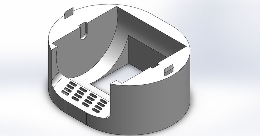
4

2.1 The Main Body of Litter Box

As the loading-bearing part, the middle part provides a platform for the cat when they
jump in and out. It also supports the inner container when the cat occupying or the
owner rotates for cleaning. According to research requirement, the middle part does
not need a complex structure but a shell with thickness. On the other side, digging
some holes in the platform to filter the litter sticks for cats' feet after they buried their
waste as shown in figure 2 below.

Figure 2: The 3D modeling of the middle part

2.2 Inner Rotating Container

The inner container is the core part of our design, it laid the foundation of our design
principle and improvement. Returning to the objectives posed in the middle of the
introduction, the solution of reducing the cost of litter is changing the automatic to full
manpower. Meanwhile, the difference between design and the basic litter box is this
study still need to consider the importance of saving manpower and simplify the
5

cleaning process.

The modeling built a folded plate in the middle can ensure the solid waste rotates into
the center of the waste box instead of the outside of the waste box. When the inner
containers turning to a certain angle, the cylindrical bar run to the garbage drawer, and
the rest clean litter is kept in a saving cell inside the inner container. Then the clean
litter back to the container after turning the inner container to the original angle as the
figure 3 and figure 4 shows.

Figure 3: The 3D modeling of the inner container
6

 Saving cell

 Figure 4: The section view of the inner container

 2.3 The Top Shell Introduction

 The shell and the main body connected with two buckles that make it easy to take the
 shell off and take the inner container out. The inner container needs to clean
 occasionally to ensure the living environment of cats, the detachable shell head shows
 in figure 5.

Figure 5: The 3d modeling of top shell Figure 6: The 3d modeling of top shell with a fixed piece
7

Illustration 6 presents the 3d modeling of the top shell with a fixed piece that used
stable the inner container without rotating. The fixed piece needs to be fixed on the
top shell and inserted into the internal groove of the inner container at the same time.
The existence of the top shell is mainly to fix the inner container and make our design
look more linear.

2.4 The Bottom Base Introduction

The bottle base contains a bottle shell and inside drawer with a small container for
collecting waste. It provides small storage space for placing activated carbon or plastic
bags in the spare space of the drawer as the illustration 7 shows below.

Figure 5: The 3d modeling of the bottom base with drawer assembly
8

Figure 6: The 3d modeling of opened drawer

This design did not add a complicated sliding device on the drawers because that used
in one common way as the garbage storage. It is a garbage bin for cats' waste when
the owners are cleaning and the bin for collecting the falling litter from above. Based
on research requirement, the drawer can be easily pulled in and out if the selected
material has low surface roughness.

2.5 Anti-Slip Bar Design and Selection
The balance of our bottom base increased to ensure it does not tilt even under the
impact force from cats. The bottom base is designed with an oval cutting with a groove
to glue the anti-skid bar. The cut surface of the anti-skid bar is round and the radius is
the same as the groove illustrates in figure 9.
9

 Rubber bar

Figure 7: The 3d modeling of bottom base with rubber bar

The friction force increased by increasing the static frictional coefficient about the
same normal force. From the material friction coefficients, we can find that rubber has
great static friction coefficients in non-metallic materials in table 1.

Table 1: Coefficients of friction (Tammertekniikka, September 2013)

 Materials Static µs Kinetic µk

 Wood – wood (dry) 0,7 0,4

 (lubricated) 0,11 0,075

 Steel – steel (lubricated) 0,12 0,1

 Friction bearing (lubricated) 0,14 0,02 … 0,08

 Leather – Metal (dry) 0,6 0,5
10

 (lubricated) 0,15 0,12

 Rubber – Asphalt (dry) 0,9 0,8

 (lubricated) 0,4 0,2

2.6 Operation Diagram and Exploded View

The design has few parts and the cleaning steps are simple as the above paragraph
described. Here are a few step diagrams to help understand.

Figure 9: The overall section view with fixed piece Figure 8: The overall section view without fixed piece
11

Figure 10: The section view on cleaning process

The illustrations describe the cleaning process as firstly take off the fixed piece on the
top shell, then rotating the inner container by moving the outwards cylindrical bars.
After cleaning the fixed piece have to put in the original place to stable the inner
container. The exploded view like below figure 13 highlights the assembly instruction
and the list of components.
12

 Fixed piece

 Top shell

 Inner container

 Main body

 Garbage bin

 Drawer

 Bottom base

 Rubber bar

Figure 11: The exploded view of the initial design

2.7 Material Selection of Main Parts

This study has to select materials depends on different requirements, here are three
material selection demands for our major parts of design:

 § The cat litter box is an indoor product without consideration of UV exposure and
 weathering.

 § The litter box needs to be corrosion resistant to resist the corrosion caused by
 cat feces and urine.

 § The cat litter box is not a consumables product, high resistance of physical
13

 impacts can let cat owners use it for a long time without break

As a result of material demands, this research selected Acrylonitrile Butadiene Styrene
(aka ABS) as the main material of our design components. It has high toughness and
strength properties to satisfy the demand of physical impact and highly resistant to
chemical corrosion. Because of this point, our design did not choose Polypropylene
(aka PP) but ABS, Polypropylene does not have good resistance to chemical corrosion.
Base on its low melting point, ABS is easily enabled for injection molding to create a
desired design effect. (AdrecoPlastics, 2018)

Table 2: Young's Modulus for non-metal materials (Toolbox, 2003)

 Material Tensile Modulus (Young’s Modulus, Ultimate Tensile
 Modulus of Elasticity) Strength

 (Gpa) (Mpa)

 ABS plastic 1,4 – 3,1 40

 Acrylic 3.2 70

 Nylon-6 2-4 45 – 90

 Nylon-66 60 - 80

 Polypropylene,PP 1,5 - 2 28 - 36

 Polyethylene HDPE 0,8 15
 (high density)

3 The Improvement of Separate Parts

There is another chapter for showing the improvements between the original design
and the ultimate one. The main parts are dominated in our design idea and the way
that can lower the cost is to simplify the manufacturing process by reducing
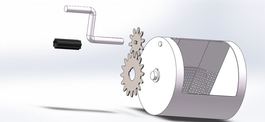
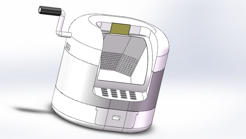
14

replaceable components.

The previous inner container did not do any force-saving operation, and the container
plus the placed cat litter requires a pushing force of several kilograms. The improved
design added a gear device on the side of the inner container to save manpower when
rotating it. The illustration displays that a highlight of the improved design is the
addition of a handle to rotate the inner container in figure 12.

Figure 12: The 3d modeling of improved design

3.1 The Spur Gear System

The research requires a cleaning system that can rotate and save manpower together,
after studying the gear system became the first candidate. As the result of design
demands, selecting a power transmitting system called Spur Gears Device to increase
our rotating force, the force calculates process and formulas shown in the backward
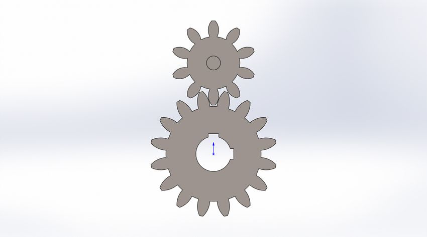
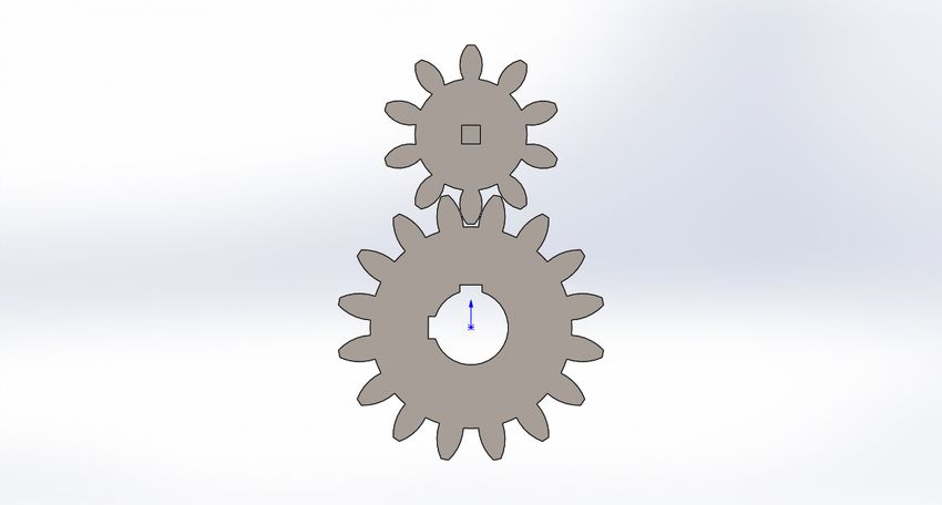
15

section. The principle of manpower cleaning utilizes the handle to rotate the smaller
gear and driving rotation of the inner container by the bigger gear at the same time.
(Woodford, 2020)

On the other hand, the gear system assembly method shown in the figure 13 as the
exploded view. The rubber plug glues it on the handle and there is a cube groove at
the end of the handle to match the cube convex groove in front of the smaller gear.

Figure 13: The 3d modeling of inner container with gear system

From the exploded view, the handle, small gear, and the inner container are all spliced
like Lego. Turning the small gear by the handle alone does not drive the inner container
because the three of them are not fixed together. Only when the pitches of the small
gear and the large gear are overlapped, turning the handle can turn the inner container
as well.

The inner container rotated by turning the small gear to drive the large gear, in that
case, the big gear has to be fixed on the inner container. The big gear has two cutting
keyways to match the inner container and the smaller one has one cylindrical groove
in the back to support it hangs on the inner container as illustration 14 below.
16

 Small gear

 Big gear

Figure 16: The front and back view of gear system

3.2 The Material Selection of The Spur Gear

The material of the gear system used Nylon in our research, the key benefits of nylon
are low self-weight, and the ability to absorb shock and vibration. The elastic modulus
and tensile strength of Nylon 6/10 is much higher than Nylon 101 according to the
information provided in Solidworks as figure 16 and figure 17 shows below. These two
mechanical properties can help the gear system resist tension with the high tensile
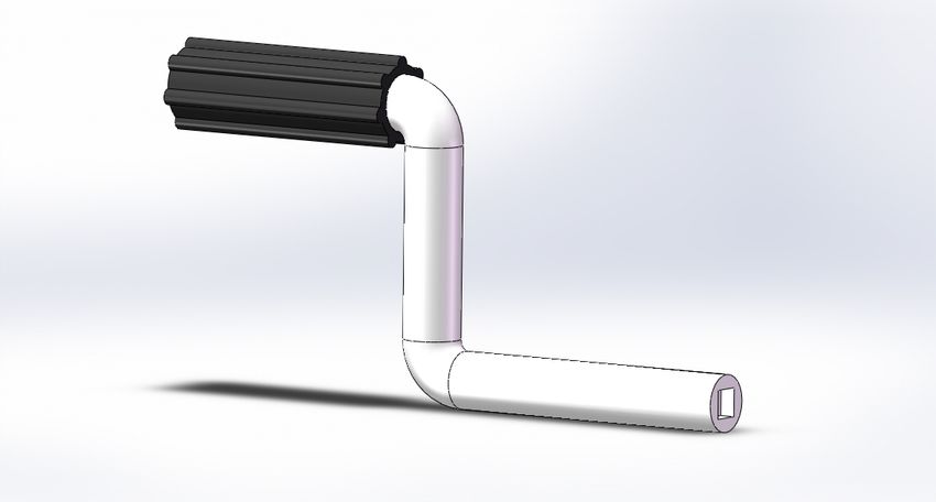
17

strength as it working. (Dengel, 2017)

Figure 14: The mechanical property of Nylon 6/10 in Solidworks

Figure 15: The mechanical property of Nylon 101 in Solidworks

3.3 The Handle Introduction

Most of the design parts use plastic material but the small components such as handle
and sleeve are metal and rubber separately. Handle Sleeve is designed with the
convex and concave rubber surface to increase surface roughness when rotating
handle and the manpower system is learned from the lever principle of the bicycle
pedal.(ToolBox, 2008)
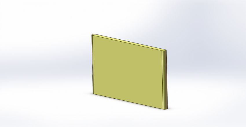
18

Figure 16: The 3d view of handle and rubber sleeve

3.4 The Fixed Piece

The automatic litter box has an automatic calibration function after self-cleaning, for
that purpose, this design adds a fixed piece to stabilize the inner container when the
cat using it. Figure 12 indicates the purpose of the fixed piece, it perfectly matched the
gap between the top shell, and the inner container and the fixed piece through
extremely low tolerance to achieve a fixed effect.

Figure 17: The 3d modeling of a fixed piece
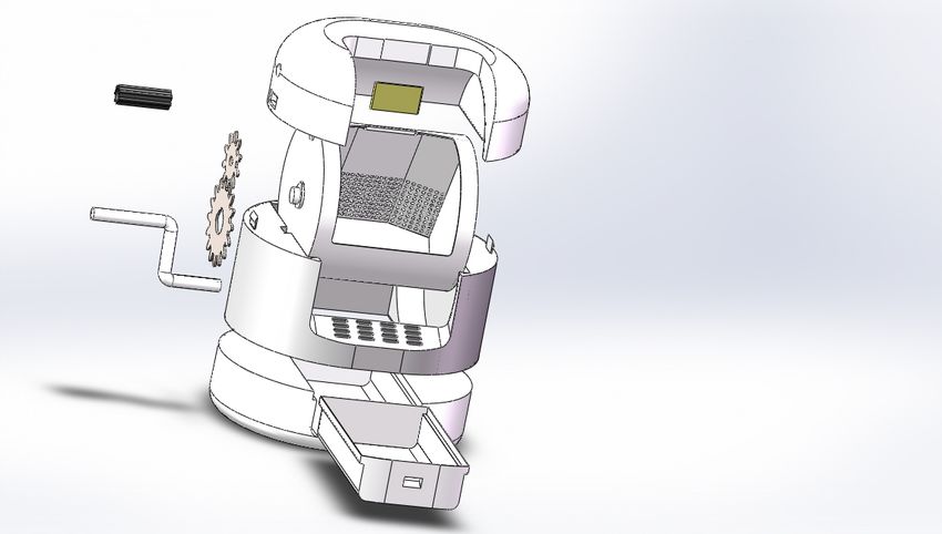
19

 3.5 The Exploded View of Improved Design

 In general, the improved design focuses on saving the force of rotating the inner
 container so that other parts are unchanged except for the inner container, and a hole
 is only added to the top to allow the handle to pass through as illustration 19 shows.

 Top shell
Rubber
 Fixed piece
sleeve

Gear
 Inner container
system

 Main body
Handle

 Bottom base

 Drawer

 Figure 18: The exploded view of the improved design

 The previous paragraph may make the installed process of the gears system
 unimaginable, but with the section view 20 below it became visible. First, the red is the
 small gear, the green is the large gear, and the yellow is the cylindrical support on the
 side of the inner container. The width of the gap on the top shell is smaller than the
 combined width of the large and small gears. Even if there is no cylindrical support on
 the side, the small gear can stand stably on the large gear.
20

 Gap

 Cylindrical support

 Handle

Figure 19: The section view of the gear system assembly

4. The 2D Drawing and Force Calculation

The dimensions of the litter box are also one of the decisive topics in our research.
According to research, domestic cats have a certain preference for the size of the litter
box. The second point is that a litter box that is too small will make it difficult for cats
to move, and if it is too large, it will take up too much space. The results of this study
show that a larger litter box (86 x 39 cm) will be more attractive for cats than a regular
one (56 x 38 cm). Therefore, this design refers to the size of a larger litter box and
decided an external 62 x 50 cm design. (Guy, N. C., Hopson, M., Vanderstichel, R,
2014)
21

4.1 Inner Container Volume Calculation

The more precise calculation must contain the cat litter in the inner container, for that
purpose the result of maximum cat litter capacity is essential in our research. Although
there is a variety of cat litter with different materials and sizes, our study selects one
to calculate the approximate weight of cat litter.

Through the research, the density of cat litter cannot be referred to directly with precise
official data. Base on this situation, we use the product standard from the Draynecs
BVBA to measure the about weight that the inner container can be accommodated.
According to the information provided on Draynecs website, the bulk density of litter is
about 850 gr/ltr +- 6%. (BVBA)

Figure 20: The 2d drawing of the inner container 2

As the figure 21 of the 2d drawing of the inner container 2 shown, the volume can be
22

calculated as the Area multiply Length. The area of a segment of a circle can be
expressed as:

 ! × (1)
 = ( − )
 2 180°

Radius=182.50 mm ;

Angle q=114.76°

 182.5! × 114.76
 = 6 − sin(114.76)= = 18233 !
 2 180°

Length= 370 mm

 = × ℎ (2)

 = 18233 × 370

 = 6746211.1 !

Then converting cubic millimeter to liter is about 6.75 liter.

According to calculation, the volume of the inner container shows in the last equation
result and the next step is calculating the mass by the Density Equation as:

 (3)
 =

Mass = 850 gr/ltr x 6.75ltr = 5737.5 gram ≈ 5.74 kg

As a result of the above calculation shows, the inner container can hold 5.74 kg cat
litter at least.

4.2 The Calculation of Gear System
23

Figure 21: The 2d drawing of gear system

The dimensions we need for calculation shown in section view figure 22. The effort
force of the gear system expressed as below, all the gravity in our study g=9.81 m/s2 .

And where:

 × ( 1 × 2 × … " ) (4)
 =
 1 × 2 × … "

W = load force (N) = Sum of cat litter (inner container and maximum litter);

r = gear wheel inside diameter (m);

R = gear wheel outside diameter (m);

As the result, the force required to turn the inner container with maximum litter inside
after using the gear system is:

 (5.74 + 3.0) × 9.8 × (0.03 × 0.024)
 1 = = 16.92
 0.045 × 0.081
24

4.3 The Calculation of Lever Device

The effort force of the handle expressed as lever equal below (ToolBox, 2008)

 # × # = $ × $ (5)

Where:

Fe = effort force (N) ; Fl = load force (N) ;

dl = distance from load force to fulcrum (m) ;

de = distance from effort force to fulcrum (m) ;

The load force through the gear system is 16.92 N as the calculation above

 # = 16.92 × 0.12 ÷ 0.18 = 11.28

As the result, the force required to rotate the inner container (with the maximum litter inside) after
the gear system and lever device is

 11.28 ÷ 9.81 m/ ! ≈ 1.15

5. 2D Drawing and the Basic dimension of Components

This chapter contains the 2d drawing and basic dimensions of different component
parts to simulate the manufacturing process in our study. The 2d drawing has more
details rather than 3d drawing, such as weight, scale, material for our components.

5.1 2D Drawing of Top Shell

The previous illustrations indicate that there is no change in the main body and the
bottom base of the design in the first and second editions. The top shell added two
cutting holes on the side to enter the handle and a place for small gear separately,
and the inner container is the most significant change during our design process. The
2d drawings below indicate the differences mechanically and the components in the
25

same dimension are not repeated show in our study.

Figure 22: The 2d drawing of top shell

The top shell is a symmetrical object in the initial design, after the improvement, two
holes have been added to become an asymmetrical object, but the other dimensions
are the same. Since the top shell did not bear too much force, this study did not run
the force simulation for it.

5.2 2D Drawing and Simulation Report of the Main Body
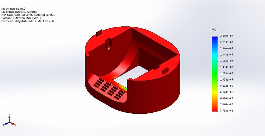
26

Figure 23: The 2d drawing of main body

The main body has to support the top shell and the inner container with the full of the
cat litter, it is necessary to do force simulation. The Solidworks report indicates the
fixed area is under the main body and the load force is above the main body within its
own gravity. Our study adds 200N force on the main body and the result of the factor
of safety (aka FOS) verified that our component can load far beyond 200N because
the minimum FOS is about 37 as the figure 26 reports.
27

 Loads and Fixtures
 Fixture name Fixture Image Fixture Details
 Entities: 1 face(s)
 Type: Fixed Geometry
 Fixed-1

 Resultant Forces
 Components X Y Z Resultant
 Reaction force(N) -0.015071 240.794 0.00495791 240.794
 Reaction Moment(N.m) 0 0 0 0

 Load name Load Image Load Details
 Entities: 1 face(s)
 Type: Apply normal force
 Value: 200 N
 Force-1

 Reference: Top Plane
 Values: 0 0 -9.81
 Units: m/s^2
 Gravity-1

Figure 24: Loads and Fixtures report of the main body

 Name Type Min Max
 Factor of Safety1 Max von Mises Stress 3.712e+01 2.458e+07
 Node: 37836 Node: 20104

 Analyzed with SOLIDWORKS Simulation Simulation of body2 5

 body2-Static 1-Factor of Safety-Factor of Safety1

Figure 25: Factor of safety of the main body
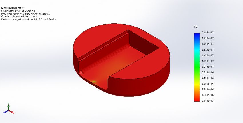
28

5.3 2D Drawing and Simulation Report of the Bottom Base

As the bottom of the base, it carries all the components and litter and the cats, its FOS
must be high enough to avoid fracture. In order to avoid deformation caused by high
temperature, it is prefer to use glue to connect the bottom and body parts.

Figure 26: The 2d drawing of the bottom base
29

 Name Type Min Max
 Factor of Safety1 Max von Mises Stress 2.745e+03 2.157e+07
 Node: 48637 Node: 21294

 bottle2-Static 1-Factor of Safety-Factor of Safety1

Figure 27: The factor of safety report of the bottom base

From the result of FOS of the bottom base in figure 30, our design component has an
Conclusion
excellent quality to load the force far more than 200N.

5.4 2D Drawing of inner container 1

The improved inner container has been exhibited above, and here is the initial 2d
drawing for reference and comparison as figure 31.

 Analyzed with SOLIDWORKS Simulation Simulation of bottle2 10
30

Figure 28: The 2d drawing of inner container 1

5.5 2D Drawing of rest components

The rest parts are displayed in one table, they have different scales as shown in the
illustration 30 including the list of parts.
31

Figure 29: The 2d drawing of the rest components

6. Summary

This research did not include more precision instruments but focused on the design
plan and design concept. Improve the design size through Solidworks, and then use
the simulator to ensure the safety of the design.

The core part is the inner container, which needs to balance the design size and force
saving device. That caused the first edition of the inner container needs to be improved
in some way. As the result of that, the combination of gears system and levers device
perfectly reduces the force that needs to be applied.

This research not only shows a design process but also a learning process for
researchers. Another important research goal is to explain to people who don't
understand mechanical manufacturing that this major is more interesting and closer to
32

life than they thought. The knowledge learned in machine manufacturing is not only
used in laboratories or factories but is often applied in real life.

This research has undergone a series of improvements from the beginning of
determining the direction to finding the target. Constantly exploring new directions from
improvements is the purpose of our learning.
33

Reference
CatsProtection, Toileting. [Online]
Available at: https://www.cats.org.uk/help-and-advice/home-and-environment/toileting
ToolBox Engineering, 2004. Friction and Friction Coefficients. [Online].
AdrecoPlastics, 2018. ABS plastic properties. [Online]
Available at: https://www.adrecoplastics.co.uk/abs-plastic-properties-and-application/
Tammertekniikka, September 2013. Technical formulas.
Toolbox Engineering., 2003. Young's Modulus - Tensile and Yield Strength for common Materials.
[Online]
Available at: https://www.engineeringtoolbox.com/young-modulus-d_417.html
Woodford Chris., 2020. Gears. [Online]
Available at: https://www.explainthatstuff.com/gears.html
Dengel, Brain., 2017. Plastic Gears Are the Future. [Online]
Available at: https://www.machinedesign.com/materials/article/21836156/plastic-gears-are-the-
future
Guy, N. C., Hopson, M., Vanderstichel, R, 2014. Litterbox size preference in domestic cats (Felis catus).
BVBA, Draynece., n.d. Bentonite Standard. [Online]
Available at: http://www.draynecs-catlitter.com/product?id=23
ToolBox Engineering., 2008. Levers. [Online]
Available at: https://www.engineeringtoolbox.com/levers-d_1304.html
Niinimäki E., 2020. Number of pet cats in Finland 2010-2019. [Online].
CatProtect. Toileting. [Online]
Available at: https://www.cats.org.uk/help-and-advice/home-and-environment/toileting
LitterRobot. Solving The Litter Box Problem. [Online]
Available at: https://www.litter-robot.com/eu/how-it-works.html
LitterRobot. When You Ask An Engineer To Scoop The Litter Box…. [Online]
Available at: https://www.litter-robot.com/eu/about-us.html
Cadtek, 2020. 5 Reasons To Use SOLIDWORKS. [Online]
Available at: https://www.cadtek.com/5-reasons-use-
solidworks/#:~:text=SOLIDWORKS%20is%20a%20very%20productive,suit%20all%20types%20of%20desig
n.
LitterRobot3,. Litter-Robot 3 Connect. [Online]
Available at: https://www.litter-robot.com/eu/litter-robot-iii-open-air-with-connect.html
34

List of figures

Figure 1: The overall of 3D representation of the initial design..................................................................... 3
Figure 2: The 3D modeling of the middle part...................................................................................................... 4
Figure 3: The 3D modeling of the inner container .............................................................................................. 5
Figure 4: The section view of the inner container ............................................................................................... 6
Figure 7: The 3d modeling of the bottom base with drawer assembly ....................................................... 7
Figure 8: The 3d modeling of opened drawer ...................................................................................................... 8
Figure 9: The 3d modeling of bottom base with rubber bar ............................................................................ 9
Figure 11: The overall section view without fixed piece ................................................................................. 10
Figure 10: The overall section view with fixed piece ....................................................................................... 10
Figure 12: The section view on cleaning process............................................................................................. 11
Figure 13: The exploded view of the initial design ........................................................................................... 12
Figure 14: The 3d modeling of improved design............................................................................................... 14
Figure 15: The 3d modeling of inner container with gear system .............................................................. 15
Figure 17: The mechanical property of Nylon 6/10 in Solidworks .............................................................. 17
Figure 18: The mechanical property of Nylon 101 in Solidworks ............................................................... 17
Figure 19: The 3d view of handle and rubber sleeve ...................................................................................... 18
Figure 20: The 3d modeling of a fixed piece ...................................................................................................... 18
Figure 21: The exploded view of the improved design ................................................................................... 19
Figure 22: The section view of the gear system assembly ........................................................................... 20
Figure 23: The 2d drawing of the inner container 2 ......................................................................................... 21
Figure 24: The 2d drawing of gear system.......................................................................................................... 23
Figure 25: The 2d drawing of top shell.................................................................................................................. 25
Figure 26: The 2d drawing of main body ............................................................................................................. 26
Figure 27: Loads and Fixtures report of the main body ................................................................................. 27
Figure 28: Factor of safety of the main body ...................................................................................................... 27
Figure 29: The 2d drawing of the bottom base .................................................................................................. 28
Figure 30: The factor of safety report of the bottom base ............................................................................. 29
Figure 31: The 2d drawing of inner container 1................................................................................................. 30
Figure 32: The 2d drawing of the rest components ......................................................................................... 31

List of tables

Table 1: Coefficients of friction (Tammertekniikka, September 2013) .................................................... 9
Table 2: Young's Modulus for non-metal materials (Toolbox, 2003) ..................................................... 13

List of equations

equation(1) ........................................................................................................................................... 22
equation(2) ........................................................................................................................................... 22
equaiton(3) ........................................................................................................................................... 22
equation(4) ........................................................................................................................................... 23
You can also read