CBI fMRI Equipment and Eprime Guide - College of Medicine ...
←
→
Page content transcription
If your browser does not render page correctly, please read the page content below
CBI fMRI Equipment and Eprime Guide
Getting Started
1. Meet with about your experimental needs – the most important questions are:
           A. What tasks do you want to run?
           B. What level of timing precision does your experiment require?
           C. What software environment do you prefer?
           D. What peripheral equipment do you require?
           E. Do you have experience with experiment development in eprime or whatever software
               environment you want to use? Jayce can provide technical assistance if needed.
   2. Jayce will set you up with a login/password for the presentation computers
   3. If you want to do general eprime development, you can use a computer located in the back of the
       scanner control room with an eprime 2 and eprime 3 license. Please schedule the eprime computer on
       Calpendo, since others may want to use it. BACKUP ANYTHING MADE ON THIS COMPUTER! Your
       eprime development files are your own responsibility.
   4. If you have never used eprime before, there are many resources available:
           A. In eprime, there is a “Getting Started Guide” accessible through the help menu.
           B. Youtube has over 100 Eprime tutorials available for free. The following link will take you to the
               various playlists (ie Basic Topics, Experiment Designs etc).
               https://www.youtube.com/user/PSTNET/playlists
           C. Psychology Software Tools (PST) now offers Basic E-Prime webinars for FREE! 14-day access to
               10 advanced webinars can also be purchased. http://www.pstnet.com/eprimetraining.cfm
           D. PST also has a very comprehensive support page, with about 50 example programs
               demonstrating how to do just about every kind of common task in eprime. You will need to
               make an account with them to access everything. http://www.pstnet.com/support/kb.asp
   5. Once you have your experiment working, we will need to schedule scanner time to make sure it works
       with all ancillary systems (button boxes, etc). There is information below that outlines most of the
       changes required.
   6. TEST, TEST, TEST! Validate button responses in your data files, check triggers, timing, audio volume
       loud enough, audio recording working well, display looks correct, etc.
   7. Once you are satisfied with your task, we will need to make a matching fuctional ep2d MRI sequence
       on the scanner.
           A. You do not need to account for dummy scans if you use a trigger – the MRI runs a few scans at
               the start of the sequence, but the data is discarded. It then sends a trigger pulse on the start of
               the 1st real scan, which will start your experiment.
           B. The most commonly used TR is 2200, because our optimized sequence that minimizes artifacts
               uses this. Other TRs are possible, but you MUST test your sequences very, very carefully on
               PEOPLE, not just phantoms, for artifacts.
           C. Once you know your desired TR (ex: 2200ms) and how long your task takes (ex: 600s), just
               divide the task time by the TR (with appropriate units) and round up (ex: 273). This number
               corresponds to the # of measurements you want in your sequence.
           D. If you want to know more about fMRI on a Tim Trio, you can visit these excellent resources
               from UC Berkley and Harvard (just ignore the special sequence info):
               http://bic.berkeley.edu/sites/default/files/3T_user_training_FAQ_08Mar2012.doc
               http://cbs.fas.harvard.edu/science/core-facilities/neuroimaging/information-
               investigators/MRphysicsfaq

Last Updated, 12/19/2018, Scott Henderson
                                                        1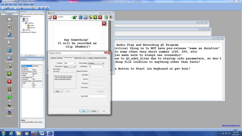
8. TEST, TEST, TEST (again)! Make sure you are fully satisfied with image data (artifacts, etc), response
      data, physio data, timing, etc.

Presentation Computers Data Policies

All users have administrator privileges (required to build/run EPrime software). Be aware that any changes
made (e.g. changing port settings or device drivers) can impact other users! DO NOT MAKE SYSTEM
CHANGES OR INSTALL SOFTWARE WITHOUT CBI PERMISSION!

USERS ARE RESPONSIBLE FOR BACKING UP THEIR OWN PARADIGMS AND EPRIME DATA!

CBI makes a nightly backup of eprime data files to the research repository. We also periodically make a clone
of the entire computer the eprime programs are run from, but this is primarily to preserve system
configuration, not individual data files. It is your responsibility to copy/move your eprime data files to make
sure you have them in the case of a hardware malfunction. If a hard drive crashes and your data files are not
on the backup, then there is no chance of recovery, thus, BACKUP OFTEN!

All experiment and data files must be stored on the D: drives of the Presentation computers, NOT on the
desktop or C: drive.

Flash drives are physically blocked on the MRI Scanner computer and the old Presentation-1 computer. To
transfer files from these computers, see Jayce or Tom for network drive instructions. You can use flash drives
on the other computers.

30 Bee St Presentation Equipment:

   1. Computers:
         A. Presentation-0:
                 i. Primary fMRI Presentation Computer
                ii. ASUS Xonar D2X Audio Card for Eckert Lab installed
               iii. 2 parallel port PCIe card install – one is for trigger input, TMS firing, and firing of
                    secondary stimulus devices, while the second one is for EEG event marking. Hardware
                    addresses are:
               iv. COM1 port should be used for PST Button Box – connected via Prolific USB-Serial
                    adapter
                v. COM3 port should be used for MRA button box – also USB-serial adapter
               vi. Connected to Black Box Toolkit USB TTL Module – used for Biopac system event marking
                    – address should be COM6.
              vii. Windows 7 Pro 64 bit
                        1. Runs Eprime 2.0.10.242, Eprime 3.0, MATLAB 2012, Presentation 18 (USB license
                            key is kept by Lisa McTeague).
                        2. Hooked up to Projector, Button Boxes, Audio Systems, Eyetracker, Trigger Box,
                            TMS firing, EEG and Biopac event marking.
              viii. Ubuntu Linux 14.04.2, 64-bit installed in 2nd partition
                        1. Runs Python 2.70, Anaconda, Pylink (for eyetracker), Pygame
Last Updated, 12/19/2018, Scott Henderson
                                                       2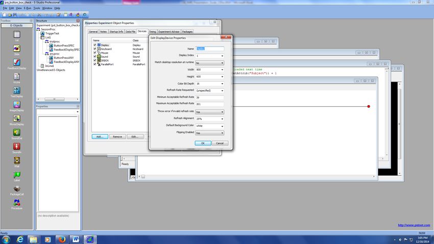
B. Presentation-2:
                  i. Secondary Presentation computer for simultaneous use with Pres-0 or Pres-1 (usually
                     for audio experiments or Turbo Brain Voyager)
                 ii. ASUS Xonar D2X Audio Card for Eckert Lab installed
                iii. Windows 7 Pro 64-bit
                iv. Runs Eprime 2.0.10.242, Turbo Brain Voyager 3.2 (realtime fMRI software, no longer in
                     active use), BrainProducts EEG Software
                 v. Hooked up to trigger box, Eckert Sensimetrics earbuds, and audio recording.
                vi. NOT hooked up to projector, eyetracker, button boxes, tms, etc
               vii. Also serves as spec data storage for Jim Prisciandaro

         C. Realtime Mac Laptop:
                  i. Mac OSX 7.5 (Lion)
                 ii. Runs MATLAB, Psychtoolbox, and Xcode experiments
                iii. Formerly used with LabVIEW and Turbo Brain Voyager, but TBV is moved to Pres-2 for
                     stability and LabVIEW is no longer used.
                iv. NOT connected to trigger or button boxes by default – MUST BE MANUALLY connected
                     and disconnected through USB.
         D. Eyetracker Host PC:
                  i. Used ONLY for Eyetracking (host PC)
                 ii. Dual Boot – Eyelink RTOS (for data acquisition) and Windows 7 32 bit (for getting data
                     files)
                iii. ONLY connected to Eyetracker camera and Presentation-0 PC. No network access, all
                     data transfers must happen by USB.
         E. Biopac Physio Acquisition Laptop:
                  i. Dell
                 ii. Hooked up to Ethernet port, crossover cable, USB-ethernet adapter, and power, and
                     license key – no other connections. Network is OK.
               iii. Just used for biopac data acquisition – MP150 system is in rear equipment room,
                     hooked up to Ethernet crossover cable, also trigger from scanner through extender, and
                     parallel port signal through rack from BBTK.
         F. Laptop Support:
                  i. While we strongly encourage using one of our computers for your experiments (since
                     we support Windows, Mac, and Linux), we also have laptop hookups for the scanner
                     trigger, button boxes, projector, and audio systems if you prefer to run off your own
                     hardware.
2. Supported Software:
         A. Eprime 3
         B. Eprime 2.0.10.242
         C. Eprime 1 and 2.0.8.79 (OLD studies only)
         D. Psychtoolbox 3
         E. MATLAB R2012a and 2015a
         F. Turbo Brain Voyager 3.2 (no longer in active use)
         G. SR Research Experiment Builder / Pylink – for eyetracker
         H. Anaconda Python and Pygame
         I. Presentation 18 (contact Lisa McTeague for use of license key)
         J. Other software environments can be installed, contact Jayce if interested.
Last Updated, 12/19/2018, Scott Henderson
                                                     3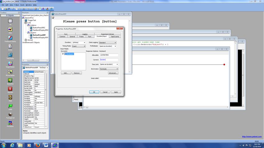
3. Supported Coils:
          A. 32-channel Head Coil (Siemens) – recommended for most new studies due to improved SNR. It
              is a tighter fit for many subjects though.
          B. 20-channel Head/Neck Coil (Siemens)
          C. 12-channel TMS Head Coil – for use only when performing TMS in scanner
          D. Spine 32 (Siemens)
          E. Flex Large 4 and Flex Small 4 Coils (Siemens)
          F. Body 18 Coil (Siemens)
          G. Hand/wrist 16 (Siemens)
          H. QED TxRx 15 Channel Knee Coil
          I. For more information on the use of each of these, contact CBI techs (CBItech@musc.edu).
4. Visual Presentation:
          A. New MRI-compatible Hyperion Projector from Psychology Software Tools. There is also custom
              mirror projection.
          B. Uses DVI input
          C. Requires a minimum resolution of 800 x 600 for eprime display
          D. Can support up to 1920 x 1080 images
          E. Controlled by ConnectPro KVM switch located in rack above console. Use remote or buttons
              on front of switch to change computer input to Pres-0, Pres-1, Mac, or Laptop computers.
   5. Audio Presentation:
          A. 3 Audio Systems:
                    i. Avotec Headphones Earbuds and Microphone. This system is used with most studies
                       except those focused on Auditory.
                   ii. Standard Siemens Speaker - (Can be used to speak to and hear subjects with all head
                       coils on but subjects have a more difficult time hearing with this system than the
                       Avotec. This is usually only used when other systems are not Works fine for voice and
                       not very sensitive audio tasks.
                  iii. Sensimetrics S14 Earbuds – Owned and used by Eckert Lab. Small and fit in any
                       headcoil, require special audio amplifier and transformer, but offer exceptional sound
                       quality.
          B. Audio Control Box – Audio system selection is controlled by a box at the front of the scanner
              console. Hit the buttons to select the computer you are playing audio from (Pres-0, Pres-1,
              Mac, or Laptop) and move the audio jacks to select your audio system.
   6. Audio Recording:
          A. Resonance Technology Serene Sound Headphones – they have a microphone attached (make
              sure it is very close to the subject’s mouth). Can be used with either Presentation-0 or
              Presentation-2 computer for recording in Eprime or Audacity. Make sure Recording Volume is
              at 60 minimum.
   7. Handpad Response:
          A. 3 Button Box Systems:
                    i. CURDES fORP 932 interface and Pyka handpad – Owned and supported by CBI. Primary
                       interface is a 5 button grip style handpad to be used in either the left or right hand. This
                       is what most groups currently use. Other labs have peripherals that work with the 932
                       interface, including a 2 button box, a joystick and grip force dynamometers.
                   ii. MRA fMRI Button Box – Owned by Jane Joseph’s lab, includes individual, single finger
                       button boxes. Great for use with kids or individuals with small hands that PST box does
                       not work with.
Last Updated, 12/19/2018, Scott Henderson
                                                        4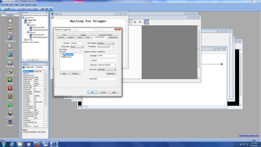
iii. Psychology Software Tools (PST) / Brainlogics Fiberoptic BRU – Owned by CBI, offers
                       left and right handpads for making button responses. This is used to be the most used
                       handpads but the company no longer supports these so we are encouraging all groups
                       to move to the PYKA handpad (#1 above) as we will not be able to fix it when it breaks.
                       Realize that it has 2 possible outputs – Serial and USB. 99% of groups use the serial
                       output (COM1) due to better latency (~3ms). Laptop and Mac users must use the USB
                       (HID) output, which has worse latency (~50ms) but works. Contact Jayce for details.
                  iv.
   8. Trigger Boxes:
           A. 3 peripheral devices:
                    i. Trigger Box – the primary trigger box is located on the scanner console desk, and has 5
                       BNC connectors on it. 2 are for eprime specific TTL outputs, 2 are for general TTL
                       outputs, and 1 is for the trigger simulator box. This box is connected to the
                       Presentation-0, 1, and 2 computers via the parallel port.
                   ii. Trigger Simulator – this is located in a box on the racks in the console room – used for
                       testing stimulus program without having to run the scanner to generate triggers.
                  iii. USB Trigger Box – Primarily used for laptops, adapter box based on the UHID Nano dev
                       board that translates TTL pulses from a BNC connection to HID keyboard presses (‘t’)
                       across a USB connection. Works on any computer and operating system. Hooks into
                       trigger box via BNC and plug USB into computer you are presenting from.
   9. Eyetracking:
           A. SR Research Eyelink 1000 – MRI-compatible eyetracking system, works extremely well for
              adults, more difficult for populations with smaller heads, like children. Uses custom front
              surface mirrors that mount onto the 32 or 12 channel headcoils and interfaces with
              Presentation-0 display computer (Windows or Linux).
   10. TMS:
           A. Magstim Super Rapid TMS Stimulator – 15+yr old TMS stimulator, but it still works. Adapted
              to work in the MRI environment via a filter and special coil backing. Firing controlled by Eprime
              from Pres-0 computer.
   11. Olfactometer:
           A. Emerging Tech Trans (ETT) Olfactometer – Owned by Bernadette Cortese, used for olfactory
              stimulus in MRI.
   12. MRI Goggles:
           A. Cambridge Research Systems Medigoggles (2 sets) – These are MRI-compatible goggles with
              push-in lenses so people that normally use glasses can see in the MRI. We have 1 set for adults
              and 1 set for children.
   13. Mock Scanner:
           A. Custom Made – Mock scanner was custom made by local contractor, and matches bore
              dimensions of real scanner. You can use it to test subjects for claustrophobia (or see if they’ll fit
              in the bore), or pre-run tasks to improve performance in the scanner.
   14. Physiological Monitoring:
           A. MRI-compatible physio system used to record heart rate, respiration, 3 lead ECG and EDA
              data. This is the most used physio system on the scanner.
           B. Invivo Research Inc, 3150 MRI Physiological Monitor – MRI-compatible physio monitor, can
              measure 3-lead EKG, SPO2, ETCO2, Blood Pressure. Wireless receiver box (Millenia) is NOT
              MRI-compatible and stays outside the room. Only used for monitoring patients, NOT for
              recording data.
Last Updated, 12/19/2018, Scott Henderson
                                                        5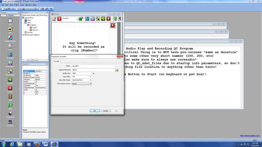
C. Siemens Wireless Physio Monitors – Physio monitors that came with the Siemens MRI console.
              Support 3 lead EKG, pulse, and respiratory effort monitoring (chest strap). By default, data is
              NOT recorded, but can be. See Jayce for details.
   15. Neuroscan 64-channel MRI EEG Synamps RT and Maglink Cap – MRI-compatible EEG system for use
       in scanner. Rarely used – if you want to use it, contact Jayce.

             How to Setup Your Eprime Experiments for use on MRI Presentation Computers
                              (Note that File Paths in Eprime use ‘/’ NOT ‘\’!!)
           (Also, to terminate your experiment while running, hit ctrl-alt-shift, NOT ctrl-alt-del!!)

   1. Setting Display Resolution:
          a. You can set your experiment display resolution in Eprime by double clicking on “Experiment” at
             the root of the tree in the “Structure” window in Estudio. Then double click on “display” and
             change your “width” and “height” to what you want (see below). Leave all other parameters at
             the default settings.

          b. The Screens on the Presentation computers will NOT support display resolutions below 800 x
             600. If you try to run an eprime experiment below that resolution, you will likely get a timing
             error.

Last Updated, 12/19/2018, Scott Henderson
                                                      6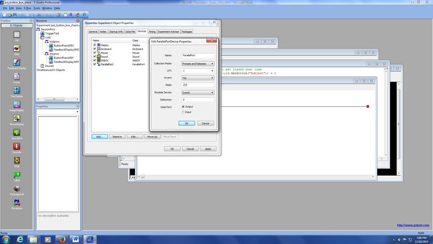
c. The Projector / Screens will support up to 1920 x 1080 resolutions. Make sure that your images
             are scaled appropriately for your display resolution. If you have a bunch of pictures that are
             600 x 400 resolution and you set your eprime display to 1920 x 1080, the pictures will appear
             VERY small (because you are only occupying a small section of the screen). Conversely, if you
             have images that are 800 x 600, and you set your Eprime display resolution to 800 x 600, the
             images will appear to take up the entire screen. So the size of your images matter!

   2. Triggering From the Scanner
          a. Triggers are sent from the MRI scanner at the start of each TR / image acquisition via a fiber
             optic wire to the trigger box. Most people use this to start their experiments (that way they
             don’t have to care about dummy images at the start of scans). This method will be described
             below. Some people will also “lock” their experimental phases to each scanner TR – if you want
             to do this, talk to Jayce.
          b. Every time the trigger box receives a pulse, the RED LED on it will blink.
          c. To enable triggers on Pres-0 and 2 (NOT PRES 1), double click on “Experiment” under the
             “Structure” window in Eprime. Click on the “Devices” tab and “Add…” at the bottom. Select
             “ParallelPort” by double clicking on it, and edit the properties to match the image below
             EXACTLY. Then click OK, and APPLY.

Last Updated, 12/19/2018, Scott Henderson
                                                    7
d. Next you will need to create a slide in Eprime that will only terminate when it receives a trigger
            pulse. You will use this slide to start your experiment.
         e. In the image below, there is a slide called “TriggerTest” at the beginning of my experiment.
            Open up your slide by double clicking on it, then click on the “Properties Page” icon. Go to the
            “Duration / Input” tab and set
                  i. Duration: (infinite)
                 ii. Under “Input Masks” click “Add” and add “ParallelPort” and also “Keyboard.”
                iii. After adding, click on ParallelPort and edit the Response Options on the right side.
                iv. Change “Allowable” to {ANY} and “Time Limit” to (same as duration) and “End Action”
                     to Terminate
                 v. Finally, click on “Keyboard” under Devices and set “Allowable” to {F6}. This allows you
                     to manually trigger by pressing the F6 key on the keyboard for testing purposes.

Last Updated, 12/19/2018, Scott Henderson
                                                     8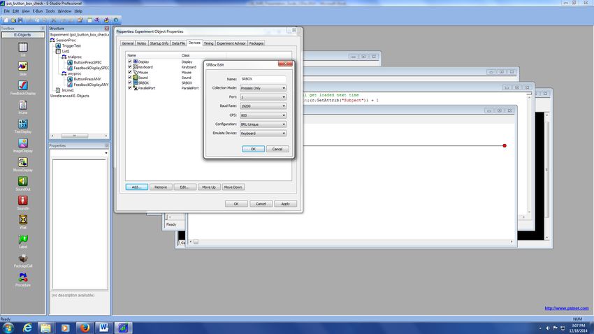
3. Setting Up Button Boxes
          a. Brainlogics / Psychology Software Tools (PST) Button Box
                 i. To set your experiment up to use it, double click on “Experiment” inside the structure
                    window, and click on the “Devices” tab. Add a SRBox, and edit the parameters to match
                    the image below. Most importantly:
                        1. Port must be set 1
                        2. Configuration set to BRU Unique,
                        3. Emulate Device set to keyboard

                 ii. Note that the right hand is mapped as (thumb to pinky) 1,2,3,4,5 and the left hand is
                     mapped as 6,7,8,9,A (and A must be capitalized).

Last Updated, 12/19/2018, Scott Henderson
                                                     9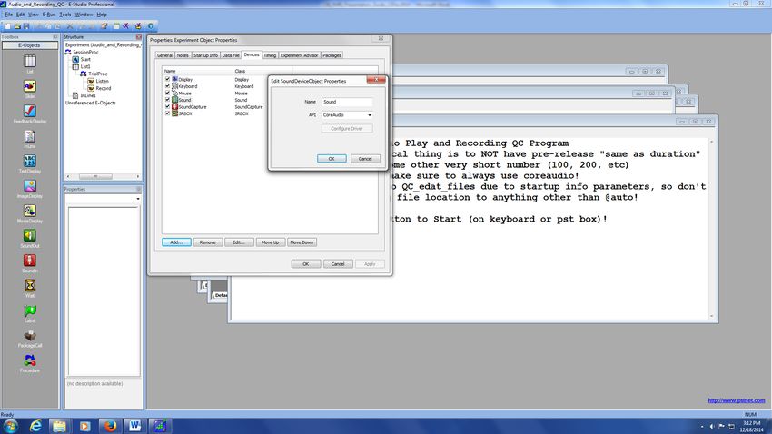
b. MRA Button Box
               i. This button box is owned by Jane Joseph and is more commonly used for children (since
                  individual boxes can detached from each other, making it easy to size to small hands).
                  Setup is the same as for the PST Button Box (see image below), except that:
                      1. Port is set to 3
                      2. Configuration is set to Standard
              ii. Each individual box is mapped as 1,2,3,4,5

         c. CURDES fORP Button Box (Pyka handpad)
                i. Using this device with eprime does not require any special setup – it is recognized as just
                   another keyboard, so as long as you have the default eprime keyboard set up on the
                   devices tab, it will work.
               ii. This box is mapped as (pinky to thumb) 1,2,3,4,5 and triggers are sent as the letter ‘t’

Last Updated, 12/19/2018, Scott Henderson
                                                    10
d. Setting up slide for button response logging (works for PST, MRA, and fORP boxes)
i. After setting up your device properties, go to the slide in your experiment you would
like to log button presses on, then open it up, and click on the “Properties Page” icon in
the top left corner.
ii. Go to the “Duration/Input” tab and click “Add” under “Input Masks.” Add a keyboard
device.
iii. Change the “Allowable” field to the buttons users will be pressing during the
experiment. If this is the PST box, it will be 123456789A, as shown below, all strung
together. If it is the MRA or fORP boxes, it will just be 12345 all strung together.
iv. I DO NOT RECOMMEND PUTTING {ANY} IN THE ALLOWABLE FIELD FOR THE KEYBOARD!
IT IS MUCH BETTER IF YOU JUST PUT THE BUTTONS THE BUTTON BOX CAN PRODUCE /
YOU ARE INTERESTED IN.
v. Make sure to set “Data Logging” to STANDARD! The default is NONE, and if you leave it
on that, it will LOG NOTHING!!
Last Updated, 12/19/2018, Scott Henderson
11vi. You can set your duration to whatever you need, and most people will change the “End
Action” field to “Nothing” rather than “Terminate” but it depends on what you want to
do. Ask Jayce for tips.
4. Setting up Audio Output
a. Audio setup requires proper setting of the audio switch (mentioned above) to the computer
you are using, and the headphone system you are using. Most users just use the Siemens
pneumatic headphones for the 12 or 32 channel headcoil.
b. The most important part of setting up audio in eprime is making sure you choose the correct
API. The recommended choice is “CoreAudio.” You can change this by double clicking on
“Experiment” again and going to the “Devices” tab and double clicking on the “Sound” object
and changing the API. Then hit OK and Apply. This setting will minimize your sound latency.
Last Updated, 12/19/2018, Scott Henderson
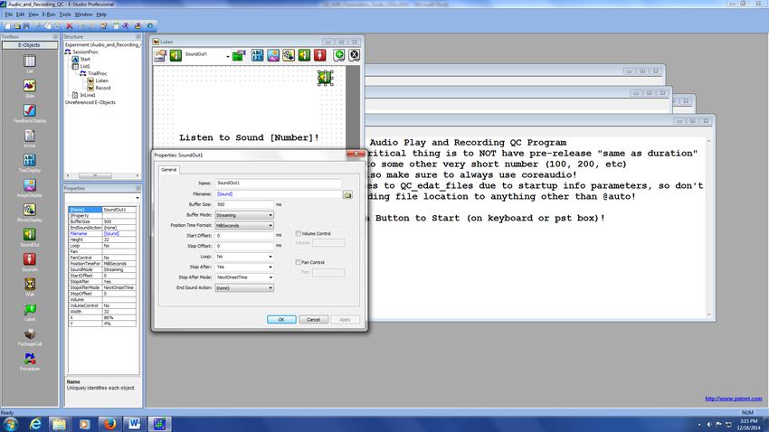
12c. Setting up Audio Output on Slide
i. On a normal slide object, add a “SoundOut” object and open up its property page by
clicking on the green property page button at the top.
ii. Select the file name or set an attribute for what you want played.
Last Updated, 12/19/2018, Scott Henderson
13iii. Next set your mode to streaming – in this mode, you don’t really need to worry much
about your buffer size, but you can set it to 500.
iv. You can leave the other options as default unless you want to use special features.
5. Setting up Audio Recording
a. Audio is recorded through the ASUS Xonar D2X Soundcard. You need to make sure this is
selected as the default recording device in windows. Verify this by going to Control Panel à
Last Updated, 12/19/2018, Scott Henderson
14Sound à Recording Tab à Verify ASUS Xonar is the device with a green checkmark next to it.
The input used is “Line In.”
b. To setup recording in eprime, you need to add a SoundCapture device on your devices tab. The
default settings should be fine.
Last Updated, 12/19/2018, Scott Henderson
15c. To setup audio recording on your slide, you will need to add a “SoundOut” object to the slide
(by dragging), which is a red button with a microphone. Select it, then hit the green properties
button with the pointer finger. Here you can specify where your audio recordings get saved
(@Auto just means they will be saved in the same directory as your eprime file). Buffer size is
the length of your recording. You can leave the rest the same.
Last Updated, 12/19/2018, Scott Henderson
16d. Finally, you will need to make sure that your sound recording buffer size and the duration of
your slide are agreeable. You don’t want to have a buffer size of 2000ms and a slide duration of
1000ms, otherwise you will get an error. Make sure your prerelease is NOT set to “same as
duration” otherwise you will have problems. Just set it to 100ms, it should be fine.
Last Updated, 12/19/2018, Scott Henderson
176. Setting up TMS Firing
a. TMS firing is controlled via Eprime from the presentation computers. Currently Presentation-0
is the computer used to fire the TMS (Presentation-1 was used in the past, but has been phased
out for TMS).
b. A typical TMS-fMRI experiment will have the subject receive TMS at a specific TR interval, and
sometimes at a specific frequency. The fastest frequency used to date is 7Hz stimulation.
Eprime will count the # of TRs that have elapsed in the experiment (via parallel port &hB011),
and when this matches your predefined # of TRs interval, it will send a trigger pulse through
parallel port &hB010 to fire the TMS. Most TMS experiments want to fire the TMS 100 ms prior
to the next TR, so here is a typical example:
i. I want to fire the TMS every 4 TRs, and my sequence has a TR of 2200 ms. In this case,
Eprime would count the 4 TRs, and wait for 2100 ms (100 ms prior to next TR), then fire
the pulse. This is to minimize image artifacts and also ensure correct observation of the
TMS effect in the MRI data.
c. Once Eprime fires through the parallel port, the signal is passed along a BNC cable through the
ceiling to the rear equipment room where the Magstim Rapid Stimulator sits.
d. This signal is fed into a custom “TMS Isolation Box” that prevents back propagation of signal
along the BNC cable. This allows for use of % outputs up to 100%. However, in practice, the
MAXIMUM % output that should be used is 95%. Anything higher than that puts a lot of stress
on the TMS coil. Make sure the isolation box is turned ON (GREEN LED ON)!
e. The isolation box passes the firing pulse to the Magstim TMS stimulator through a BNC port on
the back. The Magstim fires, sending the pulse through a RF filter into the figure 8 coil inside
the MRI room. See a system diagram below:
Last Updated, 12/19/2018, Scott Henderson
18f. For practical purposes, most users only need to modify the timing of the TMS firing. To do this,
obtain a working copy of the TMS firing program from Jayce. There is a part of the experiment
called “TriggerList” – the 2 parameters that you want to change are:
i. “Time_from_TROnset_to_TMS_Trigger_millisec” – much like the name says, this
specifies the delay from the time of the desired TR, to when the pulse is actually fired.
Generally this number is your sequence’s TR – 100ms.
ii. “TR_number” – the desired TR during which you want to fire the TMS. Some people use
equal spacing (every 3 TRs) and others vary it (as shown below).
iii. You can run TMS at higher frequencies by having the same TR_number in multiple list
entries, with different “Time_from_TROnsets.” So, for instance, if you want a train of 5
TMS pulses at 10 Hz that occurs 2 seconds after the onset of image acquisition (or TR),
your times would be: 2000, 2010, 2020, 2030, and 2040 (all with the same TR_number
entry). 20Hz would of course be 2000, 2005, 2010, 2015, 2020.
g. Known Issues and Solutions for TMS-fMRI System (ask Jayce for full documentation of each):
i. At one time, when the TMS fired about 8 or 9 times and the scanner was running, we’d
get a “Table Stop Error” from the scanner, which would stop the sequence. This would
happen whether the TMS coil was inside or outside the room. We discovered the
problem was back-propagation along the BNC trigger cable from the Eprime computer.
We added an isolation box (which is just a circuit with an opto-isolation chip in it) to fix
this problem.
ii. The TMS unit used to disarm itself when the scanner was shimming (and sometimes it
would disarm randomly). This is due to back-propagation of signals through the TMS
coil and cable to the stimulator, causing it to shut off. We discovered that by providing
an extra path to ground on the cable going from the TMS stimulator to the RF filter, we
could effectively stop this disarming behavior. Practically, we created an aluminum foil
shield, grounded to the RF filter around that cable.
iii. There are known image artifacts that appear when performing TMS in the scanner.
Right now everyone just lives with these.
Last Updated, 12/19/2018, Scott Henderson
19You can also read