THE ART OF DESIGNING REMOTE IOT DEVICES-TECHNOLOGIES AND STRATEGIES FOR A LONG BATTERY LIFE - MDPI
←
→
Page content transcription
If your browser does not render page correctly, please read the page content below

sensors
Review
The Art of Designing Remote IoT Devices—Technologies and
Strategies for a Long Battery Life
Gilles Callebaut † , Guus Leenders † , Jarne Van Mulders                            , Geoffrey Ottoy        , Lieven De Strycker          and
Liesbet Van der Perre *

                                           ESAT-DRAMCO, Ghent Technology Campus, KU Leuven, 9000 Ghent, Belgium;
                                           gilles.callebaut@kuleuven.be (G.C.); guus.leenders@kuleuven.be (G.L.); jarne.vanmulders@kuleuven.be (J.V.M.);
                                           geoffrey.ottoy@kuleuven.be (G.O.); lieven.destrycker@kuleuven.be (L.D.S.)
                                           * Correspondence: liesbet.vanderperre@kuleuven.be
                                           † These authors contributed equally to this work.

                                           Abstract: Long-range wireless connectivity technologies for sensors and actuators open the door
                                           for a variety of new Internet of Things (IoT) applications. These technologies can be deployed to
                                           establish new monitoring capabilities and enhance efficiency of services in a rich diversity of domains.
                                           Low energy consumption is essential to enable battery-powered IoT nodes with a long autonomy.
                                           This paper explains the challenges posed by combining low-power and long-range connectivity. An
                                           energy breakdown demonstrates the dominance of transmit and sleep energy. The principles for
                                           achieving both low-power and wide-area are outlined, and the landscape of available networking
                                           technologies that are suited to connect remote IoT nodes is sketched. The typical anatomy of such
                                           a node is presented, and the subsystems are zoomed into. The art of designing remote IoT devices
                                           requires an application-oriented approach, where a meticulous design and smart operation are
                                 essential to grant a long battery life. In particular we demonstrate the importance of strategies such

                                           as “think before you talk” and “race to sleep”. As maintenance of IoT nodes is often cumbersome
Citation: Callebaut, G.; Leenders, G.;     due to being deployed at hard to reach places, extending the battery life of these devices is critical.
Van Mulders, J.; Ottoy, G.; De
                                           Moreover, the environmental impact of batteries further demonstrates the need for a longer battery
Strycker, L.; Van der Perre, L. The Art
                                           life in order to reduce the number of batteries used.
of Designing Remote IoT Devices—
Technologies and Strategies for a
                                           Keywords: embedded design; energy management; energy-saving strategies; internet of things;
Long Battery Life. Sensors 2021, 21,
                                           low-power wide-area networks; low-power design; sensors
913. https://doi.org/10.3390/
s21030913

Academic Editor: Mehmet Rasit Yuce
Received: 30 December 2020                 1. Introducing Opportunities and Challenges in the Design of Remote IoT Devices
Accepted: 22 January 2021                        The art of designing remote Internet of Things (IoT) devices with a long battery
Published: 29 January 2021                 life requires, in the first place, a good understanding of the specific application, and a
                                           solid analysis of its requirements and deployment conditions. In this section, we provide
Publisher’s Note: MDPI stays neu-          illustrative examples that demonstrate the game-changing nature of remote IoT solutions
tral with regard to jurisdictional clai-
                                           for increasing efficiency in professional domains, to address societal problems, not in the
ms in published maps and institutio-
                                           least relating to our environment, as well as for leisure and cultural purposes. These use
nal affiliations.
                                           cases motivate the need for adequate technologies, and reveal their desired characteristics.
                                           Furthermore, we explain the challenges in designing remote IoT nodes, and introduce the
                                           concept, contributions, and structure of this paper.
Copyright: © 2021 by the authors. Li-
censee MDPI, Basel, Switzerland.
                                           1.1. Opportunities for a Diversity of Applications
This article is an open access article          Sensors observe physical phenomena and translate their measurements to electrical
distributed under the terms and con-       signals. When connected through long-range wireless interfaces, they can provide direct
ditions of the Creative Commons At-        access to these measurements in remote environments and conditions. Such functionality
tribution (CC BY) license (https://        can avoid the need for on-site checks, provide early and fast information on alarming
creativecommons.org/licenses/by/           situations, or simply give insights which was previously infeasible.
4.0/).

Sensors 2021, 21, 913. https://doi.org/10.3390/s21030913                                                      https://www.mdpi.com/journal/sensors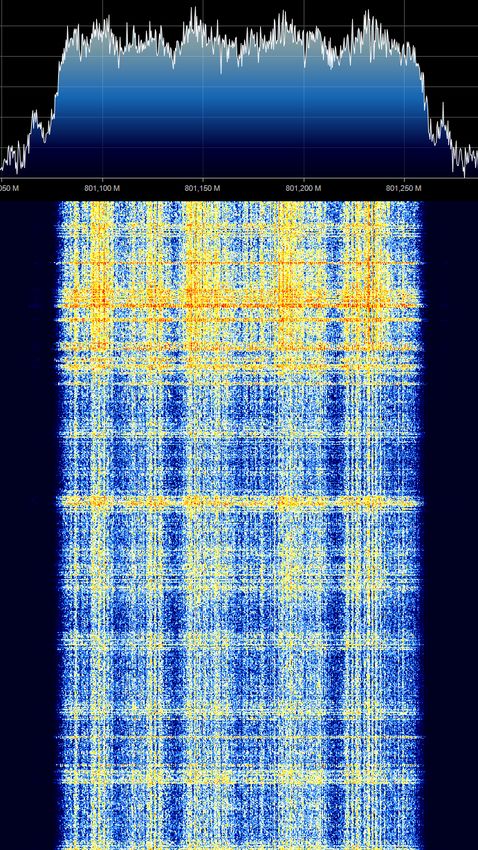
Sensors 2021, 21, 913                                                                                                 2 of 37

                              Environmental monitoring is a domain where large-scale remote sensing can help to
                        gain a better understanding in order to take more adequate measures to combat pollution
                        and climate change. For example, precision farming based on the analysis of the actual
                        conditions in the field can optimize the usage of fertilizers and agrochemicals, protecting
                        the soil and reducing costs, while increasing the crop yield. Another example application
                        is forest management. Forests and trees in general store carbon, retain water, contribute to
                        the conservation of biodiversity and to public health. They help to mitigate climate change,
                        and aesthetically support our well-being. Remote on-site monitoring of critical parameters
                        of trees [1], illustrated in Figure 1, contributes to a better understanding and helps to
                        predict the effects of climatic extremes on forests, urban trees and parks. The acquired
                        information can provide crucial input for climate-smart and sustainable decisions [2].

                        Figure 1. The ‘IoTree’ node [1] is designed and deployed for remote monitoring of a tree’s health.

                             Preventive conservation of cultural heritage can benefit from massive supervision
                        of artworks and their surrounding conditions. A low-power IoT node was designed to
                        monitor cultural heritage [3], and was deployed in the 17th century church of Santo Tomás y
                        San Felipe Neri in Valencia, Spain. It enables micro-climate monitoring of the environment,
                        in terms of temperature and humidity, to preserve the cultural heritage present in the
                        church and the construction of the church itself. Key requirements were to realize a low-
                        cost system to enable massive deployment, and a long battery life, that was estimated to
                        reach a lifespan of over 10 years with a single AA Lithium-ion battery. Furthermore, it was
                        important that the electronic devices could be embedded with as little aesthetic impact
                        as possible, and that they could be installed by people with no particular technical skills.
                        It should be noted that the connectivity is quite challenging as the radio waves need to
                        penetrate thick walls and cover large distances, a goal that was achieved by operating
                        on sub-GHz frequencies. Another customized system for monitoring the indoor climate
                        was designed and installed in Adriana’s house in Pompeii, Italy [4]. The system sampled
                        parameters every 30 min with 26 probes in 4 rooms for 372 days. Since the devices did not
                        feature wireless connectivity, rather cumbersome manual retrieval of data was necessary.
                             Monitoring, waste management, and asset tracking in cities can contribute signif-
                        icantly to goals that these have set to become smart and sustainable, and improve the
                        well-being of their inhabitants. The motivations for cities to embrace IoT technologies
                        are diverse and stringent, and to meet these demands, various applications have been
                        developed [5,6]. For instance, several solutions for remotely monitoring the status of
                        garbage bins have been realized [7–11]. In particular to combat food waste, several
                        IoT systems have been designed [12,13]. In the city of Suzhou, China, a solution encom-
                        passing edge devices, gateways, and cloud service, monitors the generation, collection,
                        transportation and final disposal of restaurant food waste [13]. The IoT nodes have a
                        reported lifetime of three years. In the context of improving sustainability and flexibility
                        of mobility, shared bicycle providers are deploying IoT-enabled electronic locks and local-
                        ization applications. Many other smart city applications have been realized, for example
                        energy efficient solutions for air quality monitoring [14].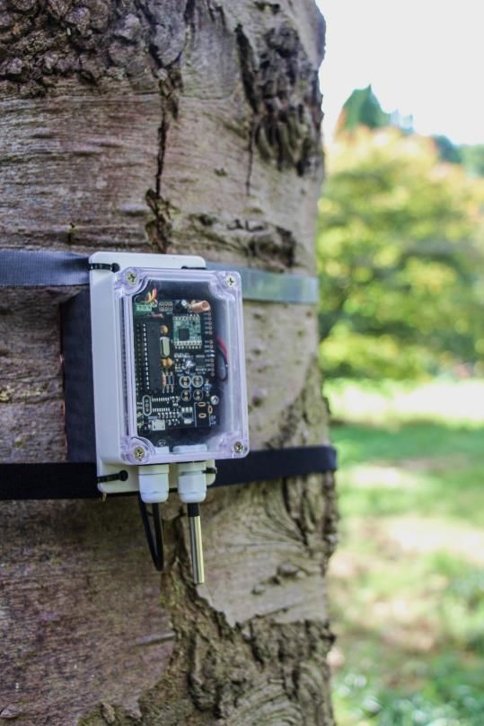
Sensors 2021, 21, 913                                                                                                   3 of 37

                             Industry 4.0 proposes a transformation to cyber manufacturing that heavily relies on
                        connected sensors to increase efficiency and flexibility [15]. In this context, IoT solutions are
                        deployed to optimize operation of a factory, ranging from predictive maintenance to asset
                        tracking. Logistic warehouses are getting more automated, based on remotely controlled
                        robots and IoT solutions to support the dynamism that is required to support the needs of
                        on-demand shopping and e-commerce, as well as to increase overall efficiency [16].

                        1.2. Challenges in Connecting Remote IoT Nodes
                             While the above use cases serve a variety of application domains, they require very
                        similar technological features and pose characteristic requirements to the overall IoT
                        architecture sketched in Figure 2. This architecture comprises (a) the IoT devices that
                        provide a sensing, measurement, and/or control functionality, (b) a wireless connection to
                        a gateway or base station for information exchange with the remote device, and (c) a server
                        or cloud platform where data can be stored, visualized, further processed and interpreted.

                                                (c)

                             (b)

                                      (a)

                        Figure 2. The typical architecture connects remote IoT nodes (a) via long-range connectivity to one of
                        more gateways or base stations (b). The interconnected gateways relay the information to the server
                        or cloud resources (c), where data can be visualized and interpreted.

                             The desired characteristics of long-range IoT systems, raising technological challenges,
                        can be found in three main categories and summarized as follows:
                        1.   Remote autonomous operation: Ideally the nodes can be installed following a ‘deploy-
                             and-forget’ approach, and are able to operate without short-term maintenance.
                             They should be able to run on limited energy reserves, or on energy harvested from
                             their environment. Ultimately, they will support self-management, including self-
                             diagnostic capabilities. Many applications can tolerate that a packet of information
                             gets delayed in delivery, or even sporadically gets lost.
                        2.   ‘Light’ IoT nodes: The nodes should come with a low complexity and a small price tag,
                             taking into account both hardware cost and communication plan. Their integration
                             often requires a small form-factor. They mostly need to perform periodic sensor
                             measurement (with a low duty cycle and non-time critical), with a-periodic time
                             critical events. Intelligence at the gateway and/or cloud can be relied on, and a
                             trade-off can be made in processing at the node or off-node.
                        3.   Large area deployment: the nodes get deployed in a wide range of environments,
                             in (sub-)urban as well as rural areas, and ranging from fields to forests. These ap-
                             plications require long-range wireless communication and have a low packet size.
                             Many application require awareness of the location of the devices [13], while the
                             devices themselves can operate more efficiently by exploiting knowledge on their
                             context [17].
                              This paper focuses on how to connect and design remote IoT nodes and operate them
                        as long as possible on a very restricted energy budget. It is essential to address challenges
                        in all three categories mentioned above: (i) autonomy, (ii) low-cost and small form-factor,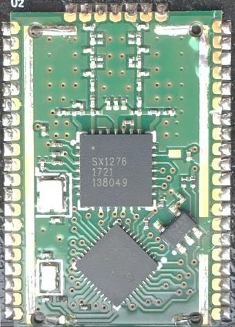
Sensors 2021, 21, 913                                                                                              4 of 37

                        and (iii) large area deployment capabilities. To maximize the autonomy of long-range
                        IoT devices, the energy budget needs to be managed meticulously, stingy, and correctly:
                        creative design of the nodes is desirable, creative (energy) accounting is unacceptable. To
                        estimate the expected energy need of IoT devices, the following approach can be taken:
                        1.     Make an inventory of operational modes of the device, including active and idle states,
                        2.     For each of the modes, estimate the power consumption of the node,
                        3.     Calculate the energy consumption by weighing the power consumption with the
                               expected time spent in these modes.
                              We illustrate this approach for a representative case in Figure 3. The results show,
                        in the first place, that the wireless transmitter is one of the big spenders. IoT applications
                        will require data to be sent from the device to the server, also called the uplink. This implies
                        that the device needs to provide the power to the radio signals to carry the data and spend
                        a relatively large time in this high power mode. This is in contrast to conventional mobile
                        communication networks which are in general downlink dominated. Figure 3 also shows
                        that, for sporadically active nodes, the sleep state has a high impact on the total energy
                        budget, even if power consumption is very low in this mode, as this mode is dominating
                        in time.

                                                                                         TX
                                                                                         (48.18 %)
                         TX
                         (72.64 %)

                                                                                                      Processing
                                                                                                      (0.02 %)
                                                                                                      RX
                                                                                                      (1.4 %)
                                                                 Processing
                                                                 (7.74 %)

                                                     RX
                                     Sleep           (19.74 %)                Sleep
                                     (0.035 %)                                (50.4 %)

                                      (a) Power consumption                         (b) Energy consumption
                        Figure 3. Power consumption and energy consumption share of each stage of a Long-Range Wide-
                        Area Network (LoRaWAN) node. The energy corresponds to reading out a sensor and send ing a
                        16 bytes payload packet (SF12) every hour [18].

                             This paper provides insights in what causes battery drain of remote IoT devices,
                        and proposes solutions to combat this. Selecting the right wireless technology is a first step
                        in this process. Hence, we zoom in to the current state of the art Low-Power Wide-Area
                        Network (LPWAN) technologies, in particular LoRaWAN, Sigfox and Narrowband IoT
                        (NB-IoT). As demonstrated earlier, communication requires a large share of a node’s power
                        consumption. As a consequence, battery preserving strategies such as, “think before you
                        talk” and, “race to sleep” are advocated. These strategies, however, only pay off when
                        combined with a careful hardware design. This design needs to ensure extremely low sleep
                        power, because the consumption in sleep largely determines the nodes autonomy. To that
                        end, we provide practical advise and illustrative examples that may help the embedded
                        system designer. We further point out emerging technologies and promising R&D that
                        may enhance the battery life of remote IoT nodes greatly in the future.
                             The remainder of this paper is organized as follows. In the next section we explain
                        the inherent physical dilemma in establishing long-range wireless connectivity while
                        keeping a low-power profile. We elaborate on approaches to overcome these, and sketch
                        the landscape of available LPWAN technologies. In Section 3, we present the typical
                        anatomy of an IoT node and we highlight the hardware design challenges to achieve a
                        long autonomy. Next, in Section 4, we elaborate on key strategies to preserving battery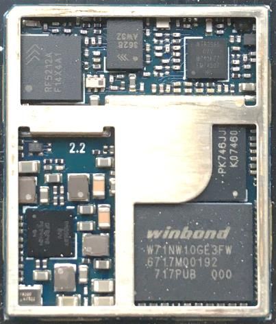
Sensors 2021, 21, 913                                                                                        5 of 37

                        life of remote IoT nodes. Finally, we summarize the conclusions of this overview paper in
                        Section 5 and we indicate promising R&D directions that can progress remote IoT nodes to
                        more and longer autonomy.

                        2. Low-Power Wide-Area Networks: The Technological Landscape
                              In this section we introduce the state of the art wireless communication technologies
                        to connect remote IoT nodes. In particular, we focus on energy-constrained devices that
                        require connectivity to the nearest access point or base station, at distances of hundreds
                        of meters to tens of kilometers. Complementary to other overviews [19,20], this survey
                        provides insights in transmission solutions to overcome the inherent discrepancy between
                        low-power and a large coverage. We further assess the landscape of current IoT technolo-
                        gies, considering energy consumption in conjunction with communication characteristics.
                              The most prominent requirements for serving remote IoT nodes are long-range and
                        low-power connections. Consequently, this paper focuses on Low-Power Wide-Area
                        Networks (LPWANs) which are tailored to provide wide-area communication to power-
                        constrained devices. LoRa [21] and Sigfox [22] are both LPWAN technologies which gained
                        popularity in recent years and are now key players in this domain each bringing specific
                        interesting features. These technologies operate in the unlicensed sub-GHz spectrum due
                        to the favorable propagation characteristics needed for coverage extension. Furthermore,
                        new cellular communication modes and terminal categories are defined, e.g., NB-IoT [23],
                        for Machine-Type Communication and IoT applications. NB-IoT can operate both in sub-
                        GHz and conventional cellular frequency bands. Notably, other technologies exist but are
                        less adopted by the LPWAN vendors or are focused on higher throughput communica-
                        tion. For instance, two other cellular technologies are designed to support machine-type
                        communication. EC-GSM extends the coverage of legacy Global System for Mobile Com-
                        munications (GSM) but is less or not adopted by network vendors. In addition to NB-IoT,
                        another technology based on Long Term Evolution (LTE) is specified, i.e., LTE-M. This
                        standard, while less adopted than NB-IoT, also targets a different market, i.e., Machine-
                        to-Machine (M2M). Furthermore, other technologies tailored for LPWAN communication
                        such as RPMA, NB-Fi, Weightless, Wi-Fi Halow, DASH7 have seen less of an adoption by
                        the LPWAN market and are therefore not further considered in this work.
                              Long-range and low-power connections require the co-design of both the physical [24]
                        and medium access control layer [25]. The Physical (PHY) layer defines the modulation
                        scheme applied to get bits of information transported by Electromagnetic (EM) waves.
                        The Medium Access Control (MAC) layer specifies the manner in which the devices or
                        nodes access the shared medium, i.e., the radio band. It coordinates the access to mitigate
                        and minimize packet collisions and interference. An optimized design in both layers is
                        required to achieve low-power operation. This section elaborates on the aspects by which
                        the technologies address the low-power and long-range constraints. We first describe the
                        possible design approaches at each layer. After which, the specific implementation of these
                        approaches by each technology is further discussed. A summary of the design choices of
                        each of these technologies can be found in Table 1.
Sensors 2021, 21, 913 6 of 37
Table 1. Overview of approaches of LPWAN technologies to address long-range and low-power requirements. The PHY
and MAC is simplified in order to transmit small packets at a low data rate and low transmit power.
LoRaWAN Sigfox NB-IoT
PHY
Modulation scheme CSS D-BPSK BPSK/QPSK (SC-FDMA)
Frequency 868 MHz 868 MHz GSM (e.g., 900 MHz) LTE
(e.g., 1700 MHz)
Bandwidth 250 kHz and 125 kHz 100 Hz 200 kHz
Transmit Power (dBm) ISM governed: max. 14 (node) /27 (gateway) 14/20/23
MAC
Protocol overhead
Initial Access None (ABP)/Low (OTA) None High
Uplink Packet 13–28 bytes 14 bytes IP-based (depends on higher
layer protocols)
Collisions
Freq. div. No Yes
Space div. Yes Yes n.a. (grant-based)
Time div. No Yes
Overhearing No No No (grant-based)
Adaptive PHY control Yes (ADR) No Yes (CE levels)
Maximum payload size ∼250 bytes 12 bytes 1600 bytes
2.1. How Can LPWAN Technologies Communicate on a Low-Energy Budget?
LPWAN technologies adopt simple yet adequate modulation schemes and energy-
efficient MAC principles to support low-power operation. As illustrated in Figure 3,
transmitting has a high impact on the energy consumption of the node. The energy
required in the radio to transmit the information accounts for a share of almost 50% of the
total energy consumption. Hence, this is addressed by LPWAN technologies to reduce the
energy expenditure of an IoT node.
2.1.1. Low-Energy Physical Layer
Increasing the spectral efficiency was the main focus during the evolution of con-
ventional communication technologies. Over different generations, going from 2G to 3G
and 4G, this has been achieved by condensing the information per Hz. Information is
digitally modulated and can be represented by constellation points on a complex plane, as
shown in Figure 4 [26]. The more constellation points, the larger the alphabet of symbols
that can be carried by a single sample. The length of this alphabet, i.e., the number of
different symbols, is called the modulation order. To increase the spectral efficiency, higher
order modulation schemes are used, densifying the constellation points. This makes these
schemes more error prone than lower-order modulation, as additive noise at the receiver
will provoke wrong decisions on which point constellation was actually transmitted. As a
consequence, high throughput technologies require a high Signal-to-Noise Ratio (SNR),
which is achieved either by transmitting over short links or with a significantly high power
level. None of these are feasible for remote IoT devices. To tackle this, LPWAN technologies
adopt more robust but less spectral efficient modulation schemes. The impact of the SNR
on the constellation points is depicted in Figure 4. We illustrate the sensitivity to Additive
White Gaussian Noise (AWGN) for Binary Phase Shift Keying (BPSK), transmitting one bit
per symbol with a 2-symbol alphabet, and 64 Quadrature Amplitude Modulation (64QAM),
transmitting six bits per symbol with a 64-symbol alphabet [26]. Here, we adopted typical
SNR values [27] for long-range (−20 dB at 4 km) and a short-range (6 dB at 20 m) connec-
tions. LTE (4G) defines a good quality link if the SNR is equal or higher than 20 dB. This is
used as a baseline for comparison.Sensors 2021, 21, 913 7 of 37
Transmitted Symbols 20 dB 6 dB −20 dB
1 1 1 1
BPSK
0 0 0 0
−1 −1 −1 −1
−1 0 1 −1 0 1 −1 0 1 −1 0 1
100% 99.5% 58.7%
1 1 1 1
64 QAM
0 0 0 0
−1 −1 −1 −1
−1 0 1 −1 0 1 −1 0 1 −1 0 1
95% 18.0% 1.5%
Figure 4. Constellation diagrams of BPSK and 64-QAM modulated symbols at different SNRs
including the percentage of successfully demodulated symbols. It demonstrates that low-order
modulation schemes are vital in order to work in low-SNR environments or when the transmit power
levels are low.
Figure 4 demonstrates why low-order modulation schemes are required for low
SNR scenarios. Furthermore, the usage of low-order modulation schemes allows for less
complex hardware, reducing the power consumption of the radio hardware. In particular
for transmitting complex signals over a long range, the power amplification stage takes
up more than 70% of the power budget, and achieves an efficiency of typically less than
30% because of the need to operate with significant back-off [28–30]. A power amplifier
amplifies an input signal to a higher power signal. This amplification needs to be linear
in order to not introduce distortions in the outputted signal. However, practical power
amplifiers have a non-linear region close to their saturation point, causing distortions.
The power level of the input signal is lowered to mitigate operating in this non-linear
region. The higher the dynamic range of the input signal, i.e., the Peak-to-Average Power
Ratio, the higher the required back-off. A PA is most efficient when working close to the
saturation point. As a result, the PA is performing in a non-efficient manner due to the
required back-off.
LPWAN technologies mitigate this inefficiency—in power consumption—by using
constant envelope modulation schemes, where the amplitude of a signal is kept constant.
To illustrate, Frequency-Shift Keying (FSK) transmits with an alphabet of symbols that have
different discrete frequencies of their carrier signal [26]. This scheme does not alter the
amplitude of the signal, relaxing the PA constraints. Furthermore, due to the reduced the
data rate LPWAN technologies limit the payload size in order to lower the transmit duration.
Besides a low payload size, the transmission power is also limited in the unlicensed bands–
to respect the regulations.
Implementations in LPWAN
Each technology adopt different strategies, e.g., wideband vs. narrowband. This
is illustrated in Figure 5 where a measured waterfall spectrum of a LoRaWAN, Sigfox
and NB-IoT message is depicted. In LoRaWAN, Long Range (LoRa) and FSK are used at
the PHY layer operating at 433 MHz and 868 MHz in Europe. Other frequency bands are
used in different regions, please consult the frequency plan based on your region. FSK
is used for short-range communication. The LoRa modulation scheme is based on Chirp
Spread Spectrum (CSS). This technique encodes a single bit to multiple chirps. A chirp is
a sinusoidal signal where the frequency is linearly increased or decreased in time over a
fixed bandwidth. The spreading factor determines the duration of the chirps and hence the
data rate. In other words, by increasing the spreading factor, the energy per bit is increased.
This subsequently improves the SNR, yielding a higher sensitivity. The receiver sensitivitySensors 2021, 21, 913 8 of 37
is a measure of the minimum required received Radio Frequency (RF) power to be received
in order to be still able to demodulate the signal. A trade-off between range and energy
consumption can be made by changing the spreading factor. Due to the additional gain by
spreading the signal and having a constant amplitude envelope, inexpensive low-power
high-efficiency PAs can be used.
In contrast to LoRaWAN, Sigfox uses an ultra narrow-band modulation scheme.
Data is modulated by Differential Binary Phase Shift Keying (DBPSK) at 100 bps, generating
a 100 Hz signal. Opposed to BPSK, where symbols are directly mapped to the constellation
points, DBPSK modulates symbols by phase shifts. For example, a binary 1 results in a 180°
shift, while 0 does not introduce a phase shift. The system is more resilient against phase
noise, as phase shifts are used rather than fixed constellation points. NB-IoT is mainly a
slimmed-down version of LTE and reuses the modulation techniques employed in LTE [31].
In the uplink, NB-IoT uses BPSK or Quadrature Phase Shift Keying (QPSK) depending
on the coverage [32]. The devices are multiplexed with Single-Carrier Frequency Division
Multiple Access (SC-FDMA). In contrast to Orthogonal Frequency Division Multiple Access
(OFDMA), SC-FDMA yields a lower Peak-to-Average Power Ratio (PAPR) [33] and thereby
a lower back-off is required, resulting in a more power efficient PA operation. As a high
share of the energy drain is a result of the transmission stage, in NB-IoT lower power classes
are defined [23], i.e., 23 dBm (Power Class 3), 23 dBm (Power Class 5) and 14 dBm (Power
Class 6). Power class 6 was recently introduced in 3GPP Release 14 [34]. These classes allow
to simplify the PA and battery requirements thanks to the lower transmit power. While
this brings a clear benefit for IoT devices, currently deployed networks are not prepared
for these low-power transmissions and therefore these devices can be forced to employ a
higher coverage extension, as further discussed in Section 2.2.
(a) LoRaWAN (125 kHz) (b) Sigfox (100 Hz) (c) NB-IoT ( 180 kHz)
Figure 5. Measured waterfall spectrum of LoRaWAN, Sigfox and NB-IoT. The vertical axis represents
the time and the horizontal axis the frequency domain. Due to the difference in time and frequency
allocation, the figures have not the same time and frequency scale. The observed spectral leakage is
due to the Fast Fourrier Transfomation (FFT) operation.
2.1.2. Low-Energy MAC Layer
Collisions, overhearing or idle listening, and overhead are the main causes of energy
drainage related to the MAC layer [25]. Collisions occur when two nodes transmit and
the signals overlap in time and frequency whereby the intended receiver is unable to
demodulate the packet. Consequently, the energy consumed by both transmitter and
receiver was wasted. Idle listening or overhearing is caused when a device is listening forSensors 2021, 21, 913 9 of 37
downlink communication when there is none. Lastly, overhead due to additional signaling
or protocol overhead introduces an extra energy drain. To address these issues, LPWAN
technologies apply simple MAC schemes, as illustrated in Figure 6. The communication is
mostly device-initiated, meaning that an uplink message is transmitted when the device has
some data to send. The remainder of the time the device is kept in sleep mode. Overhearing
and idle listening is particularly important in technologies operating in the unlicensed
bands where everyone—respecting the regulations—can freely communicate. By specifying
the start of a receive window, idle listening is kept to a minimum. Furthermore, no or
limited signaling is used to request access to the network and the protocol overhead is
constrained to the bare minimum in order to send small-sized packets over the network.
As most applications allow for a packet loss to a certain degree, these protocols often
follow a ‘fire-and-forget’ approach where collisions are of insignificant importance. As a
result, the use of acknowledgments and retransmissions is less common and application-
dependent.
(0-12 Byte)
Payload
Header
Uplink Downlink
message message
Time
Figure 6. Typical MAC scheme for remote IoT devices. The communication is mostly device-induced
with a limited payload and minimized protocol overhead. While downlink communication is
supported, it is mostly restricted to a couple of messages per day.
Implementations in LPWAN
Both Sigfox and LoRaWAN operate in the unlicensed bands and follow a ‘fire-and-
forget’ approach. They do not employ any multiple-access technique, i.e., ALOHA. They
rely on collision avoidance techniques such as repetitions and narrow-band signals in Sig-
fox [35], and spread-spectrum in LoRaWAN to mitigate interference. Therefore, LoRaWAN
and Sigfox are best effort LPWAN protocols without any guaranteed delivery. Notably,
LoRaWAN supports acknowledgments and retransmissions to a certain degree.
Moreover, both technologies specify the time and frequency of a receive window in
order to limit idle listening. LoRaWAN (Figure 7a) opens a first receive window one second
after the uplink message, where the downlink message has to use the same spreading factor
and frequency of the transmitted packet. In case no preamble is detected, a second window
is opened two seconds after receiving the uplink message at a default frequency and spread-
ing factor. The default frequency (or channel) and spreading factor is 869.525 MHz and
SF12 [21]. However, networks opt to use lower SFs in order to decrease the duration of the
receive window. Both Casals et al. [18,36] have observed that requesting a retransmission
can lower the overall energy consumption because the node does not open a second receive
window after detecting a downlink message in the first window. For this purpose—and
more extreme—Thoen et al. [1] propose to force the node in sleep mode without opening
any receive windows. Similarly, Sigfox also supports bidirectional communication, while
restricted to a maximum of four downlink messages per day. In contrast to LoRaWAN,
Sigfox opens only one receive window (Figure 7b). After receiving a downlink message,
the device responds with an uplink confirmation message [37].Sensors 2021, 21, 913 10 of 37
RX Downlink Downlink
wind. 1 message message
Time Time
1s 500 – 525 ms
2s 20 s
25 s
(a) (b)
Figure 7. Medium Access Control mechanism for LoRaWAN and Sigfox. (a) LoRaWAN opens two receive windows after
a transmit message. The first window utilizes the same data rate as the transmit message. The second window employs
more robust settings to increase the chance of reception. (b) Sigfox transmits three duplicates at different frequencies and
different time instances. Limited downlink is possible and is received at the initial transmit frequency plus an offset.
NB-IoT, as a derivative of LTE, employs a more complex random access procedure [38].
The node first has to request access prior to transmitting an uplink message. The base
station responds with a time and frequency slot where the node gets the opportunity
to transmit. Furthermore, in contrast to the other technologies, NB-IoT is fully bidirec-
tional, and not uplink-focused. Both node-terminated (paging) and node-induced traffic
is supported, as illustrated in Figure 8. As paging and maintaining an active connection
can be highly energy consuming, NB-IoT introduces Extended Discontinuous Reception
Mode (eDRX) and Power Saving Mode (PSM). Both mechanisms are depicted in Figure 8.
Extended Discontinuous Reception Mode allows a node to listening less frequently to
downlink messages. These values are provider-specific, but they have to support at least
an eDRX time of 40 min [39], compared to the maximum of 2.56 s in LTE. A higher energy
reduction is achievable by employing PSM. In PSM the node notifies the network that it
is going dormant and negotiates the duration of the hibernation. During this period, the
node cannot receive any downlink messages but can transmit a packet without having to
reconnect to the network. The maximum allowed time is 413 days [39]. In this manner,
applications sending one packet per day can configure a PSM of 1 day. In case a critical
message has to be sent, the node can initiate a transmission without having to wait till the
end of the agreed-on hibernation period.
Power
Power
Data transfer
Data transfer
Data transfer
? ?
? ? ? ? ? ?
Extended
DRx
Paging
Paging
Paging
PSM
Sleep Sleep
Time Time
(a) (b)
Figure 8. Energy saving strategies employed in NB-IoT, i.e., Extended Discontinuous Reception Mode and Power Saving
Mode, respectively. (a) Listen more infrequently to downlink message with eDRX. (b) Hibernate between data transmissions
with PSM.
Prior to transmitting messages, nodes have to join a network. This initial access
overhead is minimized in LPWAN. Sigfox does not use any joining procedure, while
LoRaWAN supports both non-initial access and initial access protocols, i.e., Authentication
By Personalisation (ABP) and Over The Air Authentication (OTAA), respectively. In
NB-IoT, a node has to register to the network after a power-down. Fortunately, through
PSM a node does not have to re-join to the network after a wake-up.Sensors 2021, 21, 913 11 of 37
2.2. How Can LPWAN Technologies Achieve a Long-Range Connection?
LPWAN technologies extend the communication range also by a co-design of PHY
and MAC layer approaches: (1) utilizing low frequency bands with favorable propagation
characteristics, (2) applying modulation schemes which are less sensitive to a low SNR,
(3) adopting MAC schemes to increase the probability of successfully receiving a packet
and (4) dynamically adapting to the link conditions.
2.2.1. Long-Range Physical Layer
In order to extend the range, LPWAN technologies utilize sub-GHz frequencies.
The benefits of lowering the carrier frequency is illustrated by the Friis transmission
Equation (1) [40]. The received and transmit power is denoted by Pr and Pt , respectively.
The directivity of the antenna is represented by D. The directivity of an antenna is angle-
dependent. Hence, the directivity in the Friis formula depicts the directivity in the direction
of the other antenna. The distance between the transmitter and receiver is denoted by
d. The wavelength of the signal is expressed by λ. In other work, the antenna gain (G)
is sometimes used instead of the directivity (D). As this expression is defined for ideal
scenarios both expressions are equivalent as we have an antenna efficiency e of 1 and
G = eD. The formula demonstrates that the received power (Pr ) is proportional to the
square of the wavelength (λ). To be complete, the received power depends on the effective
area or aperture of the antenna. This area describes the amount of power captured from
the EM wave impeding on the antenna and is depending on the wavelength. It shows
that more energy is transferred at lower frequencies due to the larger antenna aperture.
Therefore, the path loss, defined as the ratio of the received power to the transmitted
power, is also dependent on the wavelength. While this formula is defined for ideal
free-space conditions, this frequency-depended path loss also holds in real environments.
Moreover, objects appear smaller and have less impact of the signals at lower frequencies
because the wireless propagation of the signals is affected by the objects relative to the
signal’s wavelength.
λ 2
Pr
= Dt Dr (1)
Pt 4πd
As illustrated in Figure 4, low-complexity modulation is better suited for low SNR
scenarios. In addition, the transmit power of the nodes can be lowered in case the SNR is
higher than required. In other words, reducing the data rate increases the sensitivity of the
receiver and thereby extends the coverage.
Implementations in LPWAN
LoRaWAN, Sigfox and NB-IoT operate at lower frequencies to benefit from the favor-
able propagation and adopt low-order modulation schemes. The range can be extended in
LoRaWAN by increasing the spreading factor, thereby lowering the demodulation floor.
For example, with a spreading factor of 12 a signal with an SNR above −20 dB can be
demodulated, while for SF7 a minimum SNR of −7.5 dB is required in order to demodulate
the packet. NB-IoT on the other hand switches between demodulation techniques, i.e.,
BPSK and QPSK, depending on the link condition.
2.2.2. Long-Range MAC Layer
LPWAN technologies use diversity techniques to increase the probability of success-
fully receiving a packet: time, spatial and frequency diversity. In other words, by transmit-
ting on different frequencies, at different time instances and by using multiple receivers,
the probability that a packet is lost is lowered. To further increase the probability of
successful receiving a packet, the PHY layer is controlled and adapted to the current
link conditions.Sensors 2021, 21, 913 12 of 37
Implementations in LPWAN
As an instantiation of applied diversity techniques, Sigfox sends three duplicates of the
same packet, as depicted in Figure 7. Each packet is sent on another frequency at another
time instance. Sigfox operators also try to densify the network so that all packets are
received by at least three gateways. In contrast to Sigfox, LoRaWAN and NB-IoT employ
mechanisms to adapt to the channel conditions. In NB-IoT three CE levels are defined,
i.e., normal, robust and extreme. In the highest CE level (CE level 2) 128 repetitions,
a higher power class 23 dBm and single tone transmissions are utilized to extend the
coverage. The maximal tolerable loss or Maximum Coupling Loss (MCL) is defined for
each of these coverage levels, i.e., 144 dB, 154 dB, 164 dB. Equivalently, in LoRaWAN the
ADR algorithm [41] alters the spreading factor and transmit power to accommodate for
more losses in channel. Furthermore, different spreading factors yield orthogonal packets,
e.g., a SF7-modulated packet is not interfered by a SF12-modulated packet. By adopting
ADR, the utilized spreading factor in the network is optimized, thereby reducing the
number of collisions.
3. Anatomy of an Internet of Things Node
The typical anatomy of an IoT device, and its building blocks, is shown in Figure 9.
It consists of a controller, a wireless radio module, sensor(s) and an energy source. In the
following paragraphs we discuss each of these components and highlight the important
properties that are needed for IoT devices to operate while using as little energy as possible.
The strategies to achieve this, are discussed in Section 4.
Energy harvest
Power manager
Energy storage
Controller
Sensor
Core and memory
Clock management
Physical world
Analog
AD Converter
Front-end
Energy management
Serial communication
Actuator
I/O ports
Radio module
Timers and triggers
RF Analog interfaces
Protocol stack
Front-end
Security
Figure 9. Generalized architecture of an IoT node. The complete device is typically battery-powered,
optionally assisted by some kind of energy harvesting technology, e.g., a solar panel. Sensors periodi-
cally sample the environment for information, which is transmitted wirelessly. A microcontroller has
all the amenities to manage the operation and behavior of the node. Actuators, e.g., a LED, allow the
node to influence its environment or signal the user.
3.1. Controller
The IoT node’s operation is controlled by the microcontroller by executing embedded
software, also referred to as firmware. Core clock frequencies can range in order of
magnitude from 10 kHz to 100 MHz. The clock frequency affects both processing speedSensors 2021, 21, 913 13 of 37
and power consumption (see Section 4 for more details). Control over the node’s embedded
hardware is facilitated by the controller’s broad range of built-in peripherals. General-
Purpose Input/Output (GPIO) allows for driving basic digital signals, e.g., enable/disable
subsystems, as well as reading from them, e.g., status indicators. Hardware support
for digital serial protocols [42], such as, Serial Peripheral Interface (SPI), Inter-Integrated
Circuit (I2C) and RS232 help with interfacing with subsystems such as, the radio module
or the sensors.
Equivalent to the digital communication protocols, analog interfaces are present on a
controller to interface with analog sensors. An important example is the built-in Analog-to-
Digital Converter (ADC), which omits the need to include an external ADC on the node’s
Printed Circuit Board (PCB). To secure the radio communication, dedicated security blocks
are often integrated in the controller enabling acceleration of encryption algorithms. For
example, Silabs’ EFM32TM Arm Cortex-based line of microcontrollers integrate hardware
acceleration, among others, for AES, SHA and ECC. Timers, whether or not independently
clocked, allow for time-keeping and periodic event firing, e.g., to periodically initiate a
sensor measurement. Finally, several features specifically aid in energy management of
the controller itself. Power for different subsystems can be enabled or disabled and the
clock speed can be throttled. The core itself can be put in sleep, while some peripherals
remain active. The controller’s interrupt system can wake-up the core when an event
occurs, e.g., A timer fires, or even initiate data transfer between two peripherals, bypassing
the core altogether. This is the so-called Peripheral Reflex System (PRS) system, a network
that lets the different peripheral modules communicate directly with each other without
involving the core [43].
3.2. Sensor
A rich variety of phenomena and signals can be observed using a broad selection of
sensors, using different operating principles [44]. Today, the choice is nearly unlimited.
Several selection criteria can be applied when choosing a sensor with a certain application
in mind. Common functional specifications such as supply voltage and required PCB
real-estate are highly application dependent. Choosing a sensor that is able to operate on
the same supply rail as the microcontroller, generally simplifies the interfacing between
the two.
Digital versus analog. In cases where raw, unprocessed sampling is required, an ana-
log sensor is to be preferred over a digital sensor. Moreover, when ultra-low power
operation is required, an analog solution can be advantageous. However, the design of the
analog front-end that is responsible for signal conditioning, e.g., amplification or filtering,
increases development time, and creates new challenges in terms of power management.
Digital sensors, typically connected to the controller using I2C or SPI [42], can simplify
the hardware design process significantly. Multiple sensors can be connected to the same
I2C-bus, effectively saving pins on the microcontroller. Sensing element, analog front-end
and additional logic circuits are integrated on the same device. When the sensor readings
are (pre-)processed on-chip before communicating with the microcontroller, it is referred
to as a smart sensor [45]. A typical and quite handy example is an Inertial Measurement
Unit (IMU). For example, the ADIS16488A IMU is a complete inertial system that includes
gyroscope, accelerometer, magnetometer, and pressure sensor readings. The factory cal-
ibration characterizes each sensor individually and programs it with its own dynamic
compensation formulas in order to provide accurate sensor measurements [46].
When selecting a digital sensor, a type with certain integrated features is preferable,
as these features will help to implement some energy-saving strategies (see Section 4).
Examples of such features are:
• A sleep or power-down function simplifies power management,
• Automatic sampling (with programmable period) omits the need for extra communi-
cation with the microcontroller, i.e., it does not continuously need to “tell” the sensor
to start a new measurement,Sensors 2021, 21, 913 14 of 37
• Programmable thresholds can further reduce communication between the sensor and
the controller. For example, an accelerometer will only signal the controller when the
measured acceleration is above a certain G-force.
Keep in mind that, to facilitate these smart functions, additional signals are often
required. For example, an alert pin on a sensor (indicating that measurements have
exceeded a set threshold), needs to be connected to one of the microcontroller’s inputs.
What and how to measure? While some applications require only measurements of a
single parameter, many, e.g., environmental monitoring, involve the collection of several
parameters. It is common to find sensors that integrate a set of related measurements.
For example, the BME680 is a digital low-power gas sensor that is able to measure air tem-
perature, humidity and pressure, specifically suited for indoor operation [47]. Furthermore,
it is able to detect Voltatile Organic Compounds (VOCs), making it suitable as an (indoor)
air quality sensor.
Quite often applications need knowledge of where the measurement(s) take place.
If sensor nodes are mobile, or if deployment is random, e.g., by an airdrop, the position
of the sensor is a measurement in its own right. To locate an IoT node, an obvious course
of action is to incorporate a Global Navigation Satellite System (GNSS) receiver into the
device. A GNSS receiver can locate the node by using one of the GNSS satellite systems
(e.g., Global Positioning System (GPS) or Galileo). The module can compute a real-time
position using satellite information: latitude, longitude and altitude within a radios of 10 m
or better [48]. However, localization comes with an non-negligible energy cost due to the
long setup time. More energy-efficient approaches exist by using native geolocalisation
based on the uplink messages. The advantage of this approach is that this information
comes “free”, i.e., it can be extracted from the communication needed to send the sensor
measurements. This is further discussed in Section 4.2.2.
3.3. Radio Module
The radio module is responsible for exchanging information wirelessly. Depending
on the IoT technology, two options are available, i.e., a transceiver or a modem (Figure 10).
The former supports only the PHY layer of the protocol. Often, the RF front-end, including
also the PA, is integrated on chip. The MAC layer needs to be implemented on the
controller. A (wireless) modem, on the other hand, simplifies interfacing by implementing
both the PHY and MAC layer. A modem is typically controlled by means of ATtention
(AT) commands. The benefit of using transceivers, is that only one microcontroller is
present on the device, while the modem also incorporates a controller to handle the
MAC. Although these embedded controllers are also ultra low-power, it still yields a non-
negligible energy penalty, as can be observed in Table 2. Despite this, modems significantly
lower the development effort as no MAC layer protocol has to be implemented on the
microcontroller. This also ensures that the node respects the protocol specification. Both
approaches are sometimes combined where the microcontroller—in the System on Chip
(SOC)—can be directly programmed with user-specific code. For example the Nordic
NRF52832 allows to program the internal Arm while still retaining the protocol stack.Sensors 2021, 21, 913 15 of 37
RF Front-end with amplifier RF Front-end with amplifier
RF Front-end and transceiver and transceiver
Qualcomm MDM9206 LTE Qualcomm MDM9206 LTE
SX1276 Transceiver
Modem Controller
Power management Power management
PIC18LF46K22 8-bit MCU Flash memory Flash memory
(a) Components inside the Microchip RN2483 LoRaWAN mo- (b) Components inside the Quectel BG96 NB-IoT modem.
dem.
Figure 10. Modems combine RF front-end, transceiver and MAC layer implementation on a controller in one easy to use
module. These examples show the internal components of two popular IoT modules. While the building blocks of these
modules are independent of their manufacturer, these modules are chosen because of their high availability and adoption in
IoT nodes.
Table 2. Examples of IoT development platforms.
MKR WAN 1300 The Things Uno Seeeduino ST B-L072Z-
LoRaWAN LRWAN1
Host MCU SAMD21 ATmega32u4 ATSAMD21 STM32L0
MCU Architec- Arm M0+ AVR 8 bit Arm M0+ Arm M0+
ture
MCU Clock 48 MHz 16 MHz 48 MHz 32 MHz
speed
Modem Murata CMWX1 Microchip RisingHF RHF76 Semtech SX1276
RN2483
Operating volt- 3.3 V 5V 5V 3.3 V
age
Power usage Low High Medium Low
Price indication e 33 e 55 e 47 e 42
Note that the ST B-L072Z-LRWAN1 features the Murata CMWX1ZZABZ-091 module, integrating both microcon-
troller, modem and RF front-end on one module.
Controller
External voltage Internal voltage Central Processing Unit (CPU)
regulators regulators
Power
Management External
Unit (PMU) Memory Subsystems
oscillators oscillators
Internal Peripherals
Figure 11. The internal Power Management Unit (PMU) of a microcontroller supervises other
Microcontroller Unit (MCU) building blocks. Depending on the current controller state, different
voltage regulators are connected or disconnected. The firmware on the CPU can, in turn, enable or
disable external subsystem, such as, sensors or the modem.
3.4. Power Management
Power management on the IoT node falls into two main parts. A first part is the
voltage regulation, which ensures that the voltage input, either from the battery, energy
harvesting or any other power source, is converted into the operating voltage for the node’s
electronics. Most often this includes a Low-Dropout Regulator (LDO) voltage converter or
switching mode voltage regulator. Please note that these electronics might require differentSensors 2021, 21, 913 16 of 37
operating voltages. In any case, these voltages are distributed to the controller and all
peripherals through the so-called supply rails.
A second part is the power switching, which is typically governed by the firmware
running on the Central Processing Unit (CPU) (see Figure 11 for the blocks involved).
The power switching, in turn, falls into two parts. Firstly, the external subsystems, such as
sensors, modem or even complete supply rails, can be enabled or disabled by the CPU.
This typically involves load switches or control signals that are connected to the controller’s
GPIO. Of course, such type of control requires that the appropriate measures are taken
when designing the hardware (see Section 4.1.2).
The power inside the controller is managed through the PMU. One task of the PMU
is providing a constant supply voltage to components inside the controller. Another task
of the PMU is to control power distribution inside the controller, i.e., cut-off or provide
power to certain blocks. By doing this, different power states are supported each providing
different features. For the well-known Arm-based types of microcontrollers, that are
much-used in IoT designs, these are the so-called energy modes.
3.5. Energy Storage
Most remote IoT nodes rely on batteries as an energy storage and provisioning solution.
The most commonly used battery technologies are discussed in this section, summarizing
their main relevant characteristics in view of the specific requirements of IoT devices.
Other energy storage technologies exist but are less suitable for IoT devices. For example,
current state of the art Electric Double-Layer Capacitors (EDLCs) have a high self-discharge
yielding this technology unsuitable for long-lived applications. Rechargeable batteries,
on the other hand, are especially suited in combination with energy harvesting techniques.
Lithium Cobalt Oxide (LCO) and Lithium Polymer (LIPO) batteries are currently the most
used rechargeable technologies. The attractiveness of such batteries is limited mostly due
to their constrained operating temperature, as their capacity is severely impacted by the
temperature. In addition, LCO and LIPO have a higher self-discharge rate compared
to non-rechargeable batteries. This self-discharge limits the autonomy of IoT devices.
Non-rechargeable batteries, while being one time usable only, have some favorable prop-
erties compared to the above rechargeable batteries, not in the least their self-discharge
rate. The generally higher energy density and operating temperature makes them more
suitable for deploy-and-forget IoT applications. To support a long operating time, the
considered battery technologies have a capacity in the order of several ampere hours.
Battery technologies such as Silver oxide, Zinc Air and Zinc Cloride, typically packaged in
small button cells, have a lower capacity [49] and are therefore not included in this study.
The various parameters that are vital for remote IoT nodes are discussed below and
grouped by their impact. Table 3 shows various energy storage technologies and their
characteristics based on the manuals of corresponding battery compositions. By selecting
the most optimal battery technology, the node’s operation time is maximized. As a result,
the batteries of these devices require less battery changes and hence less maintenance,
further reducing the impact on the environment.Sensors 2021, 21, 913 17 of 37
Table 3. Overview of the most commonly used energy storage technologies for IoT applications. The discharge rate is
described by the C rate. A battery with a C rate of 1 and a capacity of 1 A h can supply 1 A for 1 h.
Non Rechargeable Rechargeable
Composition Alkaline Lithium Lithium Lithium Lithium Lithium Lithium
Thionyl Man- Iron Poly Cobalt Polymer
Chloride ganese Disulfide Carbon Oxide
Dioxide
Abreviation ALK [50] LTC [51] LMD [52] LID [53] PC [54] LCO [55] LIPO [56]
Volumetric energy density Wh/L 506 1080 683 562 532 602 309
Weight energy density Wh/kg 176 480 323 300 300 217 185
Power density W/kg 18Sensors 2021, 21, 913 18 of 37
inside the controller voltage range. This can be achieved by implementing an LDO voltage
converter or a step down switching voltage converter.
Faster discharge rates result in more internal losses, voltage drops, and a lower usable
battery capacity. Therefore, the maximum recommended discharge rate will be defined by
the manufacturers. For most battery technologies, IoT nodes will not exceed this limit.
3.5.4. Operating Temperature
Depending on the temperature range and conditions the nodes will be deployed in,
the operating temperature of the battery may be an important characteristic. While the self-
discharge generally will be lower at low temperature, the battery capacity and cell voltage
will decrease. Lithium Thionyl Chloride (LTC) non-rechargeable batteries can operate in
a wide temperature range and are most resistant to extremely low temperatures–down
to −55 °C. Only high loadsSensors 2021, 21, 913 19 of 37
3.6. Energy Harvesting
Energy harvesting facilitates energy provision during deployment, prolonging the
autonomy of devices—theoretically even to an unlimited time. Several sources of en-
ergy can be harvested from, either in the ambient environment or from external sources.
Ambient sources are available/in the air spontaneously, while external sources of energy are
deliberately delivered to devices. Recently energy harvesting solutions are also designed
specifically for small IoT devices [10,66]. We here only provide brief comments on the scala
of technologies, and refer the readers to the many publications that provide an overview of
technologies [67–69]. Typical values for energy harvesting sources such as solar, vibration,
thermoelectric and radio frequency energy are depicted in Figure 12. Please note that this
provides an indicative relation only, as a power density is not a straightforward metrics for
all the considered technologies. The employed energy harvesting technique will primarily
be determined by the application itself and the environment where it is deployed.
3.6.1. Sun and Light Sources
Light sources are providing energy via radiation that can be harvested based on the
Photovoltaic (PV) effect. Solar power harvested through PV systems by far generates the
largest amount of energy [70] of the different harvesting techniques, foremost in outdoor
scenarios, generating a density that is about two orders of magnitudes higher then other
sources. Organic PV systems can be integrated in flexible shapes and offer further advan-
tages in producing less toxic waste, at the expense of lower energy harvesting efficiency [71].
PV systems operating indoors on indirect natural or artificial light. Their efficiency will
typically be orders of magnitude lower than outdoors, and will clearly drop drastically
in basements or rooms that are hardly illuminated. Solar energy is also a less attractive
source of energy for small form-factor devices, although dedicated implementations of
PV solutions for IoT nodes have been reported [66]. A solar energy harvesting system
generally consists of a combination of a solar panel, an Maximum Power Point Tracking
(MPPT) implementation and a DC/DC converter [72] to charge a battery. Infrared radiation
is an energy harvesting method that powers mostly bio-implantable devices [73], where an
external source is used to supply the infrared radiation.
3.6.2. Radio Frequency Harvesting
RF signals offer the possibility to remotely power devices. This technique is partic-
ularly promising in terms of convenience [69,74]. Energy harvesting via RF requires an
RF to DC converter, a DC/DC converter and mostly also a MPPT controller. Through a
DC/DC converter, a battery or capacitor can be charged providing energy to the IoT device.
The amount of received RF energy depends on many parameters, including transmitted
power, the gain of the receiving and transmitting antenna, the frequency of the transmitted
RF signal, the distance between the RF transmitter and the efficiency of the RF Harvester.
The distance between transmitter and receiver is generally large for devices located outside.
The received power will be small, and is thus infeasible to be used for energy harvest-
ing [69]. A specifically interesting approach to exploit this technique is to maximize sleep
time of wireless connected devices by using wake-up radios [75,76].
3.6.3. Mechanical Energy Harvesting from Vibrations
This technique converts vibration into electrical energy. A relative movement between
two elements is required for the conversion. A mechanical to electrical converter generates
voltage. This could be a piezoelectric material, magnetic coil or variable capacitor. The gen-
erated voltage is usually low. An additional spring can cause resonance, increasing the
amplitude and thus increasing the harvested energy [77]. The harvesting technique from
vibrations can hence only be considered for specific applications where these are inherently
present, such as for example in a Tire-Pressure Monitoring System (TPMS). MPPT system
is recommended to increase the power extraction of the source and thereby the efficiency
of the power transfer. The implementation depends on the energy harvesting technology.You can also read