Technical Application Papers No. 15 The MV/LV transformer substations (passive users) - ABB Group
←
→
Page content transcription
If your browser does not render page correctly, please read the page content below

Medium voltage products

Technical Application Papers No. 15
The MV/LV transformer substations
(passive users)

Contents

2     1.    The MV/LV transformer substations                      37   6.     Diagram of user system for connection and
2     1.1   Introduction                                                       MV switchgear
                                                                   37 6.1      Diagram of the user installation
2     1.2   Reference standard and documentation                   40 6.2      MV switchgear solutions
3     1.3   Traditional definitions and types                      42 7.       Power transformers
4     2.    Design and construction specifications of the          48 7.1      Main characteristics
            substation                                             46 7.2      Choice of transformers based on
4   2.1     Connection of the substation                           		          energy losses and efficiency
5   2.2     Structure of the substation                            46 7.3      Efficiency requirements and classes for
6   2.3     Construction solutions                                             transformers
7   2.4     Main requirements                                      49 7.4      Selection criteria for transformers based
9   2.5     Characteristics of the structure                       		          on capitalization of the losses
9 		        Structural specifications                              49 7.5      Example of a transformer for a transformation
9           Specifications for seismic action                        		        substation
13          Specifications for fire action                         51 7.6      Level of noise in the transformers
14 2.6      Thermal sizing and ventilation                         51 7.7      Losses in the substation
15 2.7      Artificial lighting                                    52 8.       LV Switchgear and Systems
15 2.8      Electrical cables in the substation: position, entry   52 8.1      Connection of the transformer and the LV
            points and                                                         switchgear
		          separation of the circuits                             52   8.2    LV switchgear
16 2.9      Earthing systems                                       54   9.     Prefabricated substations
18 2.10     Earthing devices required by the                       56   10.    Other requirements of the substation electrical
  		        connection                                                         system
19 2.11     Rating plates, warnings and diagrams                   56   10.1   Overvoltages
22 3.       Schematic diagrams of the connection                   56   10.2   Harmonics and electrical and magnetic fields
23 4.       Sizing and choice of the                               59   11.    Request for connection
		          switchgear and components                              60   12.    Inspections and tests in situ prior to putting
23 4.1      Disconnectors, switch-disconnectors,                               into service
		          multifunction devices                                  61 13.      Maintenance of the electrical substation
26 4.2      Circuit-breakers                                       65 14.      Example of substation design - electrical part
27 4.3      Measuring and protection transformers                  65 14.1     Estimate of the power supplied to a
27          Inductive transformers                                   		        small industrial factory
   		       (TA-I, TA-T, TO, TV-I)                                 67 14.2     Calculation of short circuit and coordination
27          Inductive current transformers                           		        of the protections
            (TA-I, TA-T, TO)                                       67 		       Theory behind calculation of the
30          Inductive voltage transformers (TV-I)                  		          short circuit current
31          Non-inductive current and voltage sensors              71 		       Sizing the electrical installation
     		     (TA-NI, TV-NI)                                            		       and coordination of the protections
32    5.    Protection relays                                      80 15.      Conclusion of the example and selection of
                                                                               the switchgear: the ABB offer

                                                                                                                             1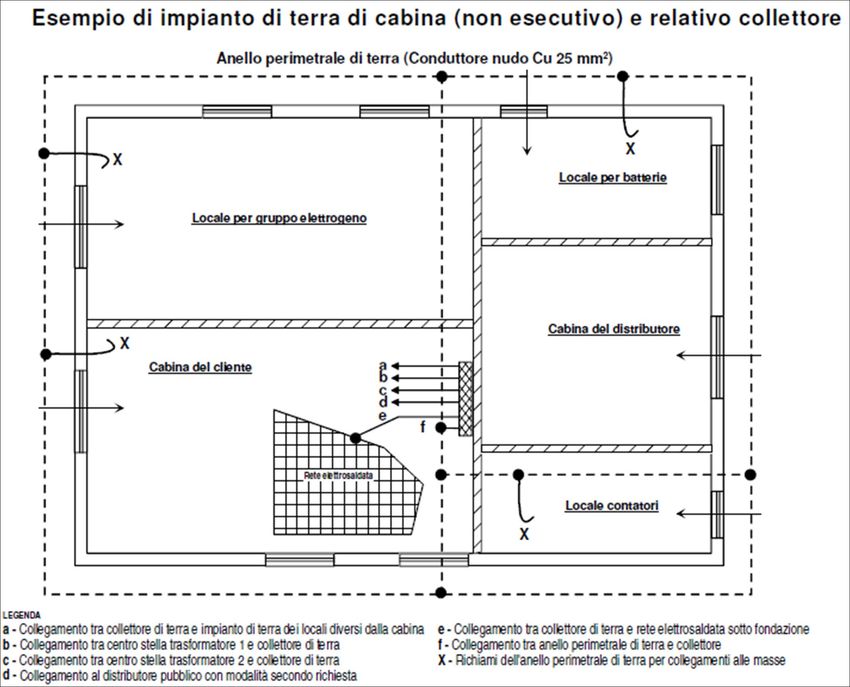
1. Medium voltage/low voltage (MV/LV)
   transformer substations

1.1 Introduction                                                   1.2 Reference standard and
The subject of this Technical Guide is MV/LV substations;
in accordance with the reference standard, the discussion
                                                                       documentation
will be limited to substations with installed power limited to     The general picture providing an overview of the key reference
2000 kVA or two 1000 kVA MV/LV transformers.                       regulations relating to the design and construction of a MV/LV
The purpose of this guide is to give an overview of the            substation is shown in the following figure.
guidelines and requirements specified by current regulations       As you can see, the overview is complex, but on the other
for the design and construction of substations in order            hand the MV/LV electrical substation is the synthesis of
to guide the designer and the user to the correct system           several design activities (electrical, mechanical, construction,
choices.                                                           installation, etc.) and it is therefore also necessary to consider
The document will only touch on a few topics such as the           fire prevention laws on safety and construction materials in
thee sizing of the earthing system and the building aspects,       order to obtain a workmanlike result.
for further details on which you are referred to the specific
regulations.
Lastly, the document does not deal with issues related to
active Users, in other words those that produce alternating
current electricity with parallel operation (even temporary)
with the network.

                                                          Legislation for
                                        System             construction
                                     standards for          products            Fire Prevention
                                      activity and                                 legislation
                                     maintenance

                      Standards
                                                                                                  Legislation for
                     and product
                                                                                                  the prevention
                    guidelines for
                                                                                                  of accidents in
                   switchgear and
                                                                                                  the workplace
                    components

            CEI 0-16                                                                                        EMC legislation

    CEI EN 61936-1                                                                                                  CEI EN 50522

2
A non-exhaustive list is provided below of the main Reference
Standards used in the drawing up of this Technical Guide.
                                                                    1.3 Traditional definitions and
– CEI TS 62271-210: High-voltage switchgear and
  controlgear - Part 210: Seismic qualification for metal
                                                                        types
  enclosed and solid-insulation enclosed switchgear and             An electrical substation is a part of the electrical installation
  controlgear assemblies for rated voltages above 1 kV and          that includes the terminations of the transmission or
  up to and including 52 kV                                         distribution lines and switchgear, and which may also include
– CEI 99-4: Customer/End user guide to creating MV/LV               transformers The substation also typically includes all the
  electrical substations                                            necessary devices for control and protection. Depending on
– CEI EN 61936-1: CEI classification: 99-2, Power                   the function performed, it can be defined as a transforming,
                                                                    conversion, transmission or distribution substation. A MV/
  installations exceeding 1 kV a.c. – Part 1: Common rules
                                                                    LV transformer electrical substation consists, therefore, of the
– CEI EN 50522: CEI classification:99-3, Earthing of electrical
                                                                    set of devices dedicated to the transformation of the voltage
  installations with voltage greater than 1 kV AC
                                                                    supplied by the distribution network at medium voltage (e.g.
– CEI EN 62271-1: High voltage switchgear and controlgear,
                                                                    20 kV), into voltage values suitable for the power supply of the
  Part 1: Common specifications
                                                                    low voltage lines (e.g. 400 V).
– CEI EN 62271-200: AC metal-enclosed switchgear and
  controlgear for rated voltages above 1 kV and up to and
                                                                    Electrical substations can also be divided into public and
  including 52 kV
                                                                    private substations:
– CEI EN 62271-202: High-voltage/low-voltage prefabricated
                                                                    – public substations: these belong to the electricity
  substation
                                                                      distribution company and supply private users in single-
– CEI EN 50532: Compact switchgear assembly for
                                                                      phase or three-phase alternating current (typical voltage
  distribution stations
                                                                      values for the two types of power supply could be 230
– CEI 11 – 17 and variant V1: Systems for generation,
                                                                      V and 400 V). They are in turn divided into urban or rural
  transmission and public distribution of electrical energy.
                                                                      substations, consisting of a single small power transformer.
  Cable line;
                                                                      Urban substations are usually built in brick, whereas rural
– CEI 64-8: User electrical installations with rated voltage not
                                                                      ones are often installed externally directly on the MV pylon.
  greater than 1000 V AC and 1500 V DC;
                                                                    – private substations: these can often be considered as
– Guide CEI 11 - 37: Guide for the implementation of earthing
                                                                      terminal type substations, i.e. substations where the MV
  systems in user energy systems powered at a voltage
                                                                      line ends at the installation point of the substation itself.
  greater than 1 kV.
                                                                      They are owned by the User and can supply both civil users
– CEI 64-12, Guide for the implementation of the earthing
                                                                      (schools, hospitals, etc.) and industrial users with supply
  system in buildings for residential use and in the service
                                                                      from the public MV grid. The user must make available to
  sector
                                                                      the distributing company a special room, accessible to the
– CEI EN 50272-2: Safety requirements for accumulator
                                                                      staff of the company, in which the equipment for which
  batteries and their installations, Part 2: Stationary batteries
                                                                      the distribution company is responsible will be installed.
– DK 5600 ed.IV -March 2004: Criteria for the connection of
                                                                      There can be various design solutions, although in recent
  customers to the MV distribution network
                                                                      times the use of prefabricated substations is increasingly
Please note that the Law no.186 of 1 March 1968 and
                                                                      widespread.
Ministerial Decree no.37 of 22 January 2008, updated by
the Decree of 19 July 2010, assigned a legal role to CEI
standards. Indeed, Article 2 of the Law and Article 6 of the
Decree state that the installations must be constructed in
a workmanlike manner, and that this goal can be achieve
through compliance with CEI standards.

                                                                                                                                    3
2. Design and construction
   specifications of the substation

2.1 Connection of the                                              6. User requirements regarding continuity of the service.
                                                                   7. User requirements regarding slow variations, voltage dips,
    substation                                                        short-circuit power and voltage quality.
                                                                   8. Possibility of developing the network in order to satisfy the
The Standard CEI 0-16 suggests three steps for identifying            requirements in the above points.
the system for the connection.                                     The indicative values of power that can be connected on
                                                                   the different voltage levels of the distribution networks are
Step 1, choosing the voltage level and point of the distribution   specified by the standard in the following table.
network to which the user can be connected depending on
the type, the size and operating requirements of the User
installation and on the requirements and characteristics of the    power MW                          Network voltage level
portion of the distribution network involved.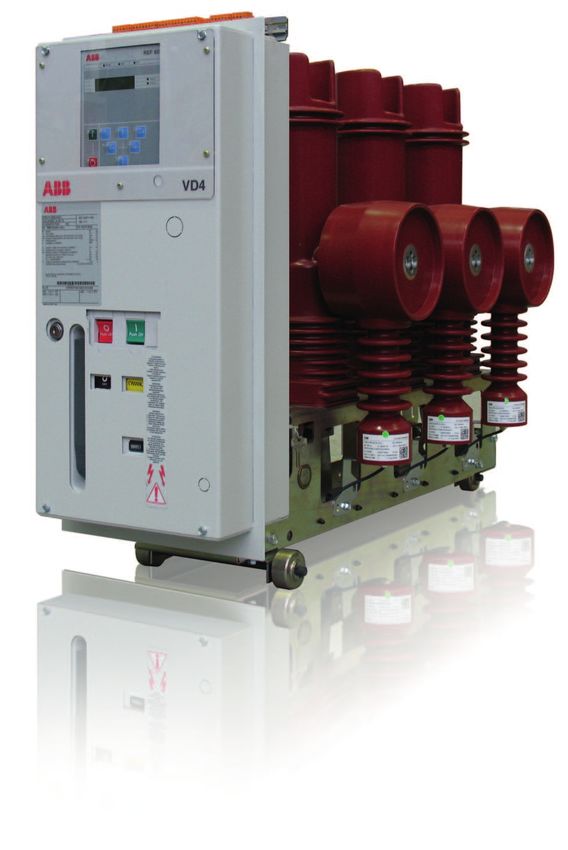
Step 2, choosing the installation insertion scheme (in-out,
antenna, etc.).
                                                                                      2.2 Structure of the substation
To determine the connection scheme the following factors                              These substations are for the most part located in the in the
must be taken into account:                                                           actual premises of the establishment that they supply and
– the size of the installation;                                                       basically consist of three distinct room, of which the first two
– the position of the installation in relation to the network                         are available to the Distributor:
  and the presence, in the area of question, of generating                            – Distributor room (D): where the switching devices of the
  installations, lines and primary and secondary substations;                           Distributor are installed. This room must be large enough
– operation of the network to which the installation is                                 to allow for possible construction of the incoming-outgoing
  connected;                                                                            system that the Distributor is entitled to implement, even at
– possibility to develop the network;                                                   a later stage to satisfy new requirements. The delivery room
– protection and automation devices on the Distributor's                                houses the sampling point that represents the boundary
  network;                                                                              and the connection between the public grid and the user
– User requirements concerning the continuity and quality of                            installation.
  service.                                                                            – metering room (M): where the metering equipment is
                                                                                        located. Both of these rooms must be accessible from a
Step 3, choosing the connection scheme (busbar systems                                  public road, to allow maintenance by authorized personnel
and switching and disconnection parts, in relation to                                   regardless of whether the User is present.
maintenance and the network protection system). Regardless                            – User room (U): intended to contain the MV and LV
of the connection solution chosen for the network system at                             switchgear and protection devices of the User. This room
the user site, the installation will always be as shown in the                          must normally be adjacent to the other two rooms.
following figure.

                              D                                                 M                            U
              SL             SL            SC

                                                                               Wh

                                                                               Pmax                                           Where:
                                                                                                                              D = Distributor room at the user
                                                                                                                                     site.
                                                                               varh
                                                                                                             2                M = metering room,
                                                                                                                              U = User room,
                                                                                                                              SL = cubicle (cell) for line,
                                                                                                                              SC = cubicle (cell) for delivery,
                                                                                                                              C = connection point.
                                                                                                                              1 = metering unit,
                   3                                      C                                                                   2 = General User device,
                                                                                1                                             3 = cubicle present/to be
                                                                                                                                     provided for incoming-
    Line                                                                                                                             outgoing connection.

    Line                                        Connection cable (set up by the User)

Connection diagram between the Distributor's substation at the user site and the User's passive system (CEI 0-16, Figure 7)

                                                                                                                                                                  5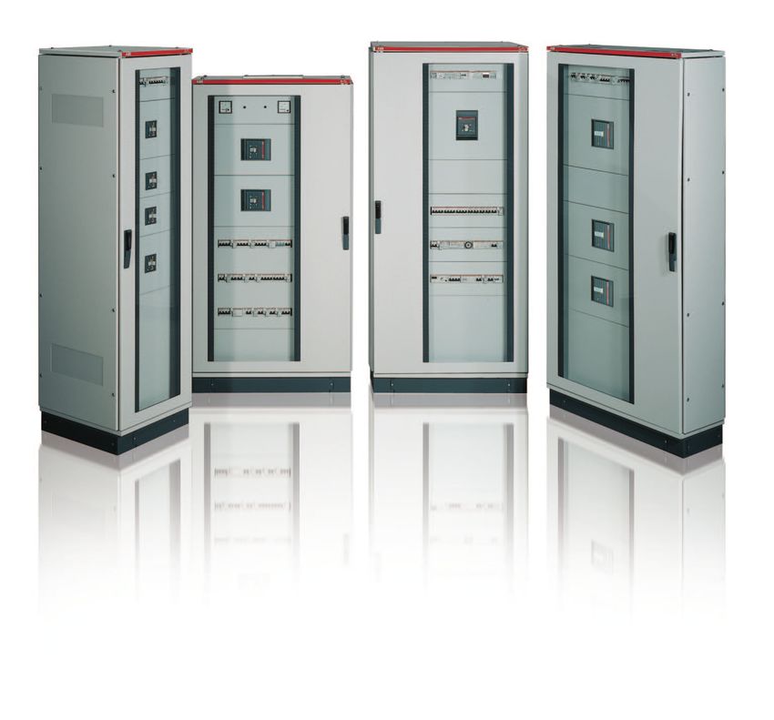
2. Design and construction
specifications of the substation
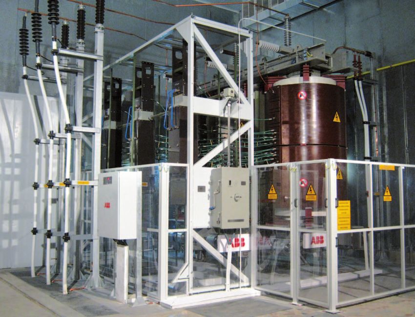
2.3 Construction solutions – Substation built on site or pre-assembled with
prefabricated equipment (internal installation of closed
With regard to building solutions, the Guide CEI 99-4 type CEI EN 61936-1): installation whose electrical
distinguishes between the following cases: components are encased in housing capable of ensuring
– Open substation (internal system of the open type protection against direct contact and which is implemented
according to CEI EN 61936-1): installation in which it using prefabricated devices, such as MV and LV switchgear
not required to use MV components with casing able according to product standard CEI EN 62271-200.
to provide protection against direct contact and which By substation built on site we mean the structure made
therefore needs to be completed on site with the security from concrete or brick or other material suitable for
measures designed to protect persons against such risks accommodating electrical equipment tested directly in situ.
in accordance with CEI EN 61936-1. The installation The typical constructive solution for an internal substation
is implemented directly on the site by connecting the with prefabricated equipment is the following:
components appropriately and it is therefore practically - MV switchgear consisting of a set of functional units
impossible to run tests to verify the level of isolation according to the project;
achieved and the ability to withstand the effects of short- - one or more cells, equipped with walls or dividing panels
circuit currents. The construction solution of a typical and everything necessary for arranging transformers
internal open substation, which is therefore built in a closed housed in prefabricated metal boxes, or else including any
structure sheltered from the elements, generally consist of: necessary protections against direct contacts;
– one or more cells, equipped with walls or dividing panels, - LV switchgear consisting of a set of functional units.
for positioning the MV components;
– one or more cells, equipped with walls or dividing panels
and everything necessary for positioning the transformers;
– protection barriers such as frames, gratings and wire
meshes, fastened rigidly with a minimum degree of
protection IPXXB;
– LV components arranged on open structures or in closed
cabinets.
6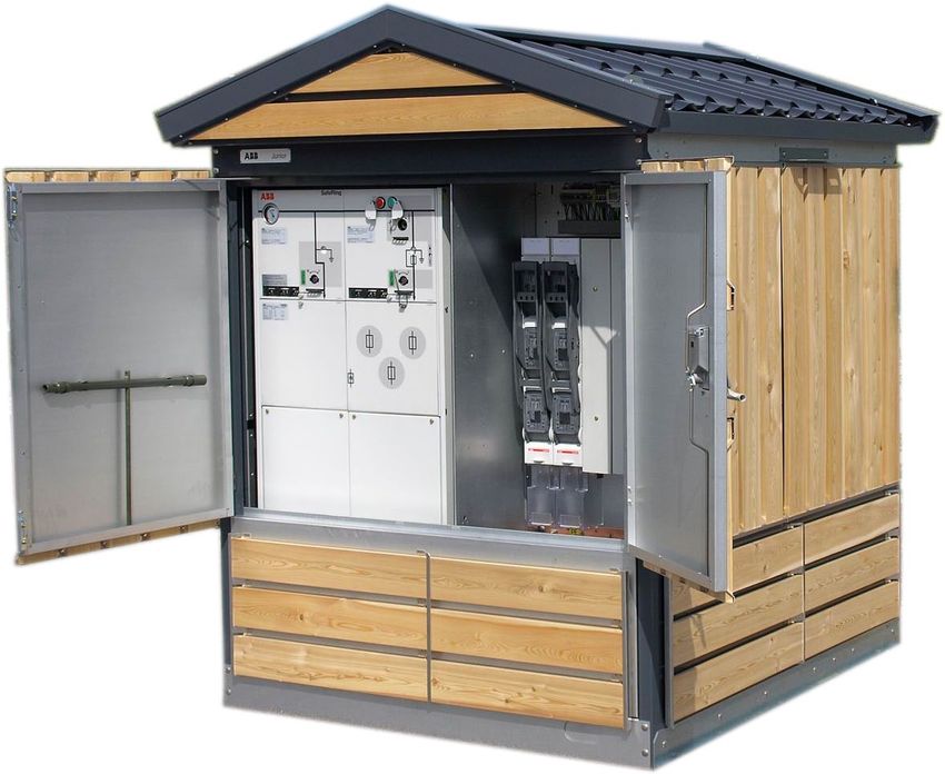
– Prefabricated substation in accordance with standards
  CEI EN 62271-202 and CEI EN 50532: the prefabricated
                                                              2.4 Main requirements
  substation is considered equipment conforming to the        Regarding the location, the substation can be within the
  product standard and that has therefore passed all the      volume of the building to be powered or separate from it. It
  required tests. The product standard, as well as ratings    may also be located on the roof of the building to be served,
  and test procedures, pays particular attention to the       of course, after a careful study of the static and dynamic
  protection of persons, which is guaranteed by the use of    loads to which the roof will be subjected. In any case, the
  components subjected to type tests and by a proper design   location of the substations must be such that it allows
  and construction of the housing. The main components of a   authorized personnel to access it as necessary, to perform
  prefabricated substation, in addition to the casing, are:   service operations and maintenance on the components of
  - power transformers;                                       the substation, even of those of greater size and weight, such
  - medium and low voltage switchgear;                        as transformers.
  - medium and low voltage interconnections;                  In addition, the substation structure must meet the
  - auxiliary switchgear and circuits.                        requirements of the standards (CEI 99-4, Sec. 5 and CEI
                                                              0-16, para. 8.5.9) as regards:
                                                              a) low frequency magnetic fields
                                                              b) access
                                                              c) walls, floors and ceilings, etc. in accordance with Standard
                                                                  CEI 61936-1
                                                              d) ventilation
                                                              e) infiltration of water or flooding
                                                              f) the expected static and dynamic mechanical loads and
                                                                  internal overpressure caused by arcing
                                                              g) lighting
                                                              The substations must be fitted with lockable doors or
                                                              otherwise require the use of tools to open or remove them so
                                                              as to prevent access by unauthorized persons. In particular,
                                                              the room hosting the metering systems must be accessible
                                                              both by the User and by the Distributor.
                                                              The location of the structures must be such that the MV
                                                              lines necessary for connection can be built and maintained
                                                              in compliance with current regulations regarding electrical
                                                              installations and safety as well as electromagnetic pollution.
                                                              Separation, in terms of responsibility for the operation,
                                                              running and maintenance of the various substations, should
                                                              be easily distinguished on the planimetric diagrams.
                                                              Measurement of the energy withdrawn by a User at a
                                                              sampling point must take place close to the MV connection
                                                              using voltage and current transformers that are the
                                                              responsibility of the Distributor. The dimensions of the
                                                              connection room must necessarily allow the in-out insertion
                                                              scheme to be adopted, which might be necessary at a later
                                                              time. As a guideline, the overall surface area occupied by the
                                                              delivery and metering room should be about 16 m2.
                                                              The construction details are to be provided in the connection
                                                              documentation provided by the Distributor; in any case,
                                                              the design of the room for the network system at the user
                                                              installation must comply with the regulations issued by the
                                                              Distributor.

                                                                                                                            7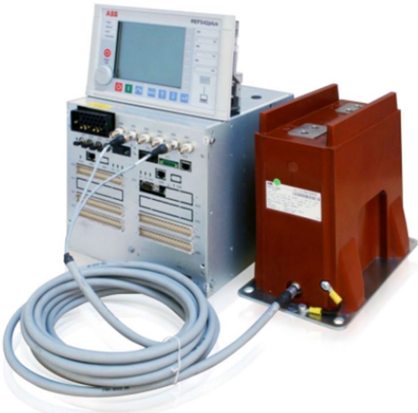
2. Design and construction
   specifications of the substation

Sample solution for substation (non-executive) with equipment against the walls (CEI 99-4, Fig. A.3)

                                                                                                                Room for batteries
                                                    Fume exhaust

                                                                                                  Electrical
                                            Room for generator unit                              switchgear

                                    Switchgear
                                   Generator unit
                                                                  Incom.

                                                                           Gener.

                                                                                     TR2
                                                                                           TR1
                                                                            C.b.

                            LV Switchgear     LV Switchgear
                                                                    MV

                                                                                                        Distributor room (D)

                                               User room (U)

                                                                                                               Metering room (M)
                                                  Transformer 1            Transformer 2

Before positioning equipment inside a substation, you must                          The passages for installation or maintenance located behind
make sure that the correct distances are observed in the                            solid walls (e.g. closed switchgear) should not be less than
service areas, such as hallways, passages, access and                               500 mm.
escape routes.                                                                      In essence, the staff must always have clear and safe access.
In this regard, CEI 99-4 defines that the width of a                                Even overhead, under the ceiling, coverings or housing, with
maneuvering corridor inside a substation must be sufficient to                      the sole exception of the cable conduits, a minimum height of
perform any maneuver or maintenance operation. The width                            2000 mm is required.
of this corridor must be at least 800 mm.                                           As regards the escape routes, for the purposes of standard
In particular, make sure that the doors in the open position                        CEI EN 61936-1, the exits must be set up so that the length
or the mechanical switching devices protruding from the                             of the escape route within the structure does not exceed
switchgear and controlgear do not reduce the width of the                           20 m for voltages up to 52 kV. The recommended length for
corridor to less than 500 mm.                                                       escape routes, however, is no more than 10 m. In addition to
                                                                                    this length it is recommended that the passages should be
                                                                                    accessible from both sides.

8
2.5 Characteristic of the Specifications for seismic action
Since Italy is a country with high seismic exposure, it is
structure important to consider this type of action in the design of the
substation and in the choice of electrical equipment. Once
Structural specifications again it is important to rely on qualified builders who have
As for the construction of the building and its accessories, designed and tested their equipment in accordance with the
you should refer to Italian Ministerial Decree (infrastructure) relevant standards. In fact, the strong vibrations caused by
14.01.2008 as subsequently amended “Approval of new an earthquake have a serious impact on the behavior of the
technical standards for constructions” published in the electrical switchgear.
Official Gazette. no. 29 of 4 February 2008. The decree This is demonstrated by the fact that CEI Guide 99-4 states
defines the principles for the design, construction and testing in note 1 that when technical specification IEC TS 62271-210
of buildings in relation to the requirements of strength and “High-voltage switchgear and controlgear - Part 210: Seismic
stability. Consideration should also be given to Regulation qualification for metal enclosed and solid-insulation enclosed
(EU) 305/2011, which came into force on 1 July 2013 and switchgear and controlgear assemblies for rated voltages
which permanently replaces CPD Directive 89/106/EEC. The above 1 kV and up to and including 52 kV” is published, it
purpose of this Regulation is to regulate the introduction to will be implemented by the CEI regardless of whether it is
the European market of all products (materials, manufactured transposed by CENELEC.
products, systems, etc.) that are designed to become a In the past, the country was classified into zones according to
permanent part of construction works (buildings and civil seismic characteristics; each area was assigned a basic risk
engineering works), which should ensure compliance with at expressed in terms of maximum acceleration on rigid ground
least one of the following requirements, the first six of which (g).
were already specified by the previous Directive CPD 89/106, The current reference source is the web site of the INGV
to which the last one is added: (Istituto Nazionale di Geofisica e Vulcanologia - National
– mechanical strength and stability Institute of Geophysics and Volcanology) http://esse1.mi.ingv.
– safety in the event of fire it/. From this site you can obtain the ag acceleration values
– hygiene, safety and environment for various probabilities of being exceeded in 50 years,
– safety during use corresponding to different return periods.
– protection against noise The entire national territory has been divided up using a
– energy savings calculation grid (steps of 0.05°, equal to approximately 5.5 km
– sustainable use of natural resources for creating the in latitude and longitude) the points of which are identified by
constructions. code numbers (ID). For each of the 16852 points, ordered
The EU Regulation 305 defines, in particular, the loads from west to east and from north to south, the average values
and impacts, nominal and/or characteristic, applicable to (50th percentile) and those corresponding to the 16th and
buildings, and therefore also the housing of a substation, 84th percentile are given.
which must therefore have enough mechanical strength to Using the seismic risk interactive map you can easily ascertain
resist them; these are: the acceleration value ag corresponding to the zone where
– permanent structural and non-structural loads such as the the substation is located and ask the manufacturer of the MV
weights of the materials themselves switchgear to provide a suitable product that matches the
– variable loads including loads related to the intended use of specifications of Technical Specification IEC/TS 62271-210, in
the work (persons, vehicles, etc.). particular as regards the level of severity:
– seismic action – level 1, recommended for peak ground/floor accelerations
– combination of seismic action with the other actions up to 0.5 g;
– actions of the wind – level 2, recommended for peak ground/floor acceleration up
– actions of the snow to 1.0 g.
– actions of the temperature Note that the ag values provided by the site require
– exceptional actions such as fires, explosions, shocks. knowledgeable use and should therefore their use is solely the
responsibility of the user.
92. Design and construction specifications of the substation The seismic hazard map available on the website of the National Institute of Geophysics and Volcanology is shown below. Source: Istituto Nazionale di Geofisica e Vulcanologia (National institute of Geophysics and Volcanology). 10
The functional units of the ABB UniSec switchgear have been                         The form of the spectrum (Required Response Spectra,
tested up to level 2, equivalent to Standard IEEE 693 high                          or RRS) can simulate the various conditions related to the
performance level.                                                                  intensity, depth and distance from the epicenter of the
The RRS corresponding to severity level 2 indicated in IEC/TS                       earthquake, the ground type and the high position of the
62271-210 are provided below.                                                       switchgear located on the upper floors.

                                                                    Severity Level 2 (hor.):

                                    40
                                                                                                             RRS (hor.) ZPA 1g d=2% (level 2)
                                                                                                             RRS (hor.) ZPA 1g d=5% (level 2)
                                    35
                                                                                                             RRS (hor.) ZPA 1g d=10% (level 2)
                                    30
          Horizontal Acceleration

                                    25
                  [m/s2]

                                    20

                                    15

                                    10

                                     5

                                     0
                                         0                                     10                                                 100
                                                                         Frequency [Hz]

                                             Severity Level 2 (horizonthal) – Zero period acceleration (ZPA) = 1 g

                                                                                                                                                 11
2. Design and construction specifications of the substation The figure indicates the positions of the accelerometers during the seismic test. 12
Specifications for fire action                                                    Finally, we come to Standard CEI EN 61936-1 that prescribes
As regards resistance to fire, the standard requires that the                     the requirements that the substation structure must possess
means of classification of fire resistance of construction                        in the event of a fire involving transformers with different
products and elements of construction works must be                               characteristics, namely:
identified in accordance with the Decree of the Ministry of                       – REI 60 for transformers up to 1000 liters of oil type O
Interior of 16/02/2007.                                                           – REI 90 transformers for more than 1000 liters of oil type O
The aforementioned Ministerial Decree provides the following                      – REI 60 for dry transformers in class F0, while non-
explanatory table regarding the classification:                                      combustible walls are enough in the case of dry type
                                                                                     transformers in class F1 (CEI EN 60076-11 Power
Symbols                                                                              transformers Part 11: Dry-type transformers).
R            Bearing            P or       Continuity of current or signaling
             capacity           Ph         capacity
E            Resistance         G          Resistance on soot burning
                                                                                  For transformers with oil content greater than 1000 liters you
I            Insulation         K          Fire protection capacity
                                                                                  also need to refer to the Ministerial Decree of 15 July 2014:
W            Radiation          D          Duration of stability at constant
                                                                                  Approval of the Technical Regulation for Fire Prevention for the
                                           temperature                            Design, Installation and Operation of Fixed Electrical Machines
M            Mechanical         DH         Duration of stability along the        with Presence of Combustible Insulating Fluids in a Quantity
             action                        standard time-temperature curve        Exceeding 1 m3. Official Journal 5 August 2014, no. 180.
C            Automatic          F          Functionality of motorized smoke and
             closing device                heat exhaust systems
S            Smoke              B          Functionality of natural smoke and
                                                                                  Again in the case of substations containing transformers in
             resistance                    heat exhaust systems                   oil, in order not to pollute the environment, the Standard CEI
                                                                                  EN 61936-1 states that measures must be implemented for
                                                                                  the containment of the insulating oil by providing a waterproof
Classifications are typically expressed in minutes, e.g. for
                                                                                  floor with the containment thresholds around the area where
floors and roofs, REI 60 indicates the load-bearing capacity,
                                                                                  the transformer is located or by conveying the leaked fluid
resistance and insulation against fire will be maintained for 60
                                                                                  into a suitable containment area within the building. When
minutes.
                                                                                  defining the containment volume you need to consider the
In particular, as regards activities subject to fire prevention
                                                                                  total volume of the insulating liquid in the transformer and the
control, and in our case substations with fixed electrical
                                                                                  water discharged from the fire fighting system.
machines with presence of combustible insulating liquids in
quantities exceeding 1 m3 and substations inserted in the
volume of the buildings subject to fire prevention control,
the fire resistance of the structures must be certified in
the manner required by Annex II of the Ministerial Decree
07/08/2012 using the forms available from the website www.
vigilfuoco.it.
The following table extracted from Standard IEC EN 60695-1-
40, Fire Hazard Testing, Part 1-40: Guidelines for Assessing
the Fire Hazard of Electrotechnical products - Insulating
Liquids, we can find the classification of insulating liquids                                                                             Threshold
in relation to the point of combustion and the heat of
combustion:

Fire point                                 Net heat of combustion
Class O         ≤    300 °C                Class 1        ≥     42 MJ/kg          The figure shows a section of the transformer room where the
                                                          <     42 MJ/kg          hatched area indicates the containment volume.
Class K         > 300 °C                   Class 2
                                                          ≥     32 MJ/kg          When disposing of the products of combustion in the event
Class L         No measurable              Class 3        <     32 MJ/kg          of a fire the Fire Prevention Regulations must be taken into
                fire point
                                                                                  account.
Example Mineral transformer oil (IEC 60296) has a classification of O1.

                                                                                                                                                 13
2. Design and construction
specifications of the substation
2.6 Thermal sizing and since it can generate oxygen insufficiency (this occurs
when the percentage of oxygen in the air falls below 18%)
ventilation an excessive concentration must be prevented. For this
purpose, in structures located above ground level, natural
While the devices are operating they must not exceed the ventilation is sufficient.
maximum temperature to avoid degrading the insulating In structures below ground level if a harmful concentration is
materials or having to resort to downgrading. possible, forced ventilation must be provided. This also true
In the room where the switchgear and controlgear are located for compartments (e.g. conduits) positioned under switchgear
the following must be provided: in SF6. However, forced ventilation may be omitted when the
– in the lower part, one or more air inlets with their bottom volume of SF6 gas in a compartment of a bigger size than
edge raised from adequately above the floor of the room the switchgear and controlgear, in relation to atmospheric
(approximately 20 cm); pressure, does not exceed 10% of the volume of the
– at the top, flues or windows, preferably open towards to the structure.
fresh air. The entire Annex J of Standard CEI 99-4 is dedicated to the
thermal sizing and ventilation of the structure.
Obviously, the vents can not draw from rooms that are at Speaking of ventilation, Annex B of CEI 99-4 provides a
high temperatures or from places that are classified at risk of summary of the requirements of standard CEI EN 50272-2
explosion according to Standard CEI 31-30 and must in any concerning the ventilation of battery rooms and an indicative
case ensure a degree of protection that will prevent water or example. During charging, the batteries develop hydrogen
snow from penetrating, and animals or objects from getting in and oxygen as a result of the electrolysis process. The
that could cause accidents. ventilation of battery rooms is necessary to keep the hydrogen
Where there is switchgear insulated with SF6, please note that concentration in the air volume in question below the danger
this gas complies with CEI 10-7 and is not toxic; however, of explosion, in other words 4%.
Example views of a substation (non-executive) to highlight the ventilation windows (CEI 99-4, Figure A.5)
Front view
Rear View
142.7 Artificial lighting – floating floor with removable tiles and inspectable space
for cables for which we a height of not less than 0.6 m is
To allow the substation to be operated more easily and safely, recommended. This solution is suitable for cases where the
artificial lighting must guarantee an illuminance level of 200 lx number of incoming and outgoing cables is limited while the
referring, unless otherwise stated, to a uniformity factor of at number of interconnection cables between the switchgear
least 0.7 (UNI EN 12464-1). of the same substation is high
For emergency/security lighting, for example, to identify the – conduits, or a fixed floor and cables contained in conduits
escape routes and the exits of the substation, the illuminance prefabricated or built on site
level must be equal to at least 1 lx that can be obtained using – walkways or equivalent systems (see CEI EN 61936-1); the
autonomous lighting equipment (for example by equipping connections between the various components are mainly
operators with a portable lighting device with one hour implemented by using ceiling cable suspension systems
autonomy). and wall mounted systems made of insulating or metal
material
– The Distributor normally indicates how the holes for
2.8 Electrical cables in the passing of cables are to be created, between the part of
the Distributor's part of the substation structure and the
substation: position, entry customer's receiver part. In any case, all openings to the
points and separation of outside must be made in accordance with the Standards
CEI 11-17 and CEI EN 61936-1 to prevent the entry of
the circuits animals and water and to prevent the spread of any fires
– we also emphasize compliance with Standard CEI EN
As regards the cables, in substations we can have the 61936-1 and the product standard for the cables for the
following situations: sizing and positioning of the conduits and protective tubes
– accessible sub-panel compartment, or a walkable basement embedded in the masonry that must ensure compliance with
under the supporting plane of the switchgear, for which a net the curvature radii of the cables and allow free expansion
height of not less than 1.7 m is recommended. This solution – the armor or metal screen of the cables can be considered
is suitable for cases where the cables entering and leaving as metallic segregation. Therefore the MV cables that are
the substation are many and buried laid on walkways, conduits, piping, etc., can coexist with
low voltage cables
Example of an electrical substation (non-executive) highlighting the ducts in the floor and the conduits (CEI 99-4, Fig. A.2)
Key
Traps with
dimensions
Room for batteries according to requirements
Room for generator unit Conduits and traps with a
depth of about 50 cm
Conduit Note: the possible
insulating liquid collection
sumps have not been
No. 1 tube indicated
No. 2 tubes ø 160 mm
Conduit Unified door
ø 160 mm
Output by the distributor
cables Distributor room (D)
Conduit Conduit
of the Tubes for MV and LV
customer of the distributer
No. 3 tubes
ø 160 mm
Conduit for the distributor
User room (U) No. 2 tubes for
Metering room (M) measurement
ø 100 mm
152. Design and construction
specifications of the substation
2.9 Earthing systems The figure below, taken from CEI 99-4, illustrates - merely by
way of example - some characteristics of the earthing system
Particular attention should be paid to the design and in order to draw attention to the elements that make up the
construction of the substation earthing system. The earthing earthing system.
system is not addressed directly by CEI 99-4 that refers for
such details to CEI EN 50522 and for MV systems and to CEI
64-8 only for the relevant LV systems.
Example of substation earthing system (non-executive) and corresponding collector (CEI 99-4, Fig. A.4)
Perimeter earthing ring (bare Cu conductor 2 mm2)
Room for batteries
Room for generator unit
Distributor room
User room
Electro-welded mesh
Meter room
Key
a - Connection between earthing collector and earthing system of structures other than the substation
b - Connection between transformer 1 star centre and earthing collector
c - Connection between transformer 2 star centre and earthing collector
d - Connection to the public distributor in the manner requested
e - Connection between earthing collector and electro-welded mesh under the foundation
f - Connection between the peripheral earthing ring and collector
x - Reinforcement bars of the perimeter earthing ring for connections to the conductive parts
16We will look at the main requirements of the earthing system Elements of the earth plate
for the three types of substations. – The earth plate can be implemented as a ring with copper
Isolated substation (separated from the building) wire or a steel bar according to Standard CEI EN 50522
– If necessary, insert a perimeter ring earth plate in the and CEI Guide 11-37.
foundation excavation, consisting of a conductor buried – If necessary, the ring may be supplemented with outreaches
directly in virgin soil. or with a second outer ring at a greater depth, possibly
– All the reinforcement steel elements of the foundation can supplemented, for example, with copper-plated steel pegs
be used as an earthing rod. 1.50 m in length complete with a collar for fastening the
– Given that the lateral structural elements of the building are copper rope.
connected together for reasons of staticity, if necessary – Due the type and use of current elements, please refer to
they should be connected to the underfloor electrically the Guide CEI 64-12 and CEI 11-37.
welded mesh to obtain better equalization. – All the necessary measures must be taken to limit
– All the elements that contribute to the formation of the earth the effects of corrosion, with particular attention to
plate must be connected (individually or in groups) to the combinations of different metals (see UNI standards or the
collector of the substation. Guides CEI 11-37 and CEI 64-12 within the relevant scope).
– The filling soil around the earth plate must be of vegetation
Substation included within the volume of the building type and must not contain any waste material.
– The earth plate will be part of the general earth plate of
the building (considered as meshed or a ring or equivalent) Earthing terminal
and will consist of current elements, using the iron bars of – The earth collector (in the form of not necessarily just one
the foundations, possibly supplemented by an intentional drawbar, or a ring) must constitute the point of connection
earthing rod. between the elements of the substation earth plate, the
– All the elements that contribute to the formation of the earth plate of the building where the substation is inserted
earth plate are connected to the main earth collector of the (if required), the MV earth conductors, the LV protective
building, which is not necessarily located in the substation conductors LV and the equipotential conductors. The
structure. horizontal ducts for implementing these connections are
– The collector of the substation is in any case connected to preferably arranged in the floor of the substation.
the main collector. – The studs of reinforcing rods provided as connection points
– In particular, the substation and in its immediate vicinity, must be left free from the pouring of the floor.
measures must be taken to achieve equalization of the – To facilitate the maintenance and checking operations the
potential. In addition, the measures to limit the potentials individual conductors arriving at the collector should be
due to earth faults must be evaluated. signposted.
– The protective, equipotential and earthing conductors, if not
Substation in traditional masonry or prefabricated on the roof exposed, must have a yellow/green sheath.
of a building – The sizing for the sections of the collector and of all the
– The earth plate will be part of the main earth plate of the protective conductors is performed by the designer,
building, and must consist of current elements; in particular, according to the MV and LV earth fault current.
for equalization of potential it is recommended that the – The equipotential conductors for the MV installation, if
reinforcing bars of the pillars and the floor slab of the roof made of copper, must have a minimum cross-section of
should be connected. 16 mm2, (see CEI EN 50522). For LV installations, the main
– The collector of the substation will be connected to the equipotential conductors, if made of copper, must have a
structure of the building directly on the floor where the minimum cross section of 6 mm2 (see Standard CEI 64-8
substation will be positioned. for the relevant installations).
172. Design and construction
specifications of the substation
2.10 Earthing devices required
by the connection
To carry out work with the equipment de-energized,
Standards CEI EN 50110-1 and CEI 11-27 establish that after
identifying the corresponding electrical systems, the following
five essential requirements must be observed in the order
specified:
1) isolate the part of the system involved in the work;
2) take measures against untimely closing the of the
disconnector device;
3) make sure that the system is de-energized;
4) earth and short-circuit the isolated parts;
5) ensure protection against any adjacent live parts.
Regarding point 4), for the construction of the connection,
reference must be made to CEI 0-16, para. 8.2.1 where it
stresses that earthing and short-circuiting of the HV system
(voltage greater than 1 kV) can be implemented in two ways:
– by applying movable devices;
– using, where available, the devices intended for earthing
and short-circuiting the relevant part of the installation.
The User can therefore adopt one of the following system
solutions: 2. Provide an earthing switch immediately downstream of
1. Do not use any earthing switch immediately downstream of the terminals of the network connection cable (in the
the terminals of the network connection cable (in the User User room, network side); in this case the Distributor's
room, network side); in this case the earthing required personnel must deliver a key - that cannot be copied for
by standard CEI 11-27 must be achieved using mobile the User - that is freed once the earthing switch of the
earthing devices made according to Standard CEI EN Distributor's delivery cubicle (cell) has been closed and
61230: Live works - Portable devices for earthing or for which allows the User's first earthing switch to be closed.
earthing and short-circuiting. An appropriate warning must be affixed on this earthing
In particular, the User must also make sure that there is no switch that says "SWITCH TO BE OPERATED ONLY
voltage on the cable in question, earth it and short-circuit it AFTER INTERVENTION BY THE DISTRIBUTOR".
using the aforementioned earthing devices. An appropriate Prior to connection, the Distributor must be informed of
notice must be be affixed to the panel the removal of which which solution was chosen. Once the connection exists,
allows access to the terminals of the cable saying “COVER/ the User cannot change the solution unless there is prior
DOOR REMOVABLE ONLY AFTER ENERGY NETWORK written consent from the Distributor.
ACTION”.
18Two examples of UniSec JTI switchgear are shown below, 2.11 Rating plates, warnings
the first with a keyed earthing switch on the Distributor side
that is the responsibility of the Distributor, and the second and diagrams
with provision for earthing via an insulating rod.
Signs must be installed in the MV/LV substation (prohibition,
warning and alert) created (pictograms and any tests)
according to the provisions of Legislative Decree 81/2008, as
amended, Annex XXV and UNI EN ISO 7010:2012.
-QCE -PFV2 The signs must be made of materials as far as possible
resistant to impacts, weather and damage caused by
-BAD
environmental factors.
Some examples of signs that can be used in an electrical
substation are shown later.
-QAB The Standard provides examples for correct positioning of
notices, rating plates and signs:
-BCS
3 -BCR
– Outside each access door and on every side of any fences:
- “no entry for unauthorized persons”;
- “dangerous voltage”;
- “possible identification of the electrical substation”;
5 6 1 2
– outside the entrance door to the structure, in addition to the
-QBS previous three:
- “do not use water to extinguish fires”;
-PFV1 -QCE1
- “voltage ... kV”;
-BAD – inside the substation:
- “Instructions for emergency aid to be provided to those
injured by electricity” with the sections for the telephone
-BCN
numbers to be contacted case of necessity (the nearest
doctors, hospitals, ambulances, etc.) filled in;
- wiring diagram, which must also indicate, if relevant, also
the color coding used for the various voltages;
– near MV switchgear,
- “voltage … kV”;
-QCE -PFV2
– available to the maintenance personnel,
-BAD - “do not perform switching operations”;
– on any emergency exits:
- the appropriate sign.
-QAB
-BCS
3
-BCR
5 6 1 2
-QBS
-PFV1
-BAD
-BCN
192. Design and construction
specifications of the substation
It is also necessary to indicate any autonomous energy Warning sign with explicit reference
sources near the circuit disconnection device, the presence to the deactivation of the electrical
of accumulator batteries or capacitors on the doors of system before starting work on it
the corresponding cells and lastly, for complex electric
substations, a single line diagram should be displayed.
Combined sign with prohibitions
and warning that can be
supplemented by explicit wording
under one or more of the
Do not alter the state of the circuit-breaker combined elements
Combined sign with prohibition
Sign forbidding access to unauthorized and warning and with a clear
persons indication of the prohibitions or
obligations
Do not extinguish with water
Sign for identification of the circuits
with different colors for the different
Sign warning of the danger of hazardous voltage levels and for the earthing
electrical voltage conductors
Sign for identification of the voltage of
an electrical substation (switchgear)
Sign warning of the hazard of flammable
material or high temperature
Sign for identification the accumulator
battery room
Sign warning of danger due to an
autonomous energy source
The sign for first emergency first aid is shown below; the
standard recommends filling in the necessary data at the
bottom of the sign to ensure the prompt arrival of help.
Note that the standardized pictograms can be combined
and supplemented by explicit wording to make them more
complete and understandable.
Fonte: Norme
Source: UNI EN
UNI
ISO
EN7010
ISO standards.
7010.
20ACT IMMEDIATELY - DELAYING IS FATAL...
EMERGENCY FIRST AID TO BE GIVEN
TO THOSE SUFFERING ELECTRIC SHOCKS
IMMEDIATE ACTION
It is critical when the shock affects breathing and cardiac activity; if the victim is not given aid within 3 or 4 minutes he/she can suffer
irreparable consequences. Ensure first of all that the victim is out of contact with live parts and then immediately start giving artificial
respiration. DO NOT DELAY AID, NOT EVEN TO CALL THE DOCTOR, unless there are at least two aid givers, or if the sole aid giver can
call the attention of others without abandoning the victim.
DO NOT TOUCH
the victim, if you are not sure that he/she is no longer in contact with, or immediately adjacent to live parts. If this not so, disconnect the
power. If the circuit cannot be promptly disconnected, insulation your person by means of insulating gloves,
dry clothes, by standing on dry wooden planks etc. and remove the victim, preferably grabbing him/her by his/her clothes if they are dry.
Alternatively, with a single swift and decisive movement, distance the live part from the victim using insulating rods, pieces of dry wood or
other objects made of insulating material. Do not touch any other objects yourself, especially if they are metal. IF THE ORONASAL MASK
IS NOT AVAILABLE, THE MOUTH TO MOUTH OR MOUTH TO NOSE TECHNIQUE MAY BE USED, POSSIBLY INTERPOSITION PLACING
A HANDKERCHIEF OR GAUZE BETWEEN.
ARTIFICIAL RESPIRATION
with an oronasal mask:
1. Lay the victim on his/her back and position yourself by the side of his/her head. 2. Equip yourself with an appropriate oronasal mask and
position the valve unit correctly in the neck of the mask (see fig. A). 3. Tilt the victim's head back slightly (to open the air passage) placing
one hand behind his/her head while the other acts as a lever on the forehead (see fig. B). 4. Apply the mask, covering the nose and mouth
of the victim, making sure that it stays in the position shown in Fig. B (see fig. C). 5. Give two slow, deep breaths and observe the rising
of the victim's chest. When the chest returns to its natural position, perform a regular cycle of 12-15 insufflations per minute (see fig. D).
A B C D
IMPORTANT: if the person vomits, remove the mask, turn the head to one side and clean the mouth. Before reusing the mask, blow into
the mask to clean it.
CARDIAC MASSAGE
If not only the breathing stops but there is no heartbeat (to look for this sign, using two fingers press the victim's
neck to either side of the Adam's apple), you must perform an external heart massage by pressing rhythmically
on the chest. To do this: 1. Apply both hands superimposed with the palms facing down on the lower part of
the sternum (see the figure at the side). 2. Apply rhythmic vertical pressure actions using your bodyweight and
taking your hands away from the thorax each time to allow it to expand by elasticity. 3. Continue at a rate of
50-60 pressure actions per minute. Cardiac massage must always be preceded by artificial respiration with oral
insufflation. Therefore, while the first aid giver is giving artificial respiration using the oronasal mask, a second will
simultaneously perform CPR. If the aid giver is alone, he/she should behave as follows: start with 5 heart mas-
sage - perform oral insufflation - continue with another 5 massages - perform an insufflation, and so on. Suspend
insufflation actions only when the victim has resumed breathing on his/her own and the pupils start to shrink again: however, check for
some time to make sure that spontaneous breathing is maintained. If this is not the case, continue also during transport to the hospital
and until specialized health personnel can take over.
After recovery, the victim must not be removed until he/she can breathe normally without assistance. He/she should be examined by a
doctor before being allowed to walk. He/she must not be given any stimulant, unless directed by the doctor. Remember also that TIMELI-
NESS IS CRITICAL.
IN THE PRESENCE OF BURNS
1. First of all, start artificial respiration and possibly cardiac massage if the victim is not breathing and has no cardiac activity. 2. Do not
remove burned clothes and do not break any blisters. 3. Do not apply lotions or ointments. 4. Cover the burn with sterile, dry gauze. Also
treat any burns (checking to see if there are any) at the exit points of the current. 5. If the victim has lost consciousness and is able to
swallow, you can give him/her 300 g. water (a bowl) by mouth in which the baking soda and salt contained in the bags provided has been
dissolved. If the victim vomits stop administering the liquid immediately. 6. Transfer the victim to hospital without delay.
NEAREST DOCTORS ................................................... ............................... tel. . . . . . . . . . . . . . . . . . . . . . . . . . . . . . . . . . . . . . . . . . . . . .
.......................................................... ................................................... tel. . . . . . . . . . . . . . . . . . . . . . . . . . . . . . . . . . . . . . . . . . . . . .
NEAREST HOSPITAL ................................................... ................................ tel. . . . . . . . . . . . . . . . . . . . . . . . . . . . . . . . . . . . . . . . . . . . . . .
NEAREST AMBULANCE .................................................... ........................... tel. . . . . . . . . . . . . . . . . . . . . . . . . . . . . . . . . . . . . . . . . . . . . . .
MAKE SURE, HOWEVER THAT THE VICTIM
IS NOT STILL TOUCHING ANY LIVE PARTS
Source: UNI EN ISO 7010 standards.
213. Schematic diagrams for the connection
The schematic diagrams regarding insertion of the User's Existing Existing
installation on the Distributor's network for connection secondary secondary
substation substation
systems are shown in the following figures:
A
Existing Existing
secondary secondary
substation substation
D
D
M
M
U
U
Scheme A: Insertion in-and-out mode for connection in the Scheme C: Insertion in antenna mode with actuating
vicinity of an existing line, so as to generate only two line means (optionally in an additional substation A) along an
sections belonging to two distinct secondary substations. existing line. From the actuating means, there must be a line
Under this scheme, the User can be powered again providing dedicated to powering a user. The room possibly dedicated
better continuity of service. to the actuating means must be able to accommodate the
equipment for possible future adoption of in-out insertion.
Existing
primary Existing Existing
substation secondary secondary
D M U substation substation
D
Scheme B1: Insertion in antenna mode from a HV/MV station;
in this case, it involves the construction of a line powered M
directly from a primary HV/MV substation. This type of U
insertion can be adopted when insertion along an existing line
is not technically possible. In any case, the room dedicated
to the network system at the user site must be able to Scheme E: Inserting a section of line with a rigid T shunt on
accommodate the equipment for possible future adoption of an existing MV line only with the circuit-breaker at the network
in-out insertion. connection system. This scheme is the simplest and least
expensive, but reduces the reliability of the networks; it also
provides inferior continuity of service. This connection is to be
Existing Existing Existing
understood as exceptional.
secondary secondary secondary
substation substation substation
In conclusion, of the connection solution chosen for the
network system at the user site, the installation will always be
D
as shown in the figure on page 5. Starting from the MV cable
M downstream of the connection point, the figure indicates
the layout of a passive User's system for connection. With
U
reference to the above figure, the Distributor's substation at
the user site is the substation created to connect the User's
system.
Scheme B2: Insertion in antenna mode from a HV/MV
substation for connection via a line section connected to the
MV busbars of an existing distribution substation. The room
dedicated to the network system at the user site must be able
to accommodate the equipment for possible future adoption
of in-out insertion.
224. Sizing and choice of equipment
and components
The choice of the wiring diagram of the substation, and
therefore of the related equipment, depends on several
4.1 Disconnectors,
factors such as:
– the number of power lines
switch-disconnectors,
– the number of transformers multifunction devices
– the requirements of the service, etc.
While it is true that the equipment and components of MV systems must include an isolating device upstream of
the substations must be chosen based on the rated each switch disconnector that does not comply with the
characteristics and environmental conditions of the installation standards for disconnectors, for example, a non-withdrawable
location, it is also important, on the basis of what we saw in circuit breaker, and also on the power lines or with possible
the previous chapters, to adopt the necessary precautions, return power supply.
during the substation design phase, so that the operating MV fuses must, in particular, be associated to a switching an
temperatures do not exceed the maximum values allowed by disconnection device that allows them to be replaced safely,
the product standards for the equipment, so as not impair such as a switch-disconnector.
their electrical lifetime and safety. Conversely, prefabricated withdrawable circuit-breakers with
With particular reference to the Standard CEI 0-16, the metal enclosures addressed by the CEI EN 62271-200 also
general device (or DG) and the protection system associated perform the disconnection function.
with the General Device (or General Protection System, Since the disconnectors are not equipped with closing and
abbreviated as SPG below) are essential elements for interruption power, they must be operated in the absence
connection of the Distributor's network. of current and are typically interlocked with the associated
The SPG consists of: switching equipment so as to prevent them from opening or
– current, phase and earthing transformers/transducers closing under load.
(and possibly voltage transformers/transducers) with the In addition, each disconnection device should be
associated connections to the protection relay associated to an earthing switch interlocked with its open or
– protection relay with its power supply disconnected position.
– opening circuits of the circuit-breaker. For these reasons it is often preferable to have a multifunction
device; these devices, since they are coordinated, in fact
The main technical characteristics and the choice of these allow all the problems related to interlocks to be resolved with
devices are described below. factory-tested mechanical solutions.
234. Sizing and choice of equipment
and components
There are basically two types of multifunction devices:
– line switch-disconnector/earthing switch
– circuit-breaker/feeder disconnector/earthing switch
The ABB GSEC switch-disconnector/earthing switch is based
precisely on this design philosophy. The enclosure consists
two half-shells; the upper one in insulating epoxy resin
makes it possible to minimize the distances to the walls of
the switchgear, and therefore to achieve particularly compact
solutions. The lower half-shell, on the other hand, is made of
stainless steel and allows the metallic segregation between
the busbar compartment and the compartment adjacent to
the switchgear, allowing the earthing of the two compartments
and therefore allowing personnel to operate safely. With this
solution it is possible to design electrical switchgear classified
as PM (Metal Partition).
In accordance with Standard CEI EN 62271-1, the device is
classified as a “sealed pressure system” since no interventions
related to the gas will be required during its operational life, in
this case 30 years. In addition, the high number of mechanical 5
operations (class M2=5000 operations with a single spring
1
operating mechanism and class M1=1000 operations with 6
a double spring mechanism) and electrical operations (class
E3 on line contacts with 5 closures on short-circuit currents 7
and 100 interruptions on the rated current) help to make it a 2
virtually maintenance-free device. Its compactness is further
8
improved also by the integration of the capacitive sockets 3
and cable connections directly on the lower insulators. The
switchgear can then mount a Voltage Presence Indicating 9
4
System (VPIS) system, which signals the presence of voltage
on the cables connected to the switchgear in accordance
with the Standard IEC 61958. Upon completion of the safety
measures we find a mechanical indication of the position of
the switchgear, a signal connected directly to the operating
shaft of the switchgear (as per Annex A of IEC 62271-102).
1 Opening and closing push-buttons 5. Top insulators
2. Connection for the line operating 6. Enclosure (power part)
lever 7. Housing of the operating
3. Connection for the earth operating mechanism
lever 8. Bottom insulators
4. Voltage signalling lamps 9. Mimic diagram
(if applicable)
Line Open Earth
24You can also read


