THE CRUISE INDUSTRY AND THE POLAR CODE - UIT.NO
←
→
Page content transcription
If your browser does not render page correctly, please read the page content below
Faculty of Science and Technology
Department of Technology and Safety

The Cruise Industry and the Polar Code
Implementing the Polar Code

—

Bendik Skoglund Kristiansen
Master’s thesis in Technology and Safety in the High North TEK-3901 - June 2019
Acknowledgements
This thesis concludes my master’s degree in Technology and Safety in the High North with
specialization in nautical science at the Faculty of Science and Technology, UiT – The Arctic
University of Norway.

First and foremost, I would like to thank my two supervisors; Andreas Kjøl at the Norwegian
Coastal Administration who introduced the idea for the thesis and has provided valuable
inputs regularly along the way, and professor Ove Tobias Gudmestad who did not hesitate to
be my main supervisor when called upon and who have provided excellent guidance and
feedback these last few months.

I would also like to thank everyone who has taken the time to reply to the questionnaire. The
thesis would not be same without these replies.

Finally, I want to thank my little family, Lena and Henrik, for giving me the time I needed to
complete this.

Bendik Skoglund Kristiansen

Tromsø, June 2019

                                               i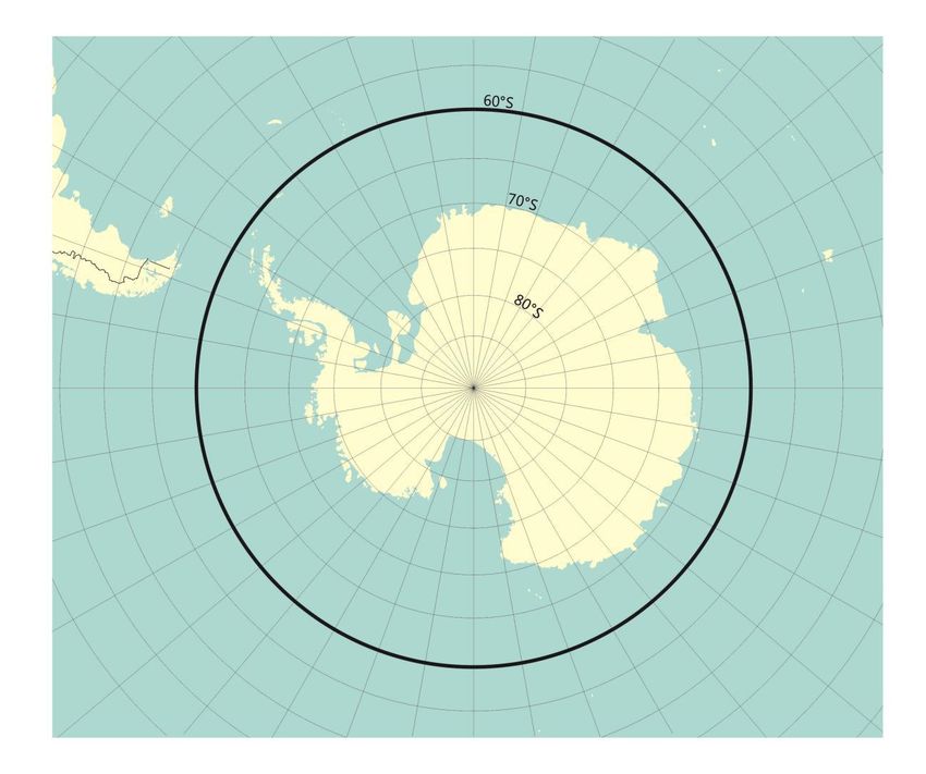
ii
Abstract
The mandatory Polar Code is now set into force with strengthened requirements for vessels
operating in polar waters. The polar cruise shipping segment is growing as the maritime
activity in polar waters is increasing. There are many challenges, and the polar environment
adds an increased risk level. The preventive actions towards mitigating risks are more
important due to the harsh environment, long distances and limited options for assistant
rescue.

Most accidents and incidents have pre-occurring causes which are not captured until an
unwanted event occurs, or not at all if the unwanted event is minor or less severe. A proper
reporting regime is essential to identify these causes, and this is done through safety
management with all its implications, as well as encouraging a healthy safety culture.

Relevant theory is reviewed, and terms and maritime safety challenges are explained to
provide the basis for the discussion in this thesis. Further basis is provided through a survey
directed towards polar cruise operators and a root cause analysis of a polar cruise vessel
grounding in the Canadian Arctic utilizing reliability engineering methods.

Related to the work with the thesis, I participated in the Fourth Joint Arctic SAR TTX in
Reykjavik this April. Highlights from the event are included in Appendix C and provide
actualization of the research theme: How the polar cruise shipping segment is implementing
the Polar Code.

The results of the survey and the root cause analysis are discussed related to the maritime
safety challenges, and the thesis aims to provide knowledge about the implementation of the
Polar Code in the polar cruise shipping segment, and to identify challenges related to this
process.

Keywords: Polar Code, Root Cause Analysis, Polar Cruise Shipping Segment, Maritime
Safety Challenges, Hybrid Model, Safety Management, Arctic, Cruise, Case Study

                                               iii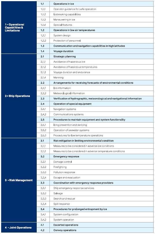
iv
Abbreviations
ACGF      Arctic Coast Guard Forum
AECO      Association of Arctic Expedition Cruise Operators
AHP       Analytical Hierarchy Process
AIRSS     Arctic Ice Regime Shipping System
ARCSAR    Arctic and North-Atlantic Security and Emergency Preparedness Network
ARIF      Arctic Risk Influencing Factors
BRM       Bridge Resource Management
COLREGs   Convention on the International Regulations for Preventing Collisions at Sea
CCGS      Canadian Coast Guard Ship
ECS       Electronic Chart System
ECDIS     Electronic Chart Display and Information System
EGC       Enhanced Group Call
EPPR      Emergency Prevention, Preparedness and Response
FLS       Forward Looking Sonar
FMECA     Failure Mode, Effect and Criticality Analysis
FSA       Formal Safety Assessment
FTA       Fault Tree Analysis
GMDSS     Global Maritime Distress and Safety System
GNSS      Global Navigation Satellite System
GPS       Global Positioning System (USA)
HIFR      Helicopter In-Flight Refuelling
HSEQ      Health, Safety, Environment & Quality
IAATO     International Association of Antarctica Tour Operators
IBNS      Integrated Bridge Navigation System
ICG       Icelandic Coast Guard
IHO       International Hydrographic Organization
ILLC      International Convention on Load Lines
IMCS      Integrated Machinery Control System
IMO       International Maritime Organization
ISM       International Safety Management
JRCC      Joint Rescue Coordination Centre
                                        v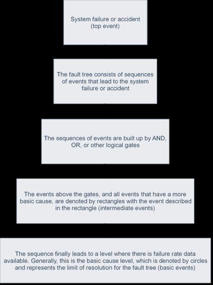
LSA         Life-Saving Appliances
MCTS        Maritime Communication Traffic Service
MARPOL      International Convention for the Prevention of Pollution from Ships
MSC         Maritime Safety Committee
NAVTEX      Navigational Telex
NAVWARN Navigational Warning
NCA         Norwegian Coastal Administration
NMA         Norwegian Maritime Authority
NORDREG Canadian Arctic Marine Traffic System
NOTSHIP     Notice to Shipping (Former Canadian NAVWARN)
NSRA        Northern Sea Route Administration
POLARIS     Polar Operational Limit Assessment Risk Indexing System
PSC         Polar Ship Certificate
PWOM        Polar Water Operations Manual
RBD         Reliability Block Diagram
RIO         Risk Index Outcome
RPN         Risk Priority Number
SAR         Search and Rescue
SARC        Arctic Maritime Safety Cooperation
SAREX       Search and Rescue Exercise
SMS         Safety Management System
SOLAS       International Convention for the Safety of Life at Sea
SOP         Standard Operating Procedure
STCW        International Convention on Standards of Training, Certification and
            Watchkeeping for Seafarers
TSB         Transportation Safety Board of Canada
TTX         Table Top Exercise
VTS         Vessel Traffic Service

                                           vi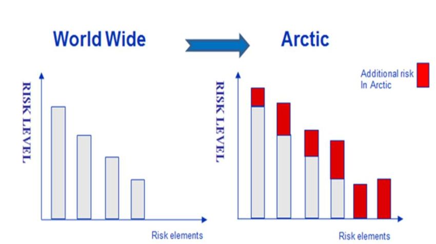
Definitions
The following definitions are used in this thesis

AIRSS                 Canadian regulatory standard intended to minimize the risk of pollution
                      in Arctic waters due to damage of vessels by ice; to emphasize the
                      responsibility of the shipowner and master for safety; and to provide a
                      flexible framework for decision-making.

Contributing          Failures related to regulations, organization, procedures or design.
Factors

Basic/Advanced    Requirement in the Polar Code. Masters, chief mates and officers in
Polar Code Course charge of a navigational watch on board ships operating in polar waters
                  shall have completed training to attain the abilities that are appropriate
                  to the capacity to be filled, and duties and responsibilities to be taken
                  up.

FMECA                 A straight forward step-by-step technique to systematically determining
                      the ways in which a failure can occur, and the effects that each failure
                      can have on overall functionality of a system. (Labib and Read, 2015)

GNSS                  A satellite navigation system with global coverage. The United States’
                      GPS and Russia’s GLONASS are fully operational GNSSs, while the
                      EU’s GALILEO and China’s BDS are expected to be fully operational
                      by the early 2020s.

Hazards               Possible events and conditions that may result in severity, i.e. cause
                      significant harm. (Kristiansen, 2005)

Human Error           An incorrect decision, an improperly performed action or an improper
                      lack of action. (Rothblum et.al, 2002)

Ice Regime            A description of an area with a relatively consistent distribution of any
                      mix of ice types, including open water. (IMO)

ISM Code              The objective of the ISM Code is to ensure safety at sea, prevention of
                      human injury or loss of life, and avoidance of damage to the
                      environment, in particular the marine environment, and to property.
                      (IMO)

LSA Code              The purpose of the LSA Code is to provide international standards for
                      life-saving appliances required by the International Convention for the
                      Safety of Life at Sea (SOLAS). Examples of life-saving appliances are
                      lifeboats, life-rafts, lifebuoys, lifejackets, immersion suits, thermal
                      protective aids and so on. (IMO)

                                               vii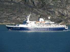
NAVWARN           Navigational information concerning navigational safety. Can be
                  obtained through numerous methods including Inmarsat-C, SafetyNet,
                  Navigational Area (NAVAREA) broadcasts, HF broadcasts, the
                  relevant authority website and by contacting maritime communication
                  traffic services.

NSRA              Russian federal state institution aimed to ensure safe navigation and
                  protection of marine environment from the pollution in the water area
                  of the Northern sea route.

NORDREG           Canadian Arctic marine traffic system created pursuant to the Northern
                  Canada Vessel Traffic Services Zone Regulations. The system is
                  designed to ensure that the most effective services are available to
                  accommodate current and future levels of marine traffic.

Polar Code        The goal of the Polar Code is to provide for safe ship operation and the
                  protection of the polar environment by addressing risks present in polar
                  waters and not adequately mitigated by other instruments of the
                  Organization. (IMO)

POLARIS           A decision support system that can be used for voyage planning and on
                  the ship’s bridge. It uses the ship’s actual ice class and the actual ice
                  conditions encountered to determine a risk index outcome (RIO) –
                  effectively, a way of assigning a level of risk to ice operations for ships
                  with certain ice classes. (Lloyd’s)

Reliability       The ability of a system or component to perform certain defined
                  functions. (Kristiansen, 2005)

Risk              An evaluation of hazards in terms of severity and probability.
                  (Kristiansen, 2005)

Root Causes       Pre-occurring causes which contribute to an event.

Safety            The degree of freedom from danger and harm. Safety is achieved by
                  doing things right the first time and every time. (Kristiansen, 2005)

Safety            Keeping an operation safe through systematic and safety-minded
Management        organization and management of both human and physical resources.
                  (Kristiansen, 2005)

Shoulder Season   In the polar cruise shipping segment, the periods between ice-covered
                  and ice-free water, typically May/June and October/November

                                          viii
Winterization Ensuring a vessel is suitably prepared for operations in freezing
temperatures. It focuses on controlling the adverse effects of icing,
freezing, wind chill and material properties in cold temperatures.
Effective winterization includes structural design to reduce icing and
cold exposure; heating, insulation and drainage; mechanical de-icing;
weather shielding; and careful selection of materials.
ixx
Table of Contents
Acknowledgements ..................................................................................................................... i

Abstract ..................................................................................................................................... iii

Abbreviations ............................................................................................................................. v

Definitions ................................................................................................................................ vii

Table of Contents ...................................................................................................................... xi

List of Tables ........................................................................................................................... xiii

List of Figures ......................................................................................................................... xiv

1      Introduction ........................................................................................................................ 1

    1.1       Background .................................................................................................................. 1

    1.2       Scope and Research Theme ......................................................................................... 3

    1.3       Limitations ................................................................................................................... 4

    1.4       Structure....................................................................................................................... 4

2      Methodology ...................................................................................................................... 7

    2.1       Case Study ................................................................................................................... 7

    2.2       Survey .......................................................................................................................... 8

    2.3       Risk Analysis and Risk Assessment ............................................................................ 9

    2.4       The Hybrid Model for Root Cause Analysis ............................................................. 10

       2.4.1         Failure Mode, Effect and Criticality Analysis ................................................... 11

       2.4.2         Fault Tree Analysis ............................................................................................ 12

       2.4.3         Reliability Block Diagram ................................................................................. 13

       2.4.4         Analytical Hierarchy Process ............................................................................. 14

3      Maritime Safety ................................................................................................................ 17

    3.1       Safety Management ................................................................................................... 17

    3.2       Regulations ................................................................................................................ 18

       3.2.1         The ISM Code .................................................................................................... 18

                                                                       xi
3.2.2 The Polar Code ................................................................................................... 18
3.2.3 Other Relevant Regulations, Systems and Guidelines ....................................... 22
3.3 Maritime Safety Challenges ...................................................................................... 24
3.3.1 Root Causes ........................................................................................................ 24
3.3.2 Contributing Factors ........................................................................................... 25
3.3.3 Human Factors ................................................................................................... 25
3.3.4 Preparedness ....................................................................................................... 27
3.3.5 Environment ....................................................................................................... 28
4 Root Cause Analysis of the Clipper Adventurer Grounding............................................ 31
4.1 Synopsis ..................................................................................................................... 31
4.2 FTA ............................................................................................................................ 33
4.3 RBD ........................................................................................................................... 34
4.4 FMECA and RPN ...................................................................................................... 35
4.5 AHP ........................................................................................................................... 38
4.5.1 Direct Causes...................................................................................................... 39
4.5.2 Contributing Factors ........................................................................................... 42
4.6 Aftermath ................................................................................................................... 45
4.6.1 Responsibility ..................................................................................................... 45
4.6.2 Organizational Changes ..................................................................................... 45
4.6.3 A Similar Incident .............................................................................................. 45
5 Results and Discussion ..................................................................................................... 47
5.1 Root Cause Analysis .................................................................................................. 47
5.2 Survey ........................................................................................................................ 52
6 Summary and Concluding Remarks ................................................................................. 61
6.1 Suggestions for Further Work ................................................................................... 63
References ................................................................................................................................ 65
xiiAppendix A – Interview Guide
Appendix B – Responses - Questionnaire
Appendix C – Highlights - Fourth Joint Arctic SAR TTX
Appendix D – Polar Water Operation Manual - Example
List of Tables
Table 1: Example of a 5x5 risk matrix ....................................................................................... 9
Table 2: Example of RPN of severity(S), occurrence(O) and Detection(D) ........................... 11
Table 3: Arctic Risk Influencing Factors (ARIF) .................................................................... 29
Table 4: RPN Word Model for FMECA of the Direct Causes and Contributing Factors of the
grounding of the Clipper Adventurer in terms of probability of Occurrence (O) .................... 35
Table 5: RPN Word Model for FMECA of the Direct Causes and Contributing Factors of the
grounding of the Clipper Adventurer in terms of Severity (S) ................................................ 35
Table 6: RPN Word Model for FMECA of the Direct Causes and Contributing Factors of the
grounding of the Clipper Adventurer in terms of difficulty of Detection (D) ......................... 35
Table 7: FMECA of the grounding of the Clipper Adventurer ................................................ 37
Table 8: Reasoning behind pairwise comparison of the criteria with respect to the direct
causes ....................................................................................................................................... 40
Table 9: Pairwise comparisons of the criteria with respect to the direct causes of the
grounding ................................................................................................................................. 40
Table 10: Pairwise comparison of alternatives with respect to No Voyage Plan .................... 40
Table 11: Pairwise comparison of alternatives with respect to High Speed ............................ 41
Table 12: Pairwise comparison of alternatives with respect to FLS Defect ............................ 41
Table 13: Synthesis of the priorities of the alternatives with respect to the direct causes ....... 41
Table 14: Reasoning behind pairwise comparison of the criteria with respect to the
contributing factors .................................................................................................................. 43
Table 15: Pairwise comparisons of the criteria with respect to the contributing factors of the
grounding ................................................................................................................................. 43
Table 16: Pairwise comparison of alternatives with respect to No Chart Correction .............. 43
xiiiTable 17: Pairwise comparison of alternatives with respect to Inadequate SMS .................... 44
Table 18: Pairwise comparison of alternatives with respect to NOTSHIP Not Obtained ....... 44
Table 19: Synthesis of the priorities of the alternatives with respect to the contributing factors
.................................................................................................................................................. 44
Table 20: RPN values from the FMECA ................................................................................. 48
Table 21: Summary of priorities of alternatives ....................................................................... 51
List of Figures
Figure 1: Orderbook for Norwegian Shipyards (Norsk Industri, 2018) ..................................... 1
Figure 2: Arctic Risk Factors (DNVGL, 2008).......................................................................... 3
Figure 3: The Hybrid Model Structure (Labib and Read, 2015) .............................................. 10
Figure 4: Principles of a fault tree (Kristiansen, 2005) ............................................................ 12
Figure 5: Example of a Fault Tree Model ................................................................................ 13
Figure 6: Example of a Reliability Block Diagram (RBD) ...................................................... 14
Figure 7: Example of a three level Analytical Hierarchy Process (AHP) model ..................... 15
Figure 8: Arctic - The waters north of latitude 60°N, with deviations to include waters around
the southern exposure of Greenland, but excluding those around Iceland, the Norwegian
mainland, Russia’s Kola Peninsula, the White Sea, the Sea of Okhotsk and Alaska’s Prince
William Sound. (IMO, 2016) ................................................................................................... 19
Figure 9: Antarctic - All waters south of latitude 60°S (IMO, 2016) ...................................... 19
Figure 10: Causation of incidents (Kristiansen, 2005) ............................................................. 25
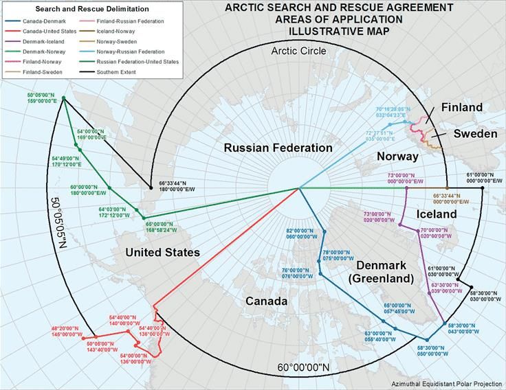
Figure 11: Arctic Search and Rescue agreement areas of application (FBG, 2017) ................ 27
Figure 12: The Clipper Adventurer (TSB, 2012) ..................................................................... 31
Figure 13: Fault Tree Analysis of the Clipper Adventurer grounding ..................................... 33
Figure 14: Reliability Block Diagram of the Clipper Adventurer grounding .......................... 34
Figure 15: Illustrative AHP model of the Clipper Adventurer grounding ............................... 38
Figure 16: AHP model of the direct causes of the Clipper Adventurer grounding .................. 39
Figure 17: AHP model of the contributing factors of the Clipper Adventurer grounding ....... 42
xiv1 Introduction
1.1 Background
The polar cruise shipping segment, including large cruise ships as well as small- and mid-size
cruise and explorer ships, is continuing to grow. Many cruise companies offer cruises to polar
destinations, and in 2019 more than 500 000 passengers are expected to call at the 12 ports
that are members of Cruise Northern Norway and Svalbard (CNNS, 2019). Judging by the
orderbook of Norwegian shipyards (NSF 2018, Norsk Industri 2018) there has been an
increase in orders for cruise ships with length over 40 meters since 2015, shown in yellow in
figure 1. Furthermore, the Cruise Ship Orderbook (CIN, 2019) show that there are over 40
planned small to medium sized expedition ships over the next 5 years, many of which have
high ice-class. No doubt, the remoteness and characteristics of the polar areas make them
exotic travel destinations and the accessibility to these destinations is improving due to ice
melting. The tendency further shows that a larger part of the shoulder season is utilized, and
some operators are also offering winter cruises.
Figure 1: Orderbook for Norwegian Shipyards (Norsk Industri, 2018)
There are several challenges to consider when operating in polar waters. The previously
mentioned accessibility is followed by the lack of, or poor, hydrographic data in both the
newly ice-free areas and a generally large part of the waters in the polar areas. The maritime
and communication infrastructure is limited. The remoteness and extreme met-ocean
conditions are factors of concern for the officers on board the ship as well as stakeholders and
search and rescue (SAR) entities.
1International standards and regulations adopted by the International Maritime Organization
(IMO) contribute to the mitigation of the risks involved with ship operations worldwide.
Today’s maritime safety regime is a result of several major accidents in shipping where
human errors and management faults have been identified as the main causes. The
International Safety Management (ISM) Code introduces an enforced self-regulatory
mechanism where the shipping companies themselves are to regulate their own activities
(Batalden, 2015). This is achieved through a safety management system (SMS). In 2017,
more specific standards were made mandatory for ships operating in polar waters, introducing
the Polar Code. The Polar Code contains strengthened requirements for the ship and its crew
and acknowledges the extra sensitive environment and conditions in the Arctic and the
Antarctic compared to other areas. The new standards include important improvements such
as new systems and equipment on board the ship, new requirements to life-saving appliances
(LSAs), new criteria for the design and construction of ships as well as risk assessments,
procedures, manuals and additional officer training (IMO, 2016).
Several projects have investigated, and are still investigating, the challenges related to
increased activity in the polar areas. Many of these projects are related to each other. Main
examples to include are the SAR exercises SARex Spitzbergen (Solberg et.al, 2016), SARex
2 (Solberg et.al, 2017) and SARex 3 (Solberg and Gudmestad, 2018). The SARex project is
closely related to the implementation of the Polar Code, as it aims to investigate some of the
functional requirements that are introduced. Other projects are the SARiNOR project
(SARINOR, 2018) which focuses on the general SAR challenges in the Arctic as well as
preparedness related to the environment and pollution, and the ongoing SARex Svalbard
project (Rederiforbundet, 2019) which involves full scale exercises in a polar environment.
The SARex Svalbard project is a follow-up project from both the SARiNOR project and the
SARex project and involves many of the same participants. Also ongoing is the ARCSAR
(Arctic and North Atlantic Security and Emergency Preparedness Network) project, where the
main goal is to establish a network of government, organizational and front-line stakeholders
to meet the challenges following the increased activity in the Arctic (ARCSAR, 2019;
Appendix C).
Today, the key maritime safety challenges in Norwegian waters are crew experience, training
and expertise, bridge manning and Bridge Resource Management (BRM), fatigue, personal
factors, stress and commercial pressure and confined and complex waters (NCA, 2015).
2Combining the maritime safety challenges with the increased activity, utilizing larger parts of
the shoulder season including winter cruises, and new regulations in the polar areas, it is no
doubt that they will influence each other. The importance of preventive actions towards
mitigating risks is clear, and this thesis aims to highlight these. The objective for serious
operators should be to operate in polar waters at the same risk level as in other waters by
appropriate treatment and mitigation of additional risk factors, as illustrated in figure 2.
Figure 2: Arctic Risk Factors (DNVGL, 2008)
1.2 Scope and Research Theme
The mandatory Polar Code has forced shipping segments operating in polar waters to
implement a new operational framework. This involves new operational assessments, new
manuals and procedures, as well as new training and certification for the crew.
The main research theme for this thesis is how the polar cruise shipping segment is
implementing the Polar Code. From this research theme I have derived two research
questions:
RQ1: What are the challenges related to the implementation of the Polar Code?
RQ2: How are previous lessons learned, non-conformities and near misses used in the
implementation of the Polar Code?
3The aim of the thesis is to provide knowledge about the implementation of the Polar Code in
the polar cruise shipping segment, and to identify challenges related to this process. To
answer the research questions, I have developed a questionnaire (Appendix A) aimed towards
the polar cruise shipping segment. It attempts to identify the challenges in the Polar Code, and
to gain knowledge on how the process of implementing the new regulations are conducted.
Furthermore, the questionnaire aims to identify how previous lessons learned, non-
conformities and near misses are utilized in developing new or updating existing manuals and
procedures.
Further, a root cause analysis of a cruise vessel grounding in the Canadian Arctic is
conducted, using methods from reliability engineering. A review of relevant theory and
literature has been undertaken, and the findings from the survey and the root cause analysis
are discussed.
1.3 Limitations
Geographically, the thesis is limited to the extent of Arctic waters according to the Polar Code
(IMO, 2016), however it can also be relevant for the Antarctic waters as well as areas with
similar characteristics such as the coast along Northern Norway. The incident analysed in this
thesis occurred in the Canadian Arctic where the geographical remoteness and enormity are
particularly evident. Furthermore, the thesis will focus on the polar cruise shipping segment.
Both the root cause analysis and the discussion of survey may be subject to the author’s
predispositions and understanding of the context. This bias is hard to avoid when working
alone.
1.4 Structure
Chapter 1 – Introduction describes the background for the thesis and explains the research
theme and the research questions. The scope of the thesis as well as the limitations is also
described here.
Chapter 2 – Methodology explains the different methods used in the thesis. Both the overall
case study method and the approach towards the survey is described, as well as the different
logical models utilized in root cause analysis, risk analysis and risk assessment.
4Chapter 3 – Maritime Safety contains the description of safety management and relevant
regulations, and the maritime safety challenges are explained. Relevant terms for the root
cause analysis are also described here.
Chapter 4 – Root Cause Analysis of the Clipper Adventurer Grounding is an analysis of the
incident using the Hybrid Model. The findings from the accident report are utilized in
reliability engineering models to enhance the ability to extract lessons learned to prevent an
incident from reoccurring.
Chapter 5 – Results and Discussion presents the findings from the root cause analysis and
the survey and discuss them in relation to the maritime safety challenges.
Chapter 6 – Summary and Concluding Remarks summarizes the work and addresses the
main conclusions related to the research questions. Finally, topics for further work are
suggested.
56
2 Methodology
2.1 Case Study
The scope of a case study is described as “an empirical enquiry that

   •   investigates a contemporary phenomenon (the “case”) in depth and within its real-
       world context, especially when
   •   the boundaries between phenomenon and context may not be clearly evident” (Yin,
       2014).

It is not only a method of approach or data collection, but a comprehensive method for
covering all aspects of a study such as design, data collection techniques and approaches to
data analysis.

A case study can combine qualitative and quantitative methods or consist of one or the other.
A qualitative method is used on small groups or few subjects, is more in-depth and provides
more detailed descriptions of events and experiences. A case study can be descriptive
(describes the “case” in its real-world context), explanatory (explains how or why some
condition came to be) or exploratory (identifies the case and provides basis for further
studies). In addition, a case study is appropriate when the research questions start with “how”
or “why” (Yin, 2014).

This thesis is designed as an exploratory case study, to identify how the polar cruise segment
is implementing the Polar Code. The method for data collection is a qualitative open-ended
questionnaire, seeking out qualitative information from experienced respondents.
Furthermore, a root cause analysis is conducted on a relevant incident for explanation
building and to provide a basis for further discussion. Logic models are utilized for the
validity of the research design, and relevant theory is undergone for discussion and analysis of
the research questions.

Some of the challenges when following a case study approach can be to remain rigorous and
follow a procedure, generalizing from a single case, the resulting in massive unreadable data
and that it can be unclear how the method is favourable to other methods (Yin, 2014). Using
the case study approach for this thesis is a choice based upon the suitability for the approach
when searching for “how” and “why”.

                                               7
2.2 Survey
The questionnaire used for the survey is developed from the research questions, where the
aim is:
• To explore how a company in the polar cruise shipping segment approaches the
implementation of the Polar Code.
• To identify to which degree previously reported non-conformities and accidents are
considered when developing the Polar Water Operation Manual (PWOM).
The desired respondents for the survey are primarily from the polar cruise shipping segment.
The company Health, Safety, Environment and Quality (HSEQ) manager/director or
equivalent position as well as a representative from one of the ships in the company,
preferably a master, are the ideal respondents. By acquiring data from these two perspectives
within the company, the intention is to identify any potential differences in perceiving the
challenges. The interview guide (Appendix A) provides the basis for the questionnaire and
later analysis of the data and an informative text is included to explain the scope and purpose
of the survey, as well as confidentiality and contact information. The questionnaire itself is
made in Google Docs.
For this survey, the main challenge proved to be the number of respondents from the desired
shipping segment – polar cruise. Distribution of the survey towards the polar cruise shipping
segment was conducted through the Association of Arctic Expedition Cruise Operators
(AECO), as they sent an invitation to their members with an informative text and the link to
the questionnaire. Unfortunately, no AECO members responded to the survey. More direct
efforts towards the polar cruise shipping segment were made with assistance from my
supervisors and their network, with little luck. Because of this, none of the respondents are
from the polar cruise shipping segment.
The survey still received good responses. Respondents from academia as well as masters and
other experienced officers with extensive knowledge of ice operations have submitted their
opinions. It has proven valuable to gain the perspective of other shipping segments in this
matter, as many interesting opinions and experiences came to light. Chapter 5 gives a
presentation of the findings from the survey.
82.3 Risk Analysis and Risk Assessment
Kristiansen (2005) explains risk analysis as the process of calculating risk for the identified
hazards, while risk assessment is the process of using the results obtained in the risk analysis
to improve the safety of a system through risk reduction. There are many methods for
identifying the hazards and unwanted events that may influence an object or a process,
including the related causes, probabilities and consequences. Examples of such methodology
are Preliminary Hazard Analysis (PHA), Hazard and Operability studies (HAZOP), Hazard
Identification (HAZID), Failure Mode, Effect and Criticality Analysis (FMECA), to mention
some common ones. They all share many similarities, but the key is to have a structured
approach towards the case at hand and to get some sort of overview in the end. Identifying
hazards can be difficult work, it can tend to be subjective and is often restricted to the authors
knowledge and understanding of the case (especially when conducted alone). Therefore,
interdisciplinary groups of experts are usually working together to identify hazards.
Put in simple terms, risk is the product of probability multiplied by consequence. To illustrate
this, it is common to use a risk matrix, as seen in table 1. The size of the matrix is optional,
but a bigger matrix can prove to be more accurate. The red area indicates unacceptable
conditions and risk reducing measures are required. The yellow area indicates tolerable
conditions, but risk reducing measures should be considered. Within the green area the
conditions are acceptable, and we do not need to consider any risk reducing measures.
Table 1: Example of a 5x5 risk matrix
Consequence → Minimal Low Medium High Very high
Probability ↓
Very high
High
Medium
Low
Minimal
92.4 The Hybrid Model for Root Cause Analysis
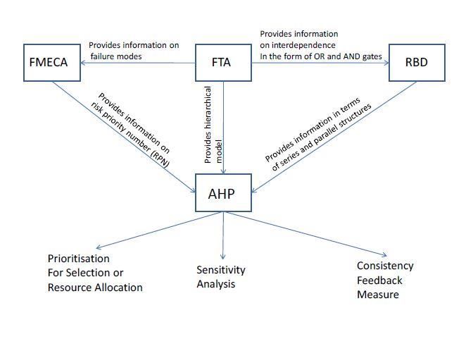
Labib and Read (2015) propose a thorough and integrative approach to perform a systematic
analysis of a disaster, which can lead to learning from failures. The tools in this hybrid model,
as shown in figure 3, are frequently used in reliability engineering, and utilizes Fault Tree
Analysis (FTA), Reliability Block Diagram (RBD), the Risk Priority Number (RPN) concept
and Failure Mode, Effect and Criticality Analysis (FMECA) together with the Analytic
Hierarchy Process (AHP).
Figure 3: The Hybrid Model Structure (Labib and Read, 2015)
An incident involving the grounding of a large cruise vessel in the Arctic possesses the
potential of all three attributes of a disaster; rarity, extreme impact and retrospective
predictability (Taleb, cited in Labib and Read, 2015). According to Labib and Read (2015)
the analysis of disasters, or in the case of this thesis, an incident involving the grounding of a
cruise vessel in the Arctic, can produce four main benefits. Firstly, identifying the root causes
of what went wrong and why. Secondly, act as an early warning signal prior to the event to
take pre-emptive measures. Thirdly, to institute long term plans to prevent similar events from
re-occurring. Fourthly, to provide decision makers with a set of priorities for resource
allocation for both recovery and prevention.
10By integrating tools from reliability and systems engineering, we can structure the events
leading to the disaster and identify the root causes. The different tools in the model are
presented below, attempting to explain the basic concepts. The Hybrid Model is used for the
root cause analysis in chapter 4. Figures used in the thesis that are not gathered elsewhere and
contain a reference, are made by the author utilizing the software Edraw Max Pro v. 9.4.
2.4.1 Failure Mode, Effect and Criticality Analysis
The Failure Mode, Effect and Criticality Analysis (FMECA) approach is a valid tool for
performing a risk assessment on a system, and it is very straight forward. It provides a good
overview of the system and the different risks associated with the different
modules/components/actions. The stages of the approach can be described as follows
(Kristiansen, 2005):
• A general description of the components
• Description of possible failures and failure modes
• Description of failure effects for each failure mode
• Grading the failure effects in terms of severity, occurrence and difficulty of detection
(or other parameters if deemed more relevant)
• Specifying method for detection of failure modes
• Description of how unwanted failure effects can be reduced and eliminated
Risk Priority Numbers (RPN) can be used in an FMECA, as they can give us an idea of the
risks that should be prioritized. Table 2 illustrates an RPN scaling from 1 to 5. The approach
can be qualitative or, if enough data is available, the approach can be quantitative, and a
different scale can be utilized.
Table 2: Example of RPN of severity(S), occurrence(O) and Detection(D)
Rank Severity (S) Occurrence (O) Detection (D)
1 No effect on the system Failure is unlikely Certain detection of
performance weakness
2 Slight deterioration of the Relatively few failures Good chance of detection
system
3 Noticeably deterioration Occasional failures May detect weakness
of the system
4 Failure subsystem Repeated failures Not likely detection of
weakness
5 Affects human safety Failure is inevitable Cannot detect weakness
112.4.2 Fault Tree Analysis
The Fault Tree Analysis (FTA) is a method used for analysing how unwanted events occur, as
well as its causes (Kristiansen, 2005). It is a top-down approach for failure analysis, starting
with an unwanted event (top event) and tracing the lower level events (intermediate events) to
identify sub-systems and all the different causes (basic events) leading up to the top event, as
illustrated in figure 4.
Figure 4: Principles of a fault tree (Kristiansen, 2005)
The approach can be quantitative or qualitative. The quantitative approach uses the failure
probability of the basic events and the fault tree gates to calculate the probability of the top
event, followed by an assessment by using an importance measure for each basic event. The
qualitative approach starts by describing the system and its subsystems and components down
to enough level of detail, then continues by constructing the fault tree for the top event by
using this description. The AND/OR gates describe the fault logic between the events. I.e. an
OR-gate implies that the output event is dependent on one of the two basic events to occur.
The AND-gate implies that the output event is dependent on both basic events to occur. An
example of a simple Fault Tree Model is given in figure 5 below.
12Figure 5: Example of a Fault Tree Model
2.4.3 Reliability Block Diagram
The Reliability Block Diagram (RBD) gives additional value to the analysis by providing
decision makers with better understanding of the overall reliability of the model by
highlighting vulnerable series structures and safer parallel structures (Labib and Read, 2015).
Giving the different components a reliability value, we can calculate the system reliability. To
increase system reliability, the number of components in series should be kept to a minimum.
Used together with an FTA, the AND-gates are considered parallel structures and the OR-
gates are considered series structures. Figure 6 show an example of an RBD of a system.
13Figure 6: Example of a Reliability Block Diagram (RBD)
2.4.4 Analytical Hierarchy Process
The Analytical Hierarchy Process (AHP) is a Multi-Criteria Decision Making (MCDM)
method. Complex decision-making needs organized creative thinking to structure the
problem, and this structure can be provided by a hierarchy or a network (Saaty, 2013). It also
needs numbers and mathematics to formalize judgements and make trade-offs. The objective
of the AHP is to act as a mental model and for prioritisation to help decision makers
understand the environment in question (Labib and Read, 2015). The decision makers are to
provide judgements about the relative importance of each criteria, and then specify a
preference on each criterion for each decision alternative.
An example of a three-level hierarchical model based on an AHP is illustrated in figure 7. The
goal is what we want to achieve. There are three different alternatives to choose from and two
criteria for choosing among the alternatives. Default priorities are shown as numbers in the
boxes, i.e. they are equally prioritized. The sum of each level is always 1.
14Figure 7: Example of a three level Analytical Hierarchy Process (AHP) model
The prioritization in the hierarchy is, as for the previous methods, either a qualitative process
based on experience and the author’s understanding of the criteria, or a quantitative process
when appropriate data is available. A pairwise comparison is made with respect to the level
above, i.e. the criteria are compared with respect to the goal while the alternatives are
compared with respect to the criteria. The scale utilized when comparing is an absolute scale
of numerical numbers ranging from 1 to 9, where each value explains how the component
contributes to the objective compared to the other. The definitions are: equal with (value 1),
moderate with (value 3), strong with (value 5), very strong with (value 7) and extreme with
(value 9) and the integers between for compromise, and their reciprocals (Saaty, 2013).
The weakness of the AHP is the dependency on the judgement of the person performing the
analysis. This is mitigated by using expert groups agreeing upon the scores (Stephen and
Labib, 2017).
The priorities are derived by using the traditional AHP eigenvalue method (Stephen and
Labib, 2017), and the calculations of the eigenvalue in this thesis are made using an online
AHP Priority Calculator (AHPPC, 2017). For a thorough review of the AHP approach, please
consult Saaty (2013).
In the context of the root cause analysis, the FTA model is used as the hierarchical model and
the alternatives are other common factors to consider when trying to solve the basic events
(Stephen and Labib, 2017). A full example of the method is given in chapter 4.
1516
3 Maritime Safety
3.1 Safety Management
The objective of safety management is to ensure the safe and efficient execution of an
operation and should therefore be considered an essential and integral element of the overall
management system of an organization (Kristiansen, 2005). The maritime safety management
regime, i.e. the rules and regulations governing safety and environmental protection in
shipping, have evolved over time. Kristiansen (2005) explains three stages of evolution.

Stage one is the early, basic stage which focused on the consequences of accidents resulting
from safety related failures. In the aftermath of accidents, major efforts were made to find
someone to blame for all the material, environmental or human casualties. There was a
culture of punishment that identified and allocated blame, and frequently this was the people
at the sharp end of the system, e.g. a ship officer.

Stage two is the regulation of safety by prescription, i.e. the rules and regulations the maritime
industry must obey. The International Convention on Load Lines (ILLC), the Convention on
the International Regulations for Preventing Collisions at Sea (COLREGs), the International
Convention for the Safety of Life at SEA (SOLAS), the International Convention on
Standards of Training, Certification and Watchkeeping for Seafarers (STCW) and the
International Convention for the Prevention of Pollution from Ships (MARPOL) form the
basis for the prescriptive regulatory framework in shipping today. The prescribing party in the
case of the maritime industry is the International Maritime Organization (IMO), a United
Nations agency. The regime affects a vessel in all its life cycle, from design and construction
via operation and modification to decommissioning. This result in a culture of compliance.

Stage three is the culture of self-regulation, which concentrates on internal management and
organization for safety, and encourages the establishment of targets for safety performance.
Self-regulation emphasizes the need for every organization and individual to be responsible
for the actions taken to improve safety. This requires the development of company-specific
and vessel-specific safety management systems (SMS). Safety is in other words organized by
those who are directly affected by the implications of failure.

                                                17
Kristiansen (2005) also argues that these three stages must coexist to achieve safer seas, as
each regime plays a significant part in influencing company and individual behaviour. The
causal factors resulting in ship accidents indicates a potential for improvement related to
human and organizational factors.
3.2 Regulations
The codes issued by IMO can be considered as more detailed and specific guides to achieving
the aims of the conventions, such as the International Safety Management (ISM) Code and the
Polar Code which are the most relevant for this thesis. The ISM Code and the Polar Code are
mandatory under SOLAS, STCW and MARPOL, as they regulate safety, training,
certification and environmental issues related to ship operations. The main purpose of both
the ISM Code and the Polar Code is to provide an international standard for safety
management, ship operations and pollution prevention in shipping.
3.2.1 The ISM Code
The objective of the ISM Code is to “ensure safety at sea, prevention of human injury or loss
of life, and avoidance of damage to the environment, in particular the marine environment,
and to property” (IMO 2018).
To achieve this objective, the ISM Code proposes the establishment of an SMS. There are 12
sections in part A of the ISM Code, which goes into detail on what the SMS should contain.
Part B consists of 4 sections which regards certification and verification. The SMS provides a
shipping company with a system that can greatly contribute towards identifying hazards,
mitigate risks and optimize procedures. The ISM Code applies worldwide.
A shipping company must possess a Document of Compliance (DOC) as well as a Safety
Management Certificate (SMC) to operate vessels in compliance with the ISM Code.
3.2.2 The Polar Code
The aim of the Polar Code is to “provide for safe ship operation and the protection of the
polar environment by addressing risks present in polar waters and not adequately mitigated
by other instruments of the Organization” (IMO 2016).
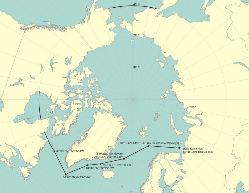
The Polar Code applies to ships operating in polar waters, which is defined in the code and
illustrated in figure 8 and 9 (IMO, 2016).
18Figure 8: Arctic - The waters north of latitude 60°N, with deviations to include waters around the southern
exposure of Greenland, but excluding those around Iceland, the Norwegian mainland, Russia’s Kola Peninsula,
the White Sea, the Sea of Okhotsk and Alaska’s Prince William Sound. (IMO, 2016)
Figure 9: Antarctic - All waters south of latitude 60°S (IMO, 2016)
19The Polar Code acknowledges the extra sensitive marine environment and hazardous
conditions in the Arctic and Antarctic compared to other areas, hence the strengthened
requirements to a ship and its crew. The Polar Code consists of part 1 A and B, as well as a
part 2 A and B. Part 1A addresses safety measures through 12 chapters, while part 1B are
recommendations. Part 2A addresses pollution prevention through 5 chapters, where part B
also provides recommendations. Some key requirements in the Polar Code are:
• Perform an Operational (Risk) Assessment
• Development of a Polar Water Operation Manual (PWOM)
• Carry a Polar Ship Certificate (PSC)
• Carry the appropriate training certificates
• Voyage planning to avoid areas with poor hydrographic data, remoteness ice and/or
met ocean conditions that exceed the ship's design capabilities or limitations
These requirements demand new documentation in order to operate in compliance with the
Polar Code, as well as additional training of the ship officers. Other requirements are related
to ship structure, stability, safety regarding navigation, fire, life-saving appliances (LSAs), as
well as machinery and communication.
To establish procedures and operational limitations, an assessment of the ship and its
equipment should be conducted. The Polar Code include guidance for an operational
assessment (IMO, 2016):
• Identify relevant hazards from section 3 of the Introduction and other hazards based
on a review of the intended operations
• Develop a model to analyse risks considering (Refers to Formal Safety Assessment
(FSA)):
o development of accident scenarios
o probability of events in each accident scenario
o consequence of end states in each scenario
• Assess risks and determine acceptability:
o estimate risk levels in accordance with the selected modelling approach
o assess whether risk levels are acceptable
20• In the event that risk levels determined in steps 1 to 3 are considered to be too high,
identify current or develop new risk control options that aim to achieve one or more of
the following:
o reduce the frequency of failures through better design, procedures, training,
etc.
o mitigate the effect of failures in order to prevent accidents
o limit the circumstances in which failures may occur
o mitigate consequences of accidents
o incorporate risk control options for design, procedures, training and
limitations, as applicable.
This will form the basis for the Polar Water Operation Manual (PWOM), where the goal is to
provide the owner, operator, master and crew with sufficient information regarding the ship's
operational capabilities and limitations in order to support their decision-making process
(IMO, 2016). It is a ship specific document that describes how to operate the ship in polar
waters. The PWOM must include risk-based procedures, which considers each hazard
identified as relevant in the operational assessment, and it is meant to act as a supplement to
the Polar Ship Certificate (PSC). An example of how the table of contents for a PWOM can
look like is given in Appendix D (ABS, 2016).
The PSC is issued by a vessel’s flag administration or its authorized representatives. It will
verify that the vessel has conducted the necessary assessments and actions to operate in polar
waters and complies with the Polar Code. The PSC will, among other information, contain
specific information on the operational limitations of a vessel for ice conditions, temperature,
latitude and expected time to rescue (IMO, 2016).
The new requirements for LSAs derive from the definition of maximum expected time of
rescue in the Polar Code section 1.2.7. (IMO, 2016): the time adopted for the design of
equipment and system that provide survival support. It shall never be less than 5 days. Three
large live search and rescue (SAR) exercises have been conducted in the Svalbard area
involving major actors from the Norwegian government, foreign and domestic academic
institutions, as well as representatives from equipment manufacturers. The scope of these
exercises has been to explore the gaps between existing SOLAS-equipment and the required
Polar Code-equipment, where the functional survival requirement of 5 days after abandoning
ship is at the centre. Important findings from these exercises involve the complicated
21mechanisms at play when surviving in a polar environment (equipment/functionality,
mental/physical robustness, decision making, small error-margin), as well as the need for
adequate training and education for the crew (Solberg, Gudmestad and Kvamme, 2016;2017;
Solberg and Gudmestad, 2018).
The Polar Code is made mandatory for new ships from January 1st 2017, and ships
constructed before January 1st 2017 will be required to meet the relevant requirements of the
Polar Code by the first intermediate or renewal survey after January 1st 2018. The
requirements on the crew members are enforced from July 2018.
3.2.3 Other Relevant Regulations, Systems and Guidelines
The Norwegian Maritime Authority (NMA) currently have additional rules for passenger
ships operating in the Norwegian territorial waters around the Svalbard archipelago (NMA,
2017). This is currently only a circular however, a consultation regarding the forthcoming
Regulations on the construction, equipment and operation of passenger ships in the
Norwegian territorial waters surrounding Svalbard (NMA, 2019) was recently distributed.
The deadline for inputs was set to March 3rd, 2019, and the regulation is scheduled into force
on January 1st, 2020. These regulations will replace the circular.
The forthcoming regulations aim to raise the minimum safety standard requirement on
passenger ships in the Norwegian territorial waters surrounding Svalbard. Important issues
such as voyage planning and monitoring, minimum distances to glacier fronts, hospital
accommodation, helicopter evacuation procedures, specific requirements to tenders, life-
saving appliances, construction, communication, navigation safety, safety management and
safety measures in polar waters are addressed (NMA, 2019). It is worth noticing that the
maximum expected time of rescue is defined differently in the draft of these regulations than
in the Polar Code: The time adopted for the design of equipment and systems that provide
survival support and could be less than 5 days (NMA, 2019).
Canada and Russia have enforced regulatory standards in the Arctic for several years, having
their own systems for ensuring safe operations in ice covered waters. The Canadian Arctic Ice
Regime Shipping System (AIRSS) and the Russian Northern Sea Route Administration
(NSRA) are administrating the functions of issuing permits and certificates, researching met-
ocean conditions, coordination of icebreaker services etc. They also have methodologies in
place for assessing the structural capabilities and limitations in different ice regimes and
22You can also read