The Design, Development and Commissioning of a 2 kNm Torque Standard Machine
←
→
Page content transcription
If your browser does not render page correctly, please read the page content below
The Design, Development
and Commissioning of a
2 kNm Torque Standard Machine
Andy Robinson
National Physical Laboratory
United Kingdom
This paper describes NPL’s 2 kN·m torque machine — the UK’s first national torque standard — a lever deadweight
machine with a vertical torque axis and an uncertainty of ±0.002 %. Despite the greater difficulty in applying torques
to a vertically mounted transducer, this design was selected as it enables a symmetric “pure” torque to be applied. In
addition, this design provides adaptability, enabling comparisons with the application of asymmetric torque and “on-the-
fly” torque calibrations to be studied. The vertical transducer orientation is made possible through several innovative
sub-assemblies, including boron fibre tapes and a twin-beam carbon fibre lever, both developed within NPL. The machine
will be used to calibrate transducers and to disseminate the unit of torque within industry.
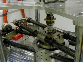
Introduction machine. The provision of this calibration lever beam (see Figure 1). Most torque
machine was welcomed by UK industry standard machines are designed with a
From the tightening of wheel nuts with much consultation during the horizontal torque axis because this is the
on an automobile to the assembly of conceptual design stage. The aim of the most simple and direct way of applying
caps for pill bottles, or maximising project was to create a torque calibration torque. The disadvantage is that a force
the output of an internal combustion machine of the highest accuracy, which produced from a single weightstack
engine, the accurate measurement of would then be used to calibrate transfer will produce a bending moment
torque is essential to UK industry. The devices to disseminate the unit of torque that can affect the transducer under
need to provide national standards for within industry. test. A vertical torque axis machine
torque was recognised by the UK’s can produce equal and opposite
Department of Trade and Industry
Conceptual Design forces via two identical weightstacks
when the National Physical Laboratory The 2 kN·m torque machine, designed at either end of a lever beam —
(NPL) was commissioned in 1996 with a vertical torque axis, generates a the moments cancel out to leave a
to design and manufacture the first symmetric pure torque via identical symmetric pure torque. A complication
national standard torque calibration weightstacks located at either end of a arises from the need to convert the
vertical force generated
by the weightstack
into a horizontal force
transferred to the lever
beam. This is achieved
via an arrangement of
boron fibre tapes and a
pulley air bearing.
The need to apply
clockwise and anti-
clockwise torque
loading provided
additional complexity
to the pulley system
design. This was
overcome by designing
a lever beam that can be
rotated independently
Figure 1. Views of the NPL static torque calibration machine.
31 Jan • Feb • Mar 2007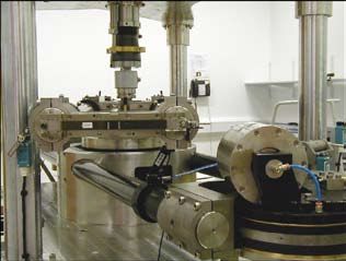
The Design, Development and Commissioning of a 2 kNm Torque Standard Machine
Andy Robinson

             Figure 2. Views of the end of the machine showing the transfer of the force.

   of the torque transducer, to two neutral positions either          with minimal friction, to achieve their target uncertainty
side of a pulley system. This arrangement necessitates the            range of (0.1 to 0.5) µN·m. Friction within a hydrostatic air
pulley system to be castored to enable rotation about its             bearing is a combination of boundary and viscous shear of
vertical axis such that the force axis remains unchanged for          the air film plus turbine torque.
both clockwise and anti-clockwise torque application.                    Both the boundary and viscous shear influences are time
   The photographs of the 2 kN·m torque calibration                   dependent, such that once the lever beam has been driven to
machine (Figures 1 & 2) show a twin beam construction                 its measurement position by the reaction drive gearbox and
with castored pulley bearings mounted on a reaction beam.             stopped, subsequent relaxation within the air film occurs
Identical materials are used for both beams so that thermal           and zero friction will be detected. However, the reaction
effects will be identical, thus minimising errors of pulley           of the airflow as it is discharged through orifices into the
misalignment relative to the lever beam.                              bearing clearance can impart a low but detectable turbine
   The primary range of the machine from 40 N·m to                    torque within the bearing. If the bearing does not rotate
2000 N·m has 15 torque increments. A pair of smaller                  but acts as a low friction pivot, as in the case of this torque
weightstacks provides a secondary range with 14 further               calibration machine, it is necessary to evaluate and minimise
torque increments between 2 N·m and 100 N·m.                          the friction attributable to turbine torque.
   The machine can also be used for continuous torque                    The central pivot air bearing (Figure 3) is a double journal
calibration. The lever beam can be mechanically locked and            and thrust air bearing system that can be air energised
the reaction drive gearbox then used to generate a torque             separately. The upper bearing enables the rotation of the
controlled by a reference transducer. This enables a torque           lever beam to enable clockwise and anti-clockwise torques
calibration to be produced in a fraction of the time taken            to be applied without disturbance to the transducer. The
for an equivalent static calibration.                                 lower main bearing is pivotal to the performance of the
   The machine is PC controlled through a Visual Basic                torque machine and must operate with near zero friction.
6.0® program. This provides a graphical user interface                Incorporated into the bearing design is a drag-cup damper
and enables complicated motion sequences to be compiled.              to compensate for the dynamic natural frequency of the lever
The weightstack platforms slow as each weight is added                beam system. The results from the FEA analysis of the modal
or removed, minimising inertial effects. After a weight is            frequency response of the beam sub-assembly were used as
either added or removed the reaction drive gearbox drives             the input to optimise the damper design.
the lever beam back to its datum position. The software                  The balancing of the central pivot air bearing was carried
gives the operator real time information on the status of             out with its spin axis horizontal, although in operation the
the machine.                                                          spin axis is vertical. Assuming the bearing operates vertically
                                                                      to within ± 0.5º, then this out-of-balance component will
Air Bearings                                                          be 3.6 µN·m. In operation the bearing is deployed in one
                                                                      position and this dictates the positioning of the air slip rings
  Design of the air bearings for both the central pivot of the
                                                                      that distribute the supply air to support the lever beam
lever beam and the castored pulley systems will influence
                                                                      assembly. The turbine torque is minimised by optimising
the uncertainty of torque measurement [2]. The prime
                                                                      the air supply pressure, the requirements of which are
requirements were that the air bearing systems provide both
                                                                      dependent upon the magnitude of the applied torque. The
radial and axial stiffness to support the predicted forces,
                                                                      magnitude of the turbine torque was therefore evaluated

                       Jan • Feb • Mar 2007                      32
The Design, Development and Commissioning of a 2 kNm Torque Standard Machine
                                                                                                         Andy Robinson

                                                                                            m. The design specification required
                                                                                            that the beam sub assembly is of a
                                                                                            lightweight construction to reduce
                                                                                            inertia and to have a very low deflection
                                                                                            under load. Thermal expansion of the
                                                                                            beam is also considered critical [3].
                                                                                               In consultation with NPL colleagues
                                                                                            working in materials research, it was
                                                                                            agreed to use two parallel 2 m long,
                                                                                            high-modulus carbon fibre tubes with
                                                                                            stainless steel end fittings and central
                                                                                            boss. Onto the end fittings, connectors
                                                                                            are attached for the application of the
                                                                                            weightstacks. The steel central boss and
                                                                                            end fittings are clamped and pinned,
                                                                                            using 12.5 mm taper dowels, such that
                                                                                            the expansion of the steel components
                                                                                            will have minimal effect on the overall
      Figure 3. The central air bearing; photograph of the castored pulley bearing.         expansion of the beam. Expansion of
                                                                                            the beam will also be minimised by a
over the angular position of bearing           application. This application of a           laboratory controlled to a temperature
operation and at an air supply pressure        torque moment necessitates that the          of (20 ± 0.5) °C. The identical material
ranging from 280 kPa to 480 kPa.               main bearing is also able to resist          construction of the lever and reaction
   At this pressure the shaft of the           bending forces. To monitor the effect        beam sub-assembly minimises the
bearing rotated in an anti-clockwise           of bending forces on deflections within      thermal effects on the alignment of
direction when viewed from above               the air film, two pressure sensors           the castor pulley system to the lever
due to the generated turbine torque.           were positioned within the lower             beam reference axis. Furthermore
The magnitude of the turbine torque            thrust main bearing. The first pressure      all dimensional measurements are
was evaluated by measurement of                tapping is positioned at 7.5º from the       referenced to the central axis of the pivot
the bearing acceleration and the force         radial plane and the second at 90º           bearing and allow for the sub-assembly
required to stop rotation and hold             from the first. To simulate the mass of      to be measured off the machine.
the bearing in balance. The bearing            the lever beam an axial force of 912 N          The lay of the carbon fibre was
balance force was determined using a           is applied, whilst the bending forces        designed to minimise thermal
combination of a capacitance probe to          ranged from 400 N to 750 N. The aim          expansion and optimise the
measure displacement and a calibrated          of the test was to apply a bending force     performance of the beams. The
“micro” air jet to provide a reactive force.   until the thrust plate had deflected by      principal longitudinal fibres provide
The results of both studies confirmed          4 µm, i.e. one half of the semi-axial        both rigidity for bending moments
that repeatable, unidirectional turbine        clearance. The results show that the         and a calculated coefficient coeffcient
torque ranging between 200 - 220               higher bearing air supply strategy,          of thermal expansion of -3x10 -7 K-
                                               suggested to provide greater rigidity        1. For the target uncertainty of the
µN·m were recorded dependent upon
the air supply pressure — the higher           to the bearing air film, enabled the         machine to be met, it was calculated
the pressure, the marginally higher            highest bending forces to be supported       that the deflection contribution for
(approx 10 %) the turbine torque.              with minimal variations monitored by         the lever beam and reaction beam
However, as this increase is so minimal        the pressure sensors.                        should not exceed 1.0 mm and 1.1
it is recommended that the higher                 The castor pulley bearing system          mm respectively. Hoop wound fibres
supply pressure is used to ensure              (Figure 3) provides both horizontal          of various orientations maintain the
rigidity of the bearing air film over the      and vertical rotation and is designed        longitudinal fibres, provide additional
30 years predicted life of the torque          to carry a load of 1 kN transmitted by       torsional strength, and provide
calibration machine. For calibrations of       a suspension tape under tension at a         strength in the areas of machining
torque transducers of less than 20 N·m         supply pressure of 345 kPa.                  for the fixing pins to secure the
capacity the turbine torque (220 µN·m)                                                      mounting of the stainless steel central
will need to be considered and “tared”         The Lever and Reaction                       boss and end fittings. Additionally,
such that the target uncertainties of the                                                   the hoop wound fibres provide a
                                               Beam
calibration machine are not exceeded.                                                       reduced thermal expansion in the
   The design of the torque calibration          The design provides a balanced 1 m         radial direction.
machine enables asymmetric torque              long lever beam, i.e. a total length of 2       To provide confidence in the

                                                                  33                  Jan • Feb • Mar 2007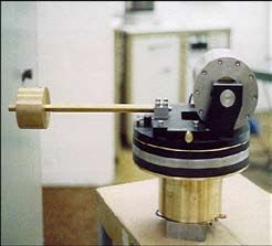
The Design, Development and Commissioning of a 2 kNm Torque Standard Machine
Andy Robinson

                                                                          Tensile strength                       1 520 MPa
                                                                          Tensile modulus                        195 GPa
                                                                          Flexure strength                       1 790 MPa
                                                                          Flexure modulus                        190 GPa
                                                                          Inter-laminar shear                    97 MPa
                                                                          Coefficient of thermal expansion       4.5 x 10⁻⁶ K-1
                                                                          Density                                2.0 x 10³ kg·m-3

                                                                                    Table 1. Properties of boron tape [5].

                                                                         Extensive tensile testing of made-up boron tapes has
                                                                       shown that they have a safety factor greater than 4, whilst
                                                                       creep tests at 1.5 times the maximum applied force (1.5 kN)
                                                                       have recorded an elongation of between 0.04 % and 0.09
                                                                       % dependent on the width of the tape and no measurable
    Figure 4. The lever and reaction beam sub-assembly.                creep after the 40 hour test. The greater elongation was
                                                                       observed with the wider tape and suggests that this may
                                                                       be associated with either the titanium end connector or its
design of the composite lay-up a detailed finite element               bonding to the boron tape.
analysis (FEA) of the lever beam and the reaction beam was               The tape is required to change orientation in the
undertaken [4]. The FEA study predicted that the deflections           horizontal plane in order that it can pass around the
of the beam sub-assembly are within those allowable for the            end radius of the lever beam. The additional weight of
target uncertainty budget of the machine.                              any connectors added to facilitate this change will cause
                                                                       the tape to deviate from the horizontal introducing an
Boron Fibre Tapes
                                                                       error into the transfer of the force. For the 5 mm tape, a
   A problem with the use of deadweights is the uncertainty            preformed 90° twist was put into the tape to eliminate the
(coming from alignment and friction) associated with                   need for any sort of connector. For the larger weightstacks
using a pulley to transform a vertical force to the                    using a 20 mm width tape, a preformed twist was not an
required horizontal force, and the additional effects of               option because of a limit in the length over which the twist
the components used to connect the lever beam to the                   had to take place. An alternative was developed for the 20
weightstack [3].                                                       mm tape whereby a small incision at the end of the two tape
   Accurate measurement and control of the lever beam                  lengths allowed them to be intersected perpendicularly
length as defined by the line of action (reference line) of the        to each other (Figure 5). Bonding short lengths of carbon
applied force must be maintained within a few microns.                 and glass fibre angle onto the area held the intersection
The required material for suspending the deadweights                   length together.
must therefore not deform upon loading, it must be
lightweight, and it must possess the flexibility to ensure
that it conforms to the radii of the end-fitments of the lever
beam and the surface of the castor pulleys.
   Experimental work at NPL identified boron as being
the ideal suspension material and initial studies were
carried out to evaluate a boron fibre foil made up from
individual 0.29 mm diameter mono-filaments. Problems
with handling the multi-fibre foils was of a major concern
and subsequent research identified a suitable boron tape.
This material is an epoxy pre-impregnated tape of 150 µm
boron fibres, produced using chemical vapour deposition
of a boron tri-chloride gas on to fine tungsten wire [5]. The
properties of the boron tape are as shown in Table 1.
   The width of the tape is dependent upon the weightstacks
suspended; a 5 mm tape for the 50 N stack and a 20 mm
tape for the 1 kN stack. The tapes are “sandwiched” and
bonded between a titanium end connector.                               Figure 5. Photograph of the 20 mm width boron tape with 90°
                                                                       joint.

                        Jan • Feb • Mar 2007                      34
The Design, Development and Commissioning of a 2 kNm Torque Standard Machine
                                                                                                         Andy Robinson

Performance and
Uncertainty
   The machine’s uncertainty is defined
as that of the torque generated around
the central axis of the machine. For
the range 40 N·m to 2000 N·m the
relative uncertainty is 2 x 10⁻⁵ for a k = 2
coverage factor, traceable to the base SI
units. The major contributions to the
uncertainty are discussed below.
Force: The uncertainty of the applied
force is derived from the mass
calibration of the weightstacks and
includes contributions from buoyancy           Figure 6. Percentage deviation from a first order straight line fit for clockwise torque.
and magnetic effects.
                                               the derived uncertainty budget. Figure           the financial support of the National
Alignment: Measurements under load             6 summarises the calibration result for a        Measurement System Policy Unit of the UK
are made to ensure the alignment of            reference transducer calibrated in three         Department of Trade and Industry.
the force within required limits taking        orientations, both incrementally and
into account any deflection in the lever       decrementally. The graph demonstrates            References
and reaction beams and any deviation           the repeatability and reproducibility            1. Davis, F. A., The 1st UK National
in the boron tape.                             of the machine together with the                    standard static torque calibration
                                               hysterisis of the transducer. In Summer             machine - new design concepts
Length: The length of the lever beam
                                               2006 the NPL machine will participate               lead the way, Measurement Science
has been measured on a coordinate
                                               in the first CIPM intercomparison in                Conference in Anaheim, USA, 2002.
measuring machine with a relative
                                               the field of torque.
uncertainty of 3.3 x 10⁻⁶. The beam                                                             2. Peschel, D., Mauersberger, D.,
length, including half the thickness of                                                            Determination of the Friction of
the boron fibre tape, gives a nominal          Conclusions
                                                                                                   Aerostatic Radial Bearings for the
overall lever arm length of 1.000 000 m.          Commissioning of the machine was                 Lever-Mass Sytem of Torque Standard
To ensure the constancy of the length,         completed at the end of the 2005 and                Machines, Proceedings of the 13th
a series of tooling balls mounted along        a torque transducer calibration service             IMEKO World Congress, (September
the lever beam are measured regularly          has been subsequently launched. It is               5-9, 1994, Torino, Italy) pp. 216-220.
with a length comparator, which                expected that the dissemination of the
compares the distances to a reference          unit of torque will have a significant           3. Smith, J. D., Practical Problems in
standard.                                      impact within industry. Using a novel               Calibration of Torque Tubes, Strain,
                                               and innovative design, the machine                  Oct. 1977, pp. 148-151.
Friction: Friction is minimised through
the use of the central air bearing on          has met its design target in realising           4. Marks, L., Greensmith, B., Sangster, R.,
which the lever beam sits. Air bearings        uncertainties at world leading levels.              & Davis, F. A., Design of the Lever and
also allow the pulleys to rotate freely        The flexibility of the machine will                 Reaction Beams for the UK Torque
while a castor bearing enables rotation        provide a powerful research tool in the             Calibration Machine, IMEKO XVI
around the axis of the weightstack.            field of torque metrology.                          World Congress, Vienna, Austria,
Turbine torque has been experimentally                                                             Sept 2000.
determined at 220 µN·m, for a constant         Acknowledgements
                                                                                                5. Textron Systems, USA. Trade
pressure in the central air bearing. As           This paper is based in part on the earlier
                                                                                                   Literature.
the air pressure is kept constant, this        work of Dr F A Davis [1]. The author would
                                                                                                   _____________________
error can be tared. The level of balance       like to thank the design team for their input,
                                                                                                Andy Robinson, Force Torque and
of the bearing is within 3.6 µN·m. At          in particular Mr R Sangster of Advanced
                                                                                                Hardness Standards, Engineering and
the minimum torque value generated,            Witness Systems Ltd., for his design input
                                                                                                Process Control Division, National
this contributes a relative uncertainty        into this torque calibration machine, Mr P
                                                                                                Physical Laboratory, Hampton Road,
of 1.78 x 10⁻⁶.                                Bird of NPL’s Engineering Services, Dr G
                                                                                                Teddington, Middlesex, United
   Performance of the machine can              Sims and Mr R Shaw of NPL for input on
                                                                                                Kingdom TW11 0LW. andy.robinson@
be independently verified by means             carbon fibre tubes and boron tapes and Mr
                                                                                                npl.co.uk.
of comparison with a machine of                R Woolley of Fluid Film Devices Ltd., for the
similar uncertainty using a reference          design/manufacture of the air bearing.
transducer. Recent work has supported             Finally, the author acknowledges

                                                                    35                  Jan • Feb • Mar 2007
You can also read