Investigation of gas purging and cold storage impact on PEM fuel cell system performance for aeronautical applications
←
→
Page content transcription
If your browser does not render page correctly, please read the page content below
E3S Web of Conferences 334, 06004 (2022)                                                                 https://doi.org/10.1051/e3sconf/202233406004
EFC21

          Investigation of gas purging and cold storage impact on PEM
          fuel cell system performance for aeronautical applications
          Gema Montaner Ríos1,*, Florian Becker1, Anna Vorndran1, Christoph Gentner1 and Syed Asif Ansar2
          1German   Aerospace Center (DLR), Institute of Engineering Thermodynamics, Hein-Saß-Weg 22, 21129, Hamburg (Germany)
          2German   Aerospace Center (DLR), Institute of Engineering Thermodynamics, Pfaffenwaldring 38-40, 70569, Stuttgart (Germany)

                        Abstract. Durability of proton exchange membrane fuel cell systems under cold weather conditions is
                        essential and a critical challenge for transportation applications. During cold storage the water remaining in
                        the cells can freeze causing damage to the cell components. In order to avoid this degradation, fuel cells are
                        commonly purged with dried gases during shutdown prior to its storage at subzero temperatures. This work
                        investigates cold storage of PEMFC systems at temperatures down to -40°C with the aim of developing a
                        shutdown procedure that leads to minimal degradation due to cold storage, while meets energy efficient and
                        time requirements of aeronautical applications. To that end, several experiments were carried out with two
                        different stacks (a 4 kW liquid cooled and a 100 W air cooled) under a wide range of operating parameters:
                        cathode gas, purge temperature, anode and cathode gas purge flow rates, purge time and cold storage
                        temperature. The fuel cell performance degradation due to ice formation was measured by the polarization
                        curves conducted prior and after every F/T cycle. The effects of these operating parameters on the durability
                        of the PEMFC systems under cold storage are evaluated. The obtained experimental results showed that
                        very long purge process lead to further performance degradation at -10°C than shorter process at -40°C,
                        which indicates that eliminating all remained water in the cells is not only inefficient, but also lead to
                        degradation due to the drying process. Moreover, guidelines to improve shutdown procedure for cold
                        storage of proton exchange membrane fuel cell systems for aeronautical applications are discussed.

       1 Introduction                                                          most of the previous experimental studies about gas
                                                                               purging method and cold storage were carried out on
       Aviation represents around 2.5% of CO2 global emissions                 single cells and at not extremely low temperatures,
       and 3.5% of global warming per year [1, 2]. To move                     whereas previous numerical models didn’t focus on
       away from fossil fuel combustion to a clean aviation                    degradation [4-8]. Thus, further investigation about the
       necessary entails the use of more environmentally                       effect of purging and cold storage on the stack
       sustainable technologies. Over the last years, several                  performance degradation at temperatures lower than
       zero-emission energy sources and technologies have been                 -20°C is needed.
       studied and developed. Among all, the use of hydrogen is                    In this investigation, we experimentally study the
       extremely promising due to its higher specific energy                   impact of the gas purging shut-down procedure and the
       compared to kerosene, ammonia and batteries [3].                        cold storage on the PEM fuel cell system performance
       PEMFC systems are gaining interest for the on-board                     with two different stacks (a 4 kW liquid-cooled and a
       generation of electrical power on aircrafts because of its              100 W air-cooled) at temperatures down to -40°C. These
       higher efficiency, less weight and lower noise.                         results should assist to define an optimal shut-down
           Nevertheless, fuel cells exhibit limitations for aircraft           procedure based on gas purging for aeronautical
       applications which need to be overcome, such as their                   applications at extreme winter conditions.
       safe use in winter scenarios. Under sub-zero
       temperatures, the remaining water in the cells will freeze
       after shut-down causing several damages to the cell                     2 Experimental
       components [4]. Therefore, ensuring the durability of fuel
       cell systems at extremely low temperatures is essential                 2.1 Test bench
       for their deployment in aircraft applications, especially
       for cold operators.                                                     This investigation was carried out with two different
           As it is known from the literature no fuel cell material            stacks: a 4 kW Hydrogenics (40 cells, 200 cm² of active
       was damaged because of freezing temperatures down to                    cell area, graphite bipolar plates and liquid-cooled) and a
       -40°C, if there were no contact with liquid water [4].                  100 W from ZBT GmbH (5 cells, 20 cm² of active cell
       Therefore, and in order to avoid degradation due to ice                 area, graphite bipolar plates and air-cooled). Therefore,
       formation during cold storage, the stack is commonly                    two test benches, one for each kind of stack, were used.
       purged with dry gases during the shut-down. However,                    Details of the 4 kW stack test bench were presented by

          *
           Corresponding author: Gema.MontanerRios@dlr.de

   © The Authors, published by EDP Sciences. This is an open access article distributed under the terms of the Creative Commons Attribution License 4.0
   (http://creativecommons.org/licenses/by/4.0/).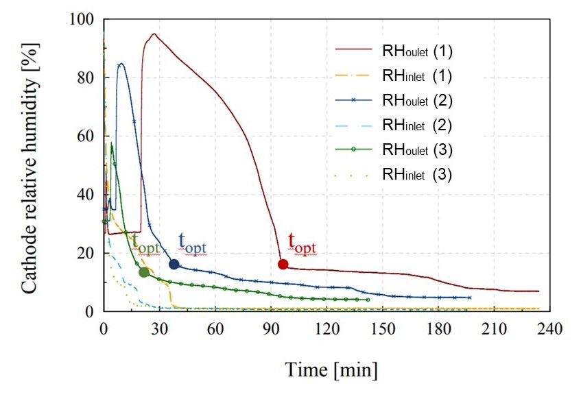
E3S Web of Conferences 334, 06004 (2022) https://doi.org/10.1051/e3sconf/202233406004
EFC21
Montaner Ríos et al., and hence not repeated here [9]. 2.2 Gas purging operating parameters
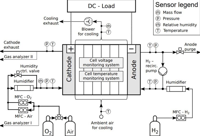
The test bench used with the 100 W stack was developed
in-house and is presented in Figure 1. The stack is fed This work studied experimentally the influence of the gas
with compressed air the cathode and with H2 the anode, purging operating parameters on the PEMFC system
whose mass flow rates are regulated: the cathode by two performance after cold storage, first with a 4 kW stack at
mass flow controllers (MFC) of 10 nl/min maximal flow temperatures down to -20°C, and next with a 100 W stack
rate, and the anode by one MFC of same maximal flow at temperatures down to -40°C. The selected parameters
rate. Both gases go through a humidifier before entering investigated with both stacks are given in Table 1.
into the stack. The relative humidity of cathode inlet is Additionally, F/T tests conducted with the 100 W stack at
regulated with a humidity control valve. The anode has a different purge times and cold storage temperatures are
hydrogen recirculation loop by a recirculation pump to listed in Table 2.
reuse the residual hydrogen and for humidification, and a
valve purge to regulate the pressure at anode side as well 2.3 Test protocol
as to remove accumulated water. A blower it is used for
cooling down the stack. Cell voltages are measured with Two experimental protocols were used in this
the cell voltage monitoring system (CVMS) and cell investigation, a different one for every kind of stack.
temperatures with the cell temperature monitoring system However, both protocols consist of six main steps:
(CTMS), which consists of six thermocouples connected conditioning, polarisation curve, gas purging procedure,
to the six bipolar plates of the five cells. Relative cold storage, start-up and polarisation curve again. The
humidity (RH) of cathode inlet and outlet are measured major difference between both protocols is that with the
with two relative humidity sensors, which produces 4 kW stack was carried out a cold start-up, while the
reliable values at RH < 90%. A load with a maximal start-up with the 100 W stack was carried out at room
power of 45 W is connected to the PEMFC. The control temperature. Furthermore, with the 100 W stack were
of system components and auxiliaries, such as: blower carried out two polarisation curves after the cold storage.
speed, cathode relative humidity and mass flow rates are Following, both experimental protocols are briefly
performed through a software developed in-house in described.
LAbVIEW. For the stack cold storage was used a
TT-60-375 U //logg FRYKA climate room of
2.3.1 Test protocol used with the 4 kW stack
(150 cm x 50 cm x 50 cm), which can freeze up to -45°C.
- Conditioning test at room temperature with dry gases,
but with humidification through H2 recirculation loop.
- Polarisation curve was carried out at room temperature
with dry gases, but with humidification through H2
recirculation loop, to get some reference points before
freezing temperatures and to guarantee the same relative
humidity level before purge procedure.
- Purge procedure. Stack purged with dry gases (at the
cathode N2, air or synthetic air, and at the anode H2) to
remove the remaining water before cold storage.
- Cold storage. The stack was further cooled down to the
testing temperature and kept for 4 h.
Fig. 1. PID of 100 W PEMFC system test bench.
Table 1. Operating parameters.
Parameter Value with the 4 kW stack Value with the 100 W stack
Cathode purge gas N2, air, synthetic air Air
Anode purge gas H2 H2
Purge temperature (°C) 15, 40, 50 25
Cathode purge flow rate (nl/min) 400 5, 10, 20
Anode purge flow rate (nl/min) 30 0.375, 0.75, 1.5
Purge time (s) 180 0, 45, 90, 300, 600, 1200, 3600, 8400, 12000, 14000
Cold storage temperature (°C) -20 -10, -20, -40
Cold storage time (h) 4 12
Start-up temperature (°C) -20 25
2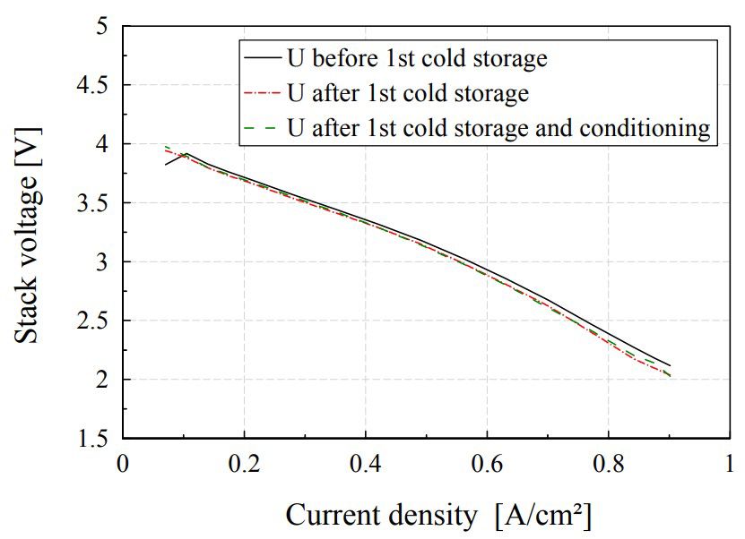
E3S Web of Conferences 334, 06004 (2022)                                                            https://doi.org/10.1051/e3sconf/202233406004
EFC21

                                               Table 2. F/T tests conducted with the 100 W stack.

             Test number (procedure)           1          2       3 (A)        4 (B)     5 (C)      6 (D)    7 (E)     8 (F)     9 (G)
          Cold storage temperature (°C)       -10        -20       -40         -40        -40       -40       -40       -40       -40
                  Purge time (s)             3600       3600      3600         1200      600        300       90        45         0

       - Cold start PEMFC. In order to get a quick cold start,               3.1.1 Cathode purge gas
       stack was run on potentiostatic mode and with a small
       cooling loop to warm it up quickly.                                   Tests were carried out purging the cathode before cooling
       - Polarisation curve was repeated to get same reference               down the stack at -20°C with different gas compositions:
       points, thus measuring the performance degradation due                synthetic     air     (O2 20.9 Vol.-%,      N2 79.1 Vol.-%),
       to the freezing temperatures.                                         compressed air and pure nitrogen. During cold storage
                                                                             stack is soaked with dry gases which can diffuse form
       2.3.2 Test protocol used with the 100 W stack                         cathode to anode, and vice versa (fuel and oxidant
                                                                             crossover). Thus, purging the cathode with air may lead
       - Conditioning test at room temperature with wet gases.               to an air-hydrogen front that could cause material and
       - Polarisation curve at room temperature with wet gases.              performance degradation [4]. However, by comparing
       - Purge procedure. Stack was purged with dry gases (at                polarization curves was found neither any difference
       the cathode air and at the anode H2). For that, humidifier            between different gases used, nor performance
       is set to a relative humidity of 0%. During the purge                 degradation. Therefore, and for technical reasons
       procedure, the cathode outlet RH sensor was plugged into              compressed air was defined as purge cathode gas for next
       the system, when the cathode inlet RH was 10%, to avoid               tests as well as for the later study with the 100 W stack.
       that remaining water in the cathode outlet could condense
       at the top of the RH sensor, thus falsifying the test results.        3.1.2 Purge temperature
       - Cold storage. The stack was stored in the climate room
       to the testing temperature and kept there for 12 h.                   The purge temperature has an effect on the amount of
       - Polarisation curve was carried out at room temperature              water removed: a higher temperature can be beneficial to
       and with wet gases to measure the performance                         take off more water, but the contrary would result from
       degradation due to the freezing temperatures.                         too high temperature [8, 12]. Test results of varying
       - Conditioning test at room temperature with wet gases.               purge temperature from +15°C to +50°C didn’t show any
       Since the conditioning test is a procedure that can                   relevant influence, neither on the 4 kW PEMFC system
       overcome reversible degradation, this test was repeated               performance degradation after cold storage nor on its cold
       before carrying out other polarization curve, to prove                start ability. But purging with a high-power size stack at
       which performance degradation due to the cold storage                 high temperatures (e.g. +85°C) may result in a non-
       was reversible.                                                       uniform drying, thus potential membrane damage [4, 12].
       - Polarisation curve at room temperature with wet gases.              For this reason, and in order to increase the energy
                                                                             efficiency of the system by eliminating the energy
                                                                             consumed by gas heaters, the purge procedure in the next
       3 Results                                                             study with the 100 W stack was carried out at +25°C.

       3.1 Cold storage with the 4 kW stack                                  3.1.3 Purge time

       This investigation is partly based on prior studies of the            The purge time influences the water remaining in the
       purge time influence on the cold start of this 4 kW stack             stack membranes. These experimental results showed,
       [10, 11]. Experimental results showed that the optimal                that the purge time influence on the cold start time of the
       purge time for slow cold starts was an intermediate value,            PEMFC system was lower for quick cold starts than for
       so that membranes can absorb large amounts of water                   the slow ones. Moreover, no performance degradation
       instead of freezing in the cathode catalyst layer (CCL),              was measured after more than 70 cold starts by purging
       while being hydrated to guarantee proton conductivity                 for 3 min (intermediate-low value) 400 nl/min of air in
       during the cold start [10]. Additionally, a 1-cell cold start         the cathode and 30 nl/min of H2 in the anode before
       model was developed which calculates the ice fraction                 freezing the stack at -20°C, while parasitic loses during
       during cold start at temperatures down to -40°C and was               shut-down were a bit lower.
       used to study the influence of the purge time on its cold
       start ability [11]. These simulation results validated the            3.2 Cold storage with the 100 W stack
       obtained experimentally.
           In this study the influence of the cathode purge gas,
                                                                             3.2.1 Purge gases flow rates
       the purge temperature and the purge time on the PEMFC
       system performance after cold storage at -20°C were                   Purge gases volume flow rates and optimal purge time
       further investigated with the 4 kW PEMFC system,                      (intermediate-low value) previously selected for the 4 kW
       whose experimental results can be summarized as                       stack have been taken as reference to calculate the purge
       follows.                                                              gases flow rates and time for the 100 W stack, even

                                                                         3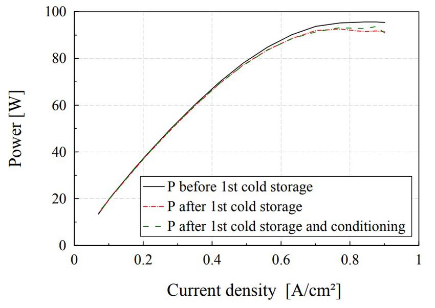
E3S Web of Conferences 334, 06004 (2022)                                                             https://doi.org/10.1051/e3sconf/202233406004
EFC21

       though both stacks have different power sizes and fuel                 3.2.2 Cold storage temperature and purge time
       cell components, hence different water storage capacities.
       According to this estimation, the 100 W stack should be                To illuminate the impact of the cold storage and purge
       purged before freezing at -20°C for 90 s with air in the               time on the performance degradation of a PEMFC system
       cathode at 20 nl/min and with H2 in the anode at                       due to cold storage at temperatures down to -40°C,
       1.5 nl/min. Therefore, in this study the cathode flow rate             nine F/T cycles listed in Table 2 were conducted with
       by purging was varied between 5 and 20 nl/min, as the                  different cold storage temperatures and purge times.
       cathode MFCs maximal flow rate is 10 nl/min, and hence                     Figure 3 illustrates the effect of the first cold storage
       the anode flow rate between 0.375 and 1.5 nl/min.                      (test number 1 of Table 2) on the stack performance
           Figure 2 presents the evolution over time of the                   degradation by comparing the voltage (Fig. 3(a)) and the
       cathode relative humidities inlet and outlet (RH) at                   power density (Fig. 3(b)) as a function of current density
       different purge gases flow rates. As Figure 2 shows,                   before and after the first F/T cycle, as well as after a later
       cathode outlet relative humidity decreases proportionally              conditioning test.
       as the flow rate increases, thought this decrease is not                   (a)
       linear. Indeed, cathode relative humidities decreased
       much faster with cathode purge volume flow rates equal
       to or higher than 10 nl/min. Since the cathode outlet was
       dried faster by purging with air in the cathode at
       20 nl/min and with H2 in the anode at 1.5 nl/min, this
       combination was selected for next series of tests.
       Moreover, and based on the previous results with the
       4 kW stack, we suppose that the optimal purge time (topt)
       for the 100 W stack is not bigger than the corresponding
       time of the turning point, in which the cathode outlet RH
       begins to decrease slowly. For the 100 W stack this RH
       value was below 20% for all purge gas combinations, as                     (b)
       illustrated in Figure 2. We assume that at this point no
       relevant water was remaining neither in the channels, nor
       in the gas diffusion layers (GDL), and that most of the
       water remaining in the cells is in a non-freezable state at
       the cold storage temperatures. So, purge times longer
       than topt are not necessary to assure no severe damages
       due to ice-formation during the cold storage. Moreover,
       by reducing parasitic losses of a very long purging. the
       energy efficiency of the system increases. To the
       contrary, the purge time should be long enough, so that
       no relevant water remains in the system that can turn into
       ice, thus damaging the stack and/or other components.
       Therefore, we expect that the minimal purge time should                Fig. 3. Effect of the first cold storage at -10°C on the 100 W
       be the turning point in which the cathode inlet RH begins              stack performance: (a) polarization curves; (b) p-j curves.
       to decrease slowly. These assumptions were studied in
       the next series of tests.                                                  As Figure 3 shows, the stack already experienced
                                                                              irreversible performance degradation after the first cold
                                                                              storage, even though it was at a not very low temperature
                                                                              (-10°C). This degradation may have occurred due to the
                                                                              ice formation during cold storage, but it might be most
                                                                              likely due to the long purging procedure carried out (1 h).
                                                                              This performance losses may be caused mainly by two
                                                                              factors; the large period at open circuit voltage (OCV)
                                                                              during the purge procedure, and by the excessive dryness
                                                                              of the cells, which may cause an uneven stress
                                                                              distribution in the membrane, thus resulting in membrane
                                                                              degradation [4, 12]. By operating the stack at OCV can
                                                                              cause fuel and oxidant crossovers as well as cells
                                                                              reversal, which would lead to a higher CO2-corrosion,
                                                                              thus degrading the cells irreversibly [13-15].
                                                                                  Figure 4 compares the polarization and power density
       Fig. 2. Cathode relative humidities (inlet and outlet) over time
                                                                              curves of the 100 W stack before and after F/T cycles
       during purge procedure for different combination of gases
       volume flow rates: (1) 5 nl/min of air and 0.375 nl/min of H2,         from Table 2 at different purge times and cold storage
       (2) 10 nl/min of air and 0.75 nl/min of H2, and (3) 20 nl/min of       temperatures. Specifically, from before the 1st cold
       air and 1.5 nl/min of H2.                                              storage at -10°C after purging 1 h, to after the 7th cold
                                                                              storage at -40°C after purging 90 s.

                                                                          4
E3S Web of Conferences 334, 06004 (2022)                                                              https://doi.org/10.1051/e3sconf/202233406004
EFC21

       (a)                                                                    4. Conclusions
                                                                              In this investigation, the impact of the purge procedure
                                                                              and the cold storage on the performance of two types of
                                                                              PEMFC fuel cell systems has been studied. The main
                                                                              findings of this experimental work are addressed below.
                                                                                  Results showed that the purge temperature required
                                                                              didn’t seem to be necessary at a high temperature.
                                                                              Indeed, a higher temperature may lead to a non-uniform
                                                                              drying, thus accelerating membrane degradation [4, 12].
                                                                              Hence, this temperature was chosen according to the
                                                                              system at room temperature, thus reducing parasitic
       (b)                                                                    losses and consequently enhancing the energy efficiency
                                                                              of the system.
                                                                                  Purge shutdown procedure has to be chosen very
                                                                              carefully. This study has shown that very long purging
                                                                              (e.g. more than 20 min for the 100 W stack) also lead to
                                                                              degradation, even at not very low temperatures, such as
                                                                              -10°C. This degradation may have occurred because of
                                                                              the large period at OCV and by the excessive dryness of
                                                                              the cells. Besides, a purging procedure that dries the cells
                                                                              completely would be extremely slow and energy
                                                                              inefficient because of the parasitic losses. Therefore, the
                                                                              optimal purge time is the one reducing remained water in
       Fig. 4. Effect of the F/T cycles from Table 2 on the 100 W stack       the cells to a value below that at which damage occurs,
       performance: (a) polarization curves; (b) p-j curves.                  but not too long to avoid membrane degradation due to
                                                                              internal stress generation. For the 100 W stack, the
           As Figure 4 illustrates, the greatest performance                  optimal purge time was found to be between 1.5 min and
       losses result from the firsts cold storages at -10°C and at            10 min by purging 20 nl/min air at the cathode and
       -40°C, which both have the longest purging procedure                   1.5 nl/min of H2 at the anode. This is in relation with the
       (1 h). This indicates that the performance losses are likely           results obtained with the 4 kW stack.
       to be influenced more by the long purging than to the                      Very long purging procedures with air at the cathode
       freezing temperatures. Therefore, a purge time between                 and H2 at the anode led to degradation, which may be
       1.5 and 10 min seems to be more adequate for the 100 W                 caused due to fuel and oxidant crossover. For this reason
       stack, since a shorter purging reduces degradation and                 and to enhance the safety and fuel cell efficiency of the
       parasitic losses. Thus, the durability and energy                      system, eliminating anode purge or drying it with
       efficiency of the PEMFC system can be increased. These                 nitrogen should be consider.
       results validate our previous assumption of optimal purge                  In addition, the use of a microporous layer (MPL),
       time (section 3.2.1.), and are in agreement with the                   material choice, cell components design (e.g. diffusion
       results obtained for the 4 kW stack, in which the optimal              media thickness or channel/land) and the use of a
       purge time was defined as 3 min (400 nl/min air at the                 methanol solution as antifreeze during cold storage can
       cathode, 30 nl/min H2 at the anode). Moreover, and                     help to mitigate degradation due to ice formation
       according to Figure 2, after purging 10 min the 100 W                  [4, 16, 17, 18]. With the aim of reducing the degradation
       stack (20 nl/min air at the cathode, 1.5 nl/min H2 at the              due to subfreezing temperatures of a PEMFC system for
       anode), the cathode outlet relative humidity was                       aircraft applications, these findings will be validated with
       approximately 20%. Which is also in concordance with                   a state-of-the-art stack, for which cold storages down to
       the experimental results obtained by St-Pierre et al. [12].            -40°C will be carried out. The design of this state-of-the-
           By comparing performance curves before and after a                 art stack together with the purge procedure are expected
       F/T cycle at -40°C without purging (test 9(G) from                     to reduce degradation due to ice-formation during cold
       Table 2), performance losses due to ice formation were                 storage.
       observed, specially at current densities higher than
       0.75 A/cm². These losses were mostly irreversible, not
       being recovered even after some conditioning tests. But                This work was financially supported by the Federal Ministry of
                                                                              Transport and Digital Infrastructure of Germany within the
       these losses were lower than expected. A possible reason               framework of the BILBO project (No 03B10701C) and, by the
       for that may be that the stack operated with an excess                 Fuel Cells and Hydrogen 2 Joint Undertaking within the
       oxygen ratio of 3 at low current densities (lower than                 framework of the INN-Balance project (No 735969). This Joint
       0.1 A/cm²) for the last twenty minutes of the polarization             Undertaking receives support from the European Union’s
       curve. Therefore, the stack was already partly dried                   Horizon 2020 research and innovation programme, Hydrogen
       before freezing without conducting any purge procedure.                Europe and Hydrogen Europe research. The authors would like
       This shows, that combining the purge procedure with the                to thank Stefan Bleeck and Vincent Hackstein for the set up
       previous operation of the PEMFC system would be                        hardware and software of the 100 W fuel cell test bench, as well
       optimal to reduce time and energy consumption.                         as Dr. Johannes Schirmer for fruitful discussions.

                                                                          5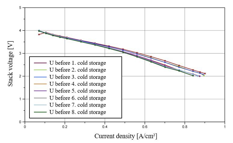
E3S Web of Conferences 334, 06004 (2022)                                                      https://doi.org/10.1051/e3sconf/202233406004
EFC21

       References                                                       11. M Schröder, C Gentner, G Montaner Ríos, F Becker,
                                                                            S Bleeck, I Sokolov, J Kallo, MODVAL (2019)
       1.  https://www.iea.org/                                         12. J St-Pierre, J Roberts, K Colbow, et al., J. New Mater.
       2.  D S Lee, et al., Atmos. Environ. 244, 117834 (2021)              Electrochem. Syst. 8, 163 (2005)
       3.  H Webber, S Job. (2021). https://www.ati.org.uk/             13. P Reng, P Pei, Y Li, Z Wu, D Chen, S Huang. Prog.
       4.  M M Mench, E C Kumbar, T N Veziroglu, Polymer                    Energy Combust. Sci. 80, 100859 (2020)
           electrolyte fuel cell degradation, (Elservier, Oxford;       14. N Dyanti, A Parsons, P Bujlo, S Pasupathi, Mater
           2012)                                                            Renew Sustain Energy. 8, 4 (2019)
       5. E Pinton, L Antoni, Y Fourneron, S Rosini, ECS                15. S Kundu, M Fowler, L Simon, R Abouatallah, N
           Trans. 17, 251 (2009)                                            Beydokhti, J Power Sources. 183, 619 (2008)
       6. S-Y Lee, et al., J Power Sources. 180, 784 (2008)             16. A Turhan, K Heller, J S Brenizer, M M Mench, J
       7. S Kim, C Chacko, R Ramasamy, M M Mench, ECS                       Power Sources. 180, 773 (2008)
           Trans. 11, 577 (2007)                                        17. F Knorr, D Garcia Sanchez, J Schirmer, P Gazdizcki,
       8. P Xu, S Xu, SAE Int. 01,1312 (2018)                               K A Friedrich, Appl. Energy. 238, 1 (2019)
       9. G Montaner Ríos, J Schirmer, C Gentner, J Kallo,              18. G Montaner Ríos, J Schirmer, F Becker, S Bleeck, C
           Appl. Energy. 279, 115813 (2020)                                 Gentner, J Kallo, ECS Trans. 98, 243 (2020)
       10. G Montaner Ríos G, J Schirmer, J Kallo, EFC (2017)

                                                                    6
You can also read