Towards Restoring Locomotion for Paraplegics: Realizing Dynamically Stable Walking on Exoskeletons
←
→
Page content transcription
If your browser does not render page correctly, please read the page content below
2018 IEEE International Conference on Robotics and Automation (ICRA)
May 21-25, 2018, Brisbane, Australia

                Towards Restoring Locomotion for Paraplegics:
             Realizing Dynamically Stable Walking on Exoskeletons
      Thomas Gurriet1 , Sylvain Finet2 , Guilhem Boeris2 , Alexis Duburcq2 , Ayonga Hereid3 , Omar Harib3 ,
                            Matthieu Masselin2 , Jessy Grizzle3 and Aaron D. Ames1

   Abstract—This paper presents the first experimental results
of crutch-less dynamic walking with paraplegics on a lower-
body exoskeleton: ATALANTE, designed by the French start-up
company Wandercraft. The methodology used to achieve these
results is based on the partial hybrid zero dynamics (PHZD)
framework for formally generating stable walking gaits. A direct
collocation optimization formulation is used to provide fast and
efficient generation of gaits tailored to each patient. These gaits
are then implemented on the exoskeleton for three paraplegics.
The end result is dynamically stable walking in an exoskeleton
without the need for crutches. After a short period of tuning
by the engineers and practice by the subjects, each subject was
able to dynamically walk across a room of about 10 m up to a
speed of 0.15 m/s (0.5 km/h) without the need for crutches or
any other kind of assistance.

                        I. I NTRODUCTION
   Regaining autonomy in their daily lives through the ability
to walk again is a central aspiration for many people with
lower limb paralysis, i.e. paraplegics. Among the promising
solutions to restore locomotion are robotic devices that fit
around the legs of a user, called lower-limb exoskeletons for
rehabilitation. A comprehensive review of the state-of-the-
art lower-limb exoskeletons can be found in [10]. Research
in this field began in the early 1960s independently at the
Mihailo Pupin Institute in Belgrade [18], [26] and at the Uni-
versity of Wisconsin [15], [24]. The resulting exoskeletons
were able to physically advance the legs of a user, but the                Fig. 1: Image of two paraplegic patients walking in the
user had to use crutches to maintain balance. Additionally,                ATALANTE exoskeleton developed by Wandercraft.
there has been a broad body of work on different aspect of
exoskeletons [10], [25], [29] from assistive knee devices [11]             use in rehabilitation centers. Nevertheless, these exoskeletons
to soft exoskeletons [27]. Throughout the years, in addition to            still have very limited capabilities: either they require the use
regaining autonomy, clinical tests showed the health benefits               of crutches for balance or direction control, which is tiring
of walking for paraplegics: improvement of blood circulation,              for the user [1], [2], or they provide slow static gaits with
of respiratory, urinary, and intestinal functions, and positive            velocities on the order of 0.05 m/s [3]. The ultimate goal
psychological effects [20].                                                is to have a device that provides fast, robust and dynamic
   Due to the physical and psychological advantages of                     gaits for safe daily use anywhere. By ”dynamic”, as opposed
exoskeletons, multiple companies have emerged over the past                to ”static”, we mean that the high level control goal is to
decade and have started to commercialize their products for                stabilize periodic motions that do not necessarily keep the
                                                                           center of mass (or even of center of pressure) within a
   *This work has been conducted under IRB No. 16-0693.                    support polygon of the feet. From an outside perspective,
   1 Thomas Gurriet and Aaron Ames are with the Department of Mechanical
and Civil Engineering, California Institute of Technology, Pasadena, CA    during a step the exoskeleton is falling forward only to
91125. Their work was supported by NSF NRI award 1526519.                  have the swing foot reach out and catch the user before
   2 Matthieu Masselin, Sylvain Finet, Guilhem Boeris and Alexis Duburcq
                                                                           beginning the process again. This is the behavior naturally
are with Wandercraft, Paris, France.
   3 Ayonga Hereid, Omar Harib and Jessy Grizzle are with the Department   achieved by humans when they walk, and the objective is
of Electrical Engineering and Computer Science, Univ. of Michigan, Ann     thus to endow exoskeletons with these behaviors. The French
Arbor, MI 48109. The work of A. Hereid was supported by NSF under          start-up company Wandercraft has emerged with the goal of
Grant CPS-1239037. The work of J. W. Grizzle was partially supported by
a gift from Ford Motor Company.
                                                                           designing such devices [5].

978-1-5386-3081-5/18/$31.00 ©2018 IEEE                                 2804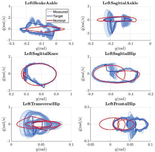
Hybrid System Model                           Gait Optimization                         Simulations

                   +                                                                            Nominal trajectory
                                                                                                   generation
               Model data
                                                                                                  Gait Tunning
                         Hybrid System

        Domain graph                                                                       Stable Dynamic Walking

 Fig. 2: The methodology developed that yielded dynamically stable exoskeleton walking experimentally for paraplegics.

   Recent progress in the field of robotic bipedal locomotion,       report of any sort. Therefore, the contributions of this paper
both in terms of hardware development and control algorithm         are:
design, is making dynamic locomotion on exoskeletons a                 • The application of the PHZD method to the experimental
possibility. Of particular note for this work is the the method          control of a lower-limb exoskeleton.
of virtual constraints and hybrid zero dynamics (HZD method            • The realization of dynamically stable walking for para-
for short) which has resulted in dynamic walking on multiple             plegics without the use of crutches or any other kind of
robots by facilitating the design of gaits that are provably sta-        assistance.
ble and experimentally realizable; they enforce the unilateral         The remainder of the paper is organized as follows (fol-
ground contact as well as friction and input torque bounds          lowing the methodology in Fig. 2). Section II presents a
[8], [12], [13], [17], [28]. Virtual constraints are relations      hybrid model of the human exoskeleton system and the
between the joints or links of a device that are induced by         PHZD framework. This leads to our framework for the design
feedback control instead of a physical connection. They thus        of stable dynamic walking gaits represented as a nonlinear
induce a reduced-order dynamic model of the hybrid system           optimization problem under constraints. The resolution of this
that is called the hybrid zero dynamics. The method of HZD          problem using direct collocation is described in Section III.
was extended to allow for multi-contact walking for robots          Finally, Section IV presents the implementation of the gaits
with feet in the context of partial hybrid zero dynamics, or        on the exoskeleton and the experimental results.
PHZD for short [7]. PHZD has been successfully realized
to achieve dynamic and efficient locomotion on humanoid                          II. M ATHEMATICAL F OUNDATION
robots with feet [17], [22], [23] and, as a result, is a natural       In this section, we summarize our approach for gen-
framework in which to control exoskeletons with the goal of         erating stabilizing controllers for the powered lower-limb
dynamic and human-like gaits. Quite recently, preliminary           exoskeleton ATALANTE by building upon the (PHZD)-
simulation results showed the application of PHZD to the            based theoretical foundation [7]. More precisely, we utilize
control of an exoskeleton worn by a paraplegic; see [6] for         the hybrid nature of bipedal locomotion and implement
details as well as later in the paper.                              stable periodic behaviors by enforcing invariant reduced
   Wandercraft has designed an exoskeleton, named ATA-              dimensional manifolds via virtual-constraint-based feedback
LANTE, which has realized for the first time, using con-             controllers. Because in these experiments, the user is not yet
trollers based on the PHZD method, dynamic stable walking           able to use his or her upper body to select the speed of
for paraplegics without the use of crutches or any other kind       the gait, the presentation does not require the decentralized
of assistance (as illustrated in Fig. 1). This paper describes      implementation presented in [6].
the formal foundations along with the methodology used
for achieving this performance and presents some promising          A. Hybrid System Model
experimental results: after a short period of tuning by on-           ATALANTE is a lower-limb exoskeleton designed by the
site engineers and practice by the subjects, each subject was       French startup company Wandercraft. It is intended to be used
able to dynamically walk across a room of about 10 m up to          by paraplegics in medical center settings for rehabilitation.
a speed of 0.15 m/s (0.5 km/h). Although it reports results         The exoskeleton has 12 degrees of freedom (6 per leg).
obtained with patients in clinical settings, it is not a clinical   Except for the ankle, where a special mechanism is mounted,
                                                                2805
exoskeleton system as a hybrid control system (see [6] for
                                                                         full definition):
                                                                                           H C = {D, U , S, Δ, FG},                    (2)
                                                                         where D ⊆ T Q is a smooth manifold representing the
                                                                         admissible domain of the states, U is the admissible control
                                                                         inputs, S ⊂ D is a switching surface, Δ is the reset map of
                                                                         the discontinuous dynamics, and FG is the control system
                                                                         defined on the continuous domain. The definition of each
                                                                         element of (2) is discussed briefly below.
                                                                         Continuous Dynamics. For flat-footed walking, the contin-
                                                                         uous domain D is determined by the planar contact of the
                                                                         stance foot with the ground. Assuming the ground is rigid, we
 (a) Human Exoskeleton Model            (b) Kinematic Tree
                                                                         will use holonomic constraints to model the contact, i.e., the
Fig. 3: Kinematic diagram of the human exoskeleton system.               position and the orientation of the stance foot link remain
The green links in (b) are adjustable in length.                         constant during the course of one step. Let μ(q) ∈ R6 be
                                                                         the collection of stance foot position and orientation, the
each degree of freedom is independently actuated by a brush-             kinematic constraint of the foot contact is J(q)q̇ = 0, where
less DC motor. A digital encoder is mounted on each motor
                                                                         J(q) = ∂ μ(q)
                                                                                   ∂ q is the Jacobian of holonomic constraints.
to estimate joint position and velocity. Sensors installed in
                                                                            Given the mass, inertia, and length properties of each link
the feet allow for impact detection when the feet hit the
                                                                         of the human exoskeleton system, the equation of motion
ground. The exoskeleton is controlled by a central computer
                                                                         (EOM) of the continuous dynamics is then determined by the
board running a real-time operating system and in charge of
                                                                         classical Euler-Lagrange equation and holonomic constraints
all high-level computations. The dimensions of ATALANTE
                                                                         of the domain [14], [21]:
can be easily adjusted to fit the patient through mechanical
adjustments. The patient is secured to the exoskeleton by                               D(q)q̈ + H(q, q̇) = Bu + J T (q)F              (3)
means of fasteners located at the ankle, the shin, the thigh,
and the abdomen. ATALANTE is self-powered with a battery                 where D(q) is the inertia matrix, H(q, q̇) = C(q, q̇)q̇ + G(q)
pack.                                                                    is the vector containing the Coriolis and gravity term, B is
                                                                         the actuator distribution matrix, u ∈ U ⊆ R12 is the actuator
   One key assumption in the current paper1 is that the user’s
                                                                         inputs vector. The contact wrenches, F, can be calculated
legs are rigidly attached to the exoskeleton and there is no
                                                                         by solving the second order derivative of the holonomic
actuation from the human body. The upper human body is
                                                                         constraints,
modeled as a single rigid link—ignoring the relative motion
of the waist, neck and arm joints of the human—rigidly                                        J(q)q̈ + J(q,
                                                                                                        ˙ q̇)q̇ = 0,                   (4)
attached to the pelvis of the exoskeleton. The lumped human-
exoskeleton system then can be modeled as a kinematic tree               and (3) simultaneously. Substituting the closed form solution
of rigid links, as shown in Fig. 3. Specifically, we use floating          of F yields the affine control system, FG, given as,
base coordinates: assuming Rb is a body-fixed reference                                          ẋ = f (x) + g(x)u,                    (5)
frame of the pelvis link with Cartesian position p ∈ R3 and
orientation φ ∈ SO(3) with respect to the world frame R0 ,               with x = (q, q̇) ∈ D being the state of the system.
the configuration coordinates, Q, of the system, given as                 Discrete Dynamics. When the swing foot hits the ground,
                                                                         an instantaneous change in contact occurs. We denote the
            q = (p, φ , qb ) ∈ Q = R3 × SO(3) × Qb ,              (1)    triggering condition of the event as a guard S ⊂ D. Moreover,
                                                                         we assume that the impact with the ground is perfectly
                                                                         plastic. As a consequence, the joint configuration remains the
represents the generalized coordinates of the system. The
                                                                         same during impact, but the joint velocities undergo a discrete
body coordinates, qb ∈ Qb , represent the 12 actuated lower-
                                                                         change. More precisely, using the derivation proposed by
limb exoskeleton joints—each leg consists of 3 hip joints, 1
                                                                         Hurmuzlu et al. [19], we get:
knee joint, and 2 ankle joints.
   The dynamic behavior of bipedal locomotion is often                      q̇+ = I − D−1 (q+ )J T (q+ )Ξ(q+ )J(q+ ) q̇− := Δq̇ (q)q̇− ,
characterized as a hybrid system consisting of a series of                                                                              (6)
continuous phases (e.g., when the leg swings forward) and
                                                                         where, for simplicity, Ξ(q) = (J(q)D−1 (q)J T (q))−1 . This
discrete events (e.g. when the foot strikes the ground) [14].
                                                                         discrete dynamics of the system can be captured as a reset
In particular, we model the walking behavior of the human
                                                                         map, Δ, that maps the pre-impact states to post-impact states:

                                                                                      + +          − −              q−
  1 In [6] we allow the user to control the exoskeleton via upper body              (q , q̇ ) = Δ(q , q̇ ) :=                .      (7)
posture; hence an articulated model of a human is used.                                                         Δq̇ (q)q̇−

                                                                     2806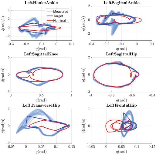
which is invertible due to the specific choice of virtual
                                                                        constraints. Applying this control law to (5) yields linear
                                                                        output dynamics of the form:
                                                                                               ẏ1 = −εy1 ,                          (13)
                                                                                               ÿ2 = −2ε ẏ2 − ε y2 .
                                                                                                                2
                                                                                                                                     (14)
  (a) Periodic Orbit                 (b) Hybrid Invariance
                                                                          Under the control law, the system in (5) renders an invari-
Fig. 4: Illustration of the hybrid invariant periodic orbit on
                                                                        ant reduced dimensional surface, termed as zero dynamics
the partial hybrid zero dynamics (PHZD) surface. A PHZD
                                                                        [28]:
surface is constructed via choosing the proper parameters set
α through optimization.                                                      Zα = {(q, q̇) ∈ D|y1 (q, q̇, α) = 0,
   Moreover, applying the feedback controllers to the hybrid                                   y2 (q, α) = 0, ẏ2 (q, q̇, α) = 0}.   (15)
control system given in (2) yields a hybrid system model,               Since the velocity q̇ undergoes a jump at impact (6), and vd
given as                                                                is a constant, then the output y1 necessarily undergoes a jump
                        H = (D, S, Δ, F).                        (8)    (see (9)), and the zero dynamics surface cannot be invariant
                                                                        through impact. Thus, we prefer to ignore this output and
with U = 0. / In the next section, we introduce virtual con-            consider the following partial zero dynamics surface, given
straints as a means to synthesize feedback controllers that             by:
realize stable walking of the human exoskeleton system.
                                                                           PZ α = {(q, q̇) ∈ D|y2 (q, α) = 0, ẏ2 (q, q̇, α) = 0}.   (16)
B. Partial Hybrid Zero Dynamics
    At the core of our controller approach is designing a               It is straightforward to show that the control law in (11)
set of virtual constraints that modulate the system behavior            renders the partial zero dynamics submanifold invariant, i.e.,
in order to achieve certain desired trajectories [7], [28].             any solution that starts in PZ α remains in PZ α until
Enforcing virtual constraints results in a reduced dimensional          reaching a guard [7]. However, it is not necessarily invariant
representation of the full order system that captures the               through impacts. To this end, the set of parameters α is
natural dynamics of the robot.                                          constrained to be such that the partial zero dynamics is
                                                                        invariant through impacts. There exists a set of parameters α
Virtual Constraints. For the particular case of the human
                                                                        so that the submanifold PZ α is impact invariant if
exoskeleton system with actuated ankle joints, we choose the
actual outputs to be a combination of velocity regulating term                               Δ(S ∩ PZ α ) ∈ PZ α                     (17)
ya1 and position modulating terms ya2 . Specifically, the velocity
regulating term is chosen to be the forward hip velocity with a         A manifold PZ α is called hybrid invariant if it is invariant
constant desired velocity vd , and position modulating outputs          through impacts, and thus the hybrid system in (8) has a
are chosen to represent the synchronized motion of the rest             partial hybrid zero dynamics (PHZD), denoted as H |PZ α .
of the mechanical system. The virtual constraints are defined            By enforcing partial hybrid zero dynamics, the full order
as the difference between the actual and desired outputs:               dynamics of the hybrid system can be captured in a reduced-
                                                                        dimension dynamical system that is independent of control
               y1 (q, q̇, α) = ya1 (q, q̇) − vd ,                (9)    inputs. Finding such parameters is typically formulated as a
                  y2 (q, α) =   ya2 (q) − yd2 (τ(q), α),        (10)    nonlinear constrained optimization problem [7], [17].
where y1 and y2 are relative degree 1 and (vector) relative             Theorem 1. If the hybrid system H in (8) satisfies (17),
degree 2 by definition, yd2 is a vector of desired trajectories. In      then there exists ε > 0 such that for all ε > ε the feedback
this paper, we use Bézier polynomials to represent the desired         controller (11) yields a periodic orbit O = ι0 (OPZ ), for
outputs with α being a set of Bézier coefficients, and τ(q)             OPZ ⊂ PZ α and ι0 : PZ α → D the canonical embedding,
the state-based timing variable for synchronization [6].                that is a locally exponentially stable periodic orbit of H .
Feedback Linearization. With the goal of driving the virtual               Importantly, this theorem implies that the robot represented
constraints in (9) and (10) to zero exponentially, we use the           by the hybrid system H has an exponentially stable walking
following feedback control law,                                         gait. Space constraints do not allow for a proof of this result,

      α,ε       −1                0                                     but it follows in a straightforward manner from the results of
    u =−A
                         L2f y2 (q, q̇, α)                              [7].

                   L f y1 (q, q̇)            εy1 (q, q̇, α)             Remark 1. Introducing partial zero dynamics not only allows
            +                           +                      , (11)
                2εL f y2 (q, q̇, α)          ε 2 y2 (q, α)              us to command a constant desired velocity, but also the
with a control gain ε > 0 and decoupling matrix                         evolution of y1 is now solely determined via the linear output
                                                                      dynamics given in (13) and is independent of τ. This allows
                            Lg ya1 (q, q̇)                              for a driving element that pushes the robot forward regardless
                 A =                            ,               (12)
                         Lg L f y2 (q, q̇, α)                           of the state of the phase variable.
                                                                    2807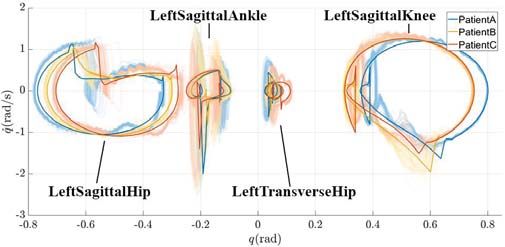
III. G AIT G ENERATION AND S IMULATIONS
   Using the PHZD framework described above, we want to
design the desired profile of the virtual constraints that when
enforced leads to a stable walking gait. This is done through
a nonlinear constrained optimization process using direct
collocation. Others ways of solving the optimization can be
used like single shooting methods, but direct collocation was
found to be the fastest and most efficient way to solve this
problem [17]; stable walking gaits are obtained in minutes. In
this section we presents an overview of how we used direct
collocation to obtain stable dynamic walking gaits.

A. Direct Collocation Optimization
   Direct collocation methods have been widely used for
trajectory optimization of dynamical systems governed by
ordinary differential equations [9], [16]. In this work, we in-
corporated the virtual constraints based feedback controller in                      Fig. 5: Simulation of the gait for the exoskeleton with a
the direct collocation based trajectory optimization problem.                        dummy inside.
The PHZD constraint in (17) is enforced at impact, such that                         For detailed setup of the optimization problem, we refer the
the optimized trajectory is a hybrid invariant periodic orbit.                       readers to [6].
The end result is a set of parameters α for a stable walking                            In this work, we state the direct collocation based human
gait.                                                                                exoskeleton gait optimization to minimize the mechanical
   The mathematical foundation of the direct collocation                             cost of Transport (CoT), ΦCoT , of the gait, i.e.,
optimization is based on the finite step implicit Runge-Kutta
methods [9]. Specifically, we divide the continuous dynamics                                            argmin ΦCoT (z)                          (21)
solution into a fixed number of intervals. Let                                                             z∗
                                                                                                         s.t zmin ≤ z ≤ zmax ,                  (22)
                 0 = t0 < t1 < t2 < · · · < tN = TI ,                         (18)
                                                                                                               cmin ≤ c(z) ≤ cmax ,             (23)
be the discrete time instances, a.k.a., nodes, defined at the
                                                                                     where z is the set of all decision variables, and c(z) is a
terminal of these intervals, where TI > 0 is the time at
                                                                                     collection of necessary constraints presented in [17]. Torque
which the swing foot hits the ground. Also, we introduce
                                                                                     limits and joint position and velocity limits of the ATA-
xi , ẋi , ui , and F i as decision variables of the optimization
                                                                                     LANTE are directly enforced as boundary conditions of
problem to approximate the state variables, control inputs,
                                                                                     decision variables in (22), whereas friction cone and zero
ground reaction forces of the system at node i, and introduce
                                                                                     moment constraints of the foot contacts are enforced as
α ∗ as decision variables for the virtual constraints param-
                                                                                     extra physical constraints. In addition, several constraints are
eters, respectively. Next, we modify the classical Hermite-
                                                                                     considered in the optimization in order to narrow down the
Simpson method over time intervals between two neighboring
                                                                                     search space and address certain aspects specific to human-
even nodes. Specifically, the following equality constraints—
                                                                                     friendly walking. Impact velocities, ZMP position, CoM
termed as defect constraints—are enforced:
                                                                                     position and torso orientation are an example of the many
     ẋi − 3(xi+1 − xi−1 )/2Δt i + (ẋi−1 + ẋi+1 )/4 = 0,                    (19)   constraints that need to be considered.
        i       i+1        i−1            i     i−1          i+1                        A challenge arises here, as each patient has a specific mass
       x − (x         +x         )/2 − Δt (ẋ         − ẋ         )/8 = 0,   (20)
                                                                                     distribution and dimensions which lead to unique dynamics
for all i ∈ {1, 3, · · · , N − 1}, where Δt i = ti+1 − ti−1 is the                   for each individual. In order to accelerate this process, Wan-
time interval. If the Lagrangian dynamics in (3) and holo-                           dercraft has derived a fast way to recompute the dynamics for
nomic constraints in (4) are satisfied at each node, then the                         each case, making it possible to rapidly adapt to new patients.
piecewise cubic polynomials that connect all xi represent an                         For now, the details of this process must be kept private to
approximated solution of the differential equations in (5) [9],                      protect the intellectual property of the company. The result
[17].                                                                                of this process (cf. Fig. 2) is a provably stable walking gait
   Considering that our goal is to find virtual constraints                           that minimizes a cost function (eg. energy consumption) and
parameters instead of open-loop trajectories, we incorporate                         satisfies all of the desired constraints.
the feedback controller into the optimization in a way that
is similar to holonomic constraints. Instead of enforcing the                        B. Simulation results
control input ui directly as in (11), we impose equality                               Even though the generated gaits are consistent with the
constraints on system states such that they satisfy the output                       dynamics by design, with collocation optimization, this only
dynamics in (13) and (14). Further, the hybrid invariant                             holds at the few specific node points selected for the virtual
condition in (17) between states at the last and first nodes.                         constraints. Therefore, in order to verify the validity of these
                                                                                 2808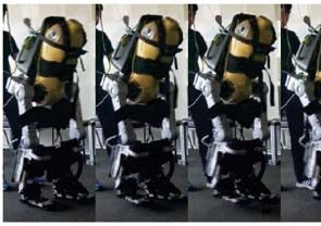
High level control Trajectory tracking
Nominal Joints
Filtering
trajectory targets Tracking
Impact detection
Feet contact Actual joints
sensors positions
Current
Low Level Hardware targets
Fig. 6: Structure of the control loop.
gaits, a feedback-linearizing controller tracking the nominal
outputs is implemented in a simulation. This way, the full
trajectory of the robot is recovered and the periodicity and
stability of the gait are assessed. The joint positions generated
by these simulations are then used as the nominal joint
trajectories to be tracked on the hardware. Gait tiles simulated
walking gait obtained via this procedure is shown in Fig. 5
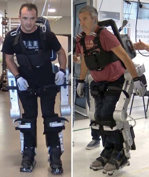
with the corresponding phase portrait plotted in Fig. 7 as the
nominal gait (red), prior to modification of the trajectories on
the hardware (shown in blue). The fact that the phase portraits
are periodic orbits imply that a valid periodic walking gait is Fig. 7: Phase portraits for the dummy during 20s of unas-
generated. sisted walking.
IV. I MPLEMENTATION ON THE E XOSKELETON
one chosen cyclic gait, articular targets for each joints are
The final step of this work is the implementation of the
generated. These targets are the nominal trajectories of the
generated gaits on hardware. This section details some of
joints but modified online based on foot impact detection to
the implementation on ATALANTE, and presents the results
allow for a better transition between steps. These targets are
obtained with multiple users (1 dummy and 3 paraplegic pa-
then sent to a control loop which generates current commands
tients). Importantly, dynamically stable locomotion is realized
at the joint level. The current command is then sent to the
in all cases, and the walking is compared across patients.
motor controller that handles the high-frequency low-level
A. Implementation of gaits on hardware control of the motor.
In order to translate the gaits obtained in simulation Tuning of the trajectory. Finally, the nominal trajectory is
into actual dynamical walking on hardware, the following tuned in order to accommodate for the mechanical imper-
methodology has been followed (as illustrated in Fig. 2). fections and asymmetries of the robot. This tuning happens
Adjusting the Exoskeleton dimensions. Since all patients during a series of walking experiments with a mannequin
have different sizes and body shapes, the hardware has been until the desired behavior is achieved. Tuning generally
designed so that certain dimensions can be adjusted (cf. improves the stability and robustness of the gait after a few
green links in Fig. 3). Using the measurements made to trials.
generate the patient model, the dimensions of the exoskeleton
B. Experimental results with a dummy
are adjusted to align the robot’s joints with the patient’s
joints. This allows to minimize the internal stresses at the To evaluate the controllers, experiments are first carried
attachment points between the patient and the exoskeleton out using a mannequin or dummy (cf. Fig. 5). As we can
arising from the highly hyper-static nature of the human- see in Fig. 7, the nominal and target trajectories (in red and
exoskeleton mechanism. blue respectively) are marginally different after the tuning
Embedded systems structure. The exoskeleton is controlled and high-level filtering of the nominal trajectories (cf. Fig.
by a central computer board running a real-time operating 6). The target gait is followed with relatively good accuracy
system and in charge of all high level computations. This resulting in stable dynamic walking of the hardware.
central computer then sends commands to motor controllers C. Experimental results with human subjects
that handle the low-level operation of brushless motors.
Digital encoders are present on all the joints of the exoskele- As a result of the successful results obtained with the
ton. IMU’s are located in different parts of the exoskeleton dummy, experiments are carried out with paraplegic patients.
allowing for a better estimation of the pose of the robot. Some characteristics of these patients are summarized in
Furthermore, sensors are present in the feet and provide a Table I.
measurement of the center-of-pressure during walking. Clinical Set-Up. Experiments were conducted in a certi-
In order to get the exoskeleton to realize the desired fied medical center and approved by the ANSM (French
gait, trajectory tracking is implemented (cf. Fig. 6). Given regulatory administration for health products). To prevent
2809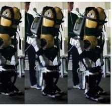
TABLE I: Patients data
                                         Distance
  Patient   Height(m)     Weight(kg)                 speed(m/s)
                                       traveled(m)
     A         1.80           68            8.9         0.11
     B         1.69           80          10.56         0.15
     C         1.80           75            9.5         0.13

                                                                         (a) Selection of phase portraits. The solid lines are the target
                                                                         trajectories. The shaded regions are the measured joints positions.

Fig. 8: Phase portraits for patient A during 60s of unassisted                             (b) Measured motor torques.
walking.

injury from a fall, one person is placed at each side of a
patient. In case of loss of balance, the two assistants catch
the exoskeleton by handles on its sides. Furthermore, a safety
cable is attached to the exoskeleton and an overhead rail (or
gantry). This is a secondary means to secure a patient and
prevent a fall. Hence, assistance is provided only in case of
loss of balance. During walking, the exoskeleton and its user
are self stabilized and no outside assistance was given.
Results. As can be seen in the video at [4] and Fig.
9c, crutch-less dynamically stable exoskeleton walking of
paraplegic patients is achieved as a result of the method-
ology developed in this paper. All patients managed to walk
unassisted for the entire length of the room after a few trials
during which a best gait was chosen and then tuned; Table I
includes the speed of walking and distance traveled.
   The ability to successfully transfer the formal gaits gener-
ated to hardware is illustrated in Fig. 8 for Patient A, wherein
the nominal (blue) and measured (shaded) trajectories are
consistent throughout the experiment. The motors torques
resulting from tracking the nominal trajectories (cf. Fig. 9b)
are also consistent with simulation. Note that motor-torque
saturations are relatively uncommon as the gaits are designed
to account for all hardware limits. To compare the walking               (c) Walking tiles of patients A, B and C (in this order from top to
between patients, a representative selection of phase portraits          bottom).
for each patient are presented in Fig. 9a; even though the gaits
are not the same (as they have been generated to best suit each              Fig. 9: Experimental results for all three patients.
patient), they all display a common fundamental structure.
                                                                  2810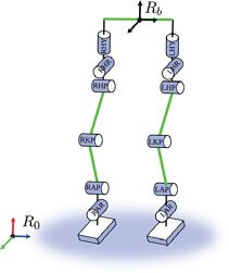
This is further illustrated in gait tiles of the patients walking                [9] John T Betts. Survey of numerical methods for trajectory optimization.
in the exoskeleton (cf. Fig. 9c). While the dynamic walking                          Journal of guidance, control, and dynamics, 21(2):193–207, 1998.
                                                                                [10] Aaron M. Dollar and Hugh Herr. Lower extremity exoskeletons and
gaits obtained are preliminary, and in no way constitute any                         active orthoses: Challenges and state-of-the-art. IEEE Trans. Robot.,
kind of clinical evaluation, the ability to consistently realize                     24(1):144–158, 2008.
them on patients points toward the validity of the framework                    [11] Kevin Fite, Jason Mitchell, Frank Sup, and Michael Goldfarb. Design
                                                                                     and control of an electrically powered knee prosthesis. In Rehabilita-
developed.                                                                           tion robotics, 2007. ICORR 2007. IEEE 10th international conference
                                                                                     on, pages 902–905. IEEE, 2007.
                          V. C ONCLUSIONS                                       [12] Kevin Galloway, Koushil Sreenath, Aaron D. Ames, and Jessy W.
                                                                                     Grizzle. Torque saturation in bipedal robotic walking through control
   This paper has demonstrated the first ever experimental                            lyapunov function based quadratic programs. IEEE Access, 3:323–332,
realization of hands-free dynamic walking by subjects with                           April 2015.
a lower spine injury. The keys to realizing this were novel                     [13] Brent Griffin and Jessy Grizzle. Walking gait optimization for ac-
                                                                                     commodation of unknown terrain height variations. In 2015 American
hardware, stiff enough to physically support a subject, pow-                         Control Conference, pages 4810–4817, 2015.
erful enough to move the device’s legs quickly, and novel                       [14] J. W. Grizzle, C. Chevallereau, R. W. Sinnet, and A. D. Ames. Models,
control mathematics developed over the past 15 years to allow                        feedback control, and open problems of 3D bipedal robotic walking.
                                                                                     Automatica, 50(8):1955 – 1988, 2014.
bipedal robots to walk stably in uncertain environments and                     [15] J Grundmann and A Seireg. Computer control of multi-task exoskele-
with imprecise dynamic models. Importantly, these results                            ton for paraplegics. In Proceedings of the Second CISM/IFTOMM
concretely mark the first steps toward the vision of restoring                        International Symposium on the Theory and Practice of Robots and
                                                                                     Manipulators, pages 233–240, 1977.
locomotion for paraplegics.                                                     [16] Charles R Hargraves and Stephen W Paris. Direct trajectory opti-
   The preliminary results demonstrated very slow walking on                         mization using nonlinear programming and collocation. Journal of
the order of 0.1 m/s. Stable gaits at 0.4 m/s were achieved in                       Guidance, Control, and Dynamics, 10(4):338–342, 1987.
                                                                                [17] Ayonga Hereid, Eric A Cousineau, Christian M Hubicki, and Aaron D
simulation, and such speeds can be expected to be reached                            Ames. 3D dynamic walking with underactuated humanoid robots: A
on the current hardware and with patients. Future work will                          direct collocation framework for optimizing hybrid zero dynamics. In
also provide the ability to stand from a chair, initiate a gait,                     Robotics and Automation (ICRA), 2016 IEEE International Conference
                                                                                     on, pages 1447–1454. IEEE, 2016.
stop, turn, and sit in a chair. However, before providing more                  [18] D Hristic, M Vukobratovic, and M Timotijevic. New model of
gait features, focus will be on improving the basic posture                          autonomous’ active suit’for distrophic patients. In Proceedings of the
of the gaits to be more upright and comfortable, with foot                           International Symposium on External Control of Human Extremities,
                                                                                     pages 33–42, 1981.
roll and heel strike. Better robustness of the overall closed-                  [19] Y. Hurmuzlu, F. Génot, and B. Brogliato. Modeling, stability and con-
loop system is also a general goal. The hope is that these                           trol of biped robots–a general framework. Automatica, 40(10):1647–
future research directions will enable dynamic exoskeleton                           1664, 2004.
                                                                                [20] H Igo Krebs, Neville Hogan, Mindy L Aisen, and Bruce T Volpe.
locomotion in everyday life settings, from traversing up and                         Robot-aided neurorehabilitation. IEEE transactions on rehabilitation
down stairs to walking outdoors in natural environments.                             engineering, 6(1):75–87, 1998.
                                                                                [21] R. M. Murray, Z. Li, S. S. Sastry, and S. S. Sastry. A mathematical
                        ACKNOWLEDGMENT                                               introduction to robotic manipulation. CRC press, 1994.
                                                                                [22] Jacob Reher, Eric A Cousineau, Ayonga Hereid, Christian M Hubicki,
   The authors would like to thank the entire Wandercraft                            and Aaron D Ames. Realizing dynamic and efficient bipedal loco-
                                                                                     motion on the humanoid robot durus. In Robotics and Automation
team which designed ATALANTE, implemented and tested                                 (ICRA), 2016 IEEE International Conference on, pages 1794–1801.
the control algorithms both in simulation and in real condi-                         IEEE, 2016.
tions. Additionally, the authors are grateful to Laurent Praly                  [23] Jacob P Reher, Ayonga Hereid, Shishir Kolathaya, Christian M Hu-
                                                                                     bicki, and Aaron D Ames. Algorithmic foundations of realizing
and Nicolas Petit, researchers at CAS (Mines ParisTech,                              multi-contact locomotion on the humanoid robot durus. In Twelfth
PSL Research University) for their precious scientific support                        International Workshop on Algorithmic Foundations on Robotics, 2016.
since the beginning of Wandercraft, and to Koushil Sreenath                     [24] A Seireg and JG Grundmann. Design of a multitask exoskeletal
                                                                                     walking device for paraplegics. Biomechanics of Medical Devices,
at UC Berkeley for collaborative efforts on realizing dynamic                        pages 569–644, 1981.
walking on exoskeletons.                                                        [25] Frank Sup, Amit Bohara, and Michael Goldfarb. Design and control
                                                                                     of a powered transfemoral prosthesis. The International journal of
                             R EFERENCES                                             robotics research, 27(2):263–273, 2008.
                                                                                [26] M Vukobratovic, D Hristic, and Z Stojiljkovic. Development of active
 [1] Ekso bionics. http://eksobionics.com/eksohealth/patients/. Accessed:            anthropomorphic exoskeletons. Medical and Biological Engineering,
     2017-09-15.                                                                     12(1):66–80, 1974.
 [2] Rewalk. http://rewalk.com/. Accessed: 2017-09-15.                          [27] Michael Wehner, Brendan Quinlivan, Patrick M Aubin, Ernesto
 [3] Rex bionics. http://www.rexbionics.com/. Accessed: 2017-09-15.                  Martinez-Villalpando, Michael Baumann, Leia Stirling, Kenneth Holt,
 [4] Video of the experimental results. https://youtu.be/V30HsyUD4fs.                Robert Wood, and Conor Walsh. A lightweight soft exosuit for
 [5] Wandercraft. http://www.wandercraft.eu/. Accessed: 2017-09-15.                  gait assistance. In Robotics and Automation (ICRA), 2013 IEEE
 [6] Ayush Agrawal, Omar Harib, Ayonga Hereid, Sylvain Finet, Matthieu               International Conference on, pages 3362–3369. IEEE, 2013.
     Masselin, Laurent Praly, Aaron D. Ames, Koushil Sreenath, and              [28] E. R. Westervelt, J. W. Grizzle, C. Chevallereau, J. H. Choi, and
     Jessy W. Grizzle. First steps towards translating HZD control of bipedal        B. Morris. Feedback control of dynamic bipedal robot locomotion.
     robots to decentralized control of exoskeletons. IEEE Access, 5:9919–           CRC press Boca Raton, 2007.
     9934, 2017.                                                                [29] Juanjuan Zhang, Chien Chern Cheah, and Steven H Collins. Experi-
 [7] Aaron D Ames. Human-inspired control of bipedal walking robots.                 mental comparison of torque control methods on an ankle exoskeleton
     IEEE Transactions on Automatic Control, 59(5):1115–1130, 2014.                  during human walking. In Robotics and Automation (ICRA), 2015
 [8] Aaron D Ames, Kevin Galloway, Koushil Sreenath, and Jessy W                     IEEE International Conference on, pages 5584–5589. IEEE, 2015.
     Grizzle. Rapidly exponentially stabilizing control lyapunov functions
     and hybrid zero dynamics. IEEE Trans. on Automatic Control,
     59(4):876–891, 2014.

                                                                            2811
You can also read