Triplanar Displacement Mapping for Terrain Rendering
←
→
Page content transcription
If your browser does not render page correctly, please read the page content below
EUROGRAPHICS 2020/ F. Banterle and A. Wilkie Short Paper
Triplanar Displacement Mapping for Terrain Rendering
S. Weiss and F. Bayer and R. Westermann
Technical University of Munich, Germany
Author's Preprint
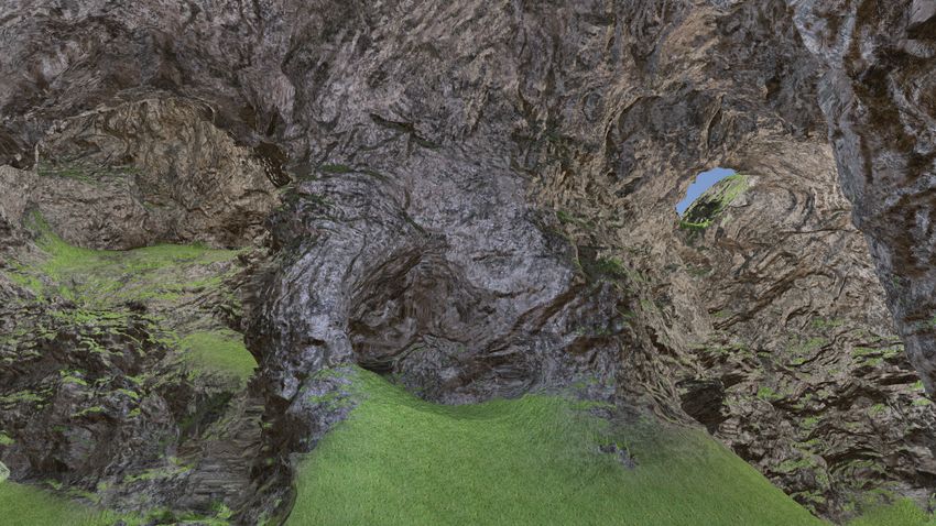
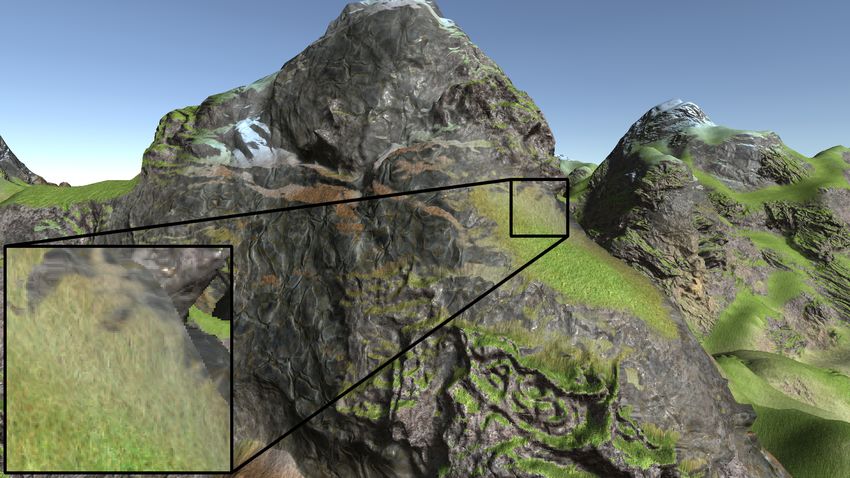
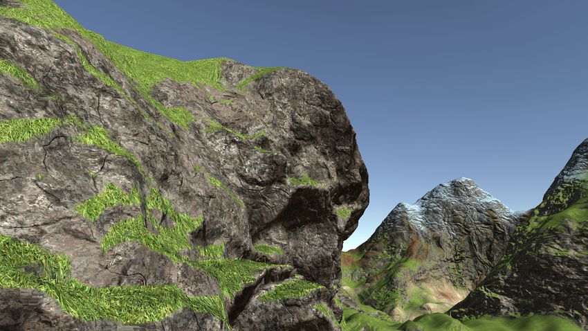
(a) UV-Mapping (b) Triplanar Texturing (c) Triplanar Displacement, 8x (d) adaptive Triplanar Displacement
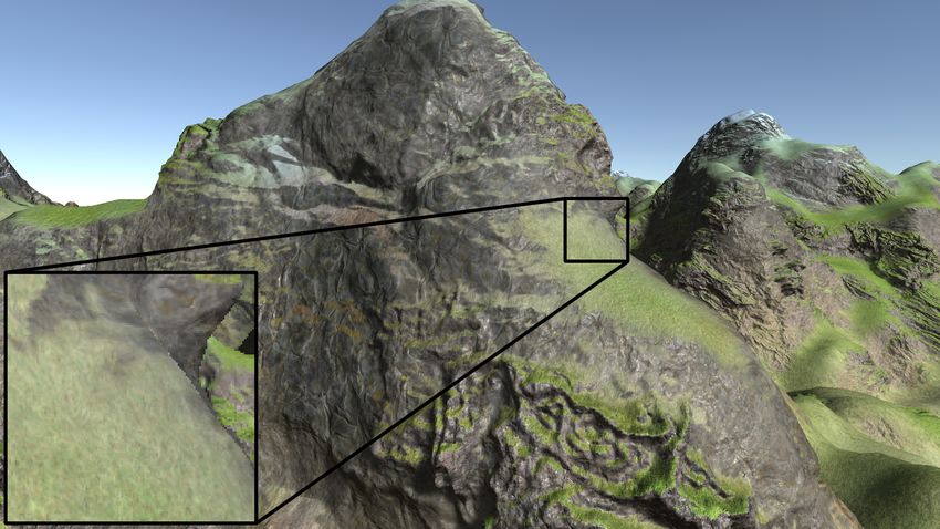
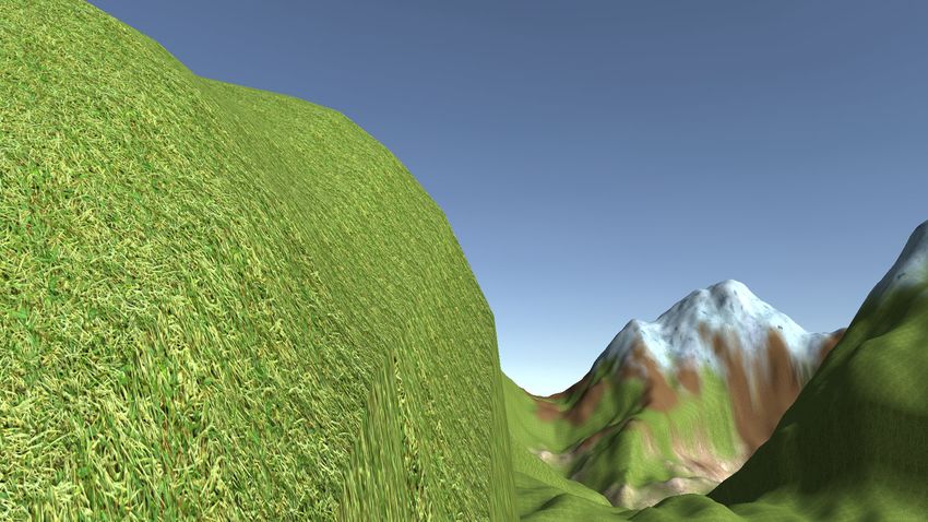
Figure 1: Severe stretching can occur when a 2D texture is projected onto a terrain field using uv-mapping (a), which can be avoided via
triplanar texture mapping (b).We propose triplanar displacement mapping (c,d), a combination of triplanar texture mapping with tessellation,
to add geometric details to a heightfield. We extend this method via an adaptive, displacement-aware tessellation scheme (d) that achieves the
same visual quality without requiring a high-resolution base mesh (c).
Abstract
Heightmap-based terrain representations are common in computer games and simulations. However, adding geometric details to
such a representation during rendering on the GPU is difficult to achieve. In this paper, we propose a combination of triplanar
mapping, displacement mapping, and tessellation on the GPU, to create extruded geometry along steep faces of heightmap-based
terrain fields on-the-fky during rendering. The method allows rendering geometric details such as overhangs and boulders,
without explicit triangulation. We further demonstrate how to handle collisions and shadows for the enriched geometry.
1. Introduction methods for rendering heightmap-based terrain representations, by
adding fine geometric details to the overall shape of the terrain. In
In computer graphics, terrains are often represented by
this paper we present methods to
heightmaps [GGP∗ 19]. A heightmap is a two-dimensional scalar
field, usually given at the vertices of a regular grid, where every • adaptively displace vertices using triplanar-sampled displacement
scalar value indicates a height over some base elevation. Creating a maps to create overhangs and holes,
polygonal terrain representation that can be rendered on the GPU is • compute correct normal vectors on the displaced and normal-
then performed by triangulating every cell comprised of 4 vertices mapped terrain,
into two triangles, and displacing vertices along the vertical axis. • optimize the texture access patterns, and to
A heightmap representation, however, has limitations, since it can- • include triplanar displacement mapping in existing game engines
not represent geometric structures like overhangs and requires high with collisions and multiple lights and shadows.
resolution to faithfully represent fine geometric details.
We demonstrate that our method can be applied to both heightmap-
In scenarios where overhangs are crucial to the look of the ter- and voxel-based terrain representations,and can be easily included
rain, a possible solution is to model the terrain as a surface in 3D into existing game engines. The source code of our Unity imple-
using a high-resolution polygon model [LO10, PGGM09, BKRE19]. mentation is published at https://github.com/flojo33/
Alternatively, the terrain can be encoded as an implicit surface in Triplanar-Displacement-Mapping.
a 3D scalar field that is represented by a voxel model, and voxel-
based ray-casting is then used to render the surface [GM01, Gei07,
WQK99, LO10]. Both approaches can render overhangs and caves, 2. Related Work
but increase bandwidth, memory requirements and rendering load.
Many previous works in terrain rendering have focused on the han-
We propose Triplanar Displacement Mapping (TDM), a combi- dling of very large terrain fields with continuous level-of-detail
nation of triplanar texture mapping and displacement mapping with and out-of-core rendering [DWS∗ 97, LH04, LRC∗ 03, Str09, SPC18,
adaptive tessellation. This method works in tandem with existing DKW10, DKW09]. For a thorough overview, let us refer to the
c 2020 The Author(s)
Eurographics Proceedings c 2020 The Eurographics Association.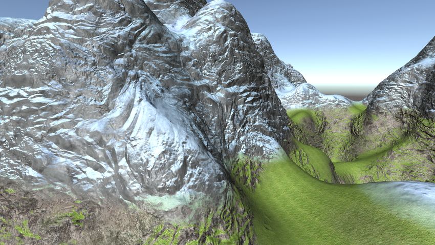
S. Weiss & F. Bayer & R. Westermann / Triplanar Displacement Mapping for Terrain Rendering

                            Vertex Shader       Tessellation        Tessellation                     Fragment
                            (pass-through)     Control Shader     Evaluation Shader                   Shader

                                               Tessellation Map   Displacement Maps     Normal Maps             Color Maps

                                                                   Dx    Dy    Dz       Nx    Ny   Nz      Cx      Cy    Cz
                             Splat weights                              ···                  ···                  ···
                                                                   Dx    Dy    Dz       Nx    Ny   Nz      Cx      Cy    Cz

                     Figure 2: Overview of our Triplanar Displacement Mapping pipeline. We apply                                 Figure 3: Triplanar displacement mapping ap-
                     triplanar mapping with splat maps in every stage to sample displacements, detailed                          plied to a heightmap-based terrain. The green
                     normals and colors independently.                                                                           lines represent displacement maps projected onto
                                                                                                                                 the blue base heightmapped terrain.

                    recent report by Galin et al. [GGP∗ 19]. Closely related to our ap-                     normal n by a value sampled from a displacement texture D, at
                    proach is the work by Gamito and Musgrave [GM01], which can                             texture coordinate u [SKU08]:
                    render overhangs by ray-tracing a heightmap that is warped by a flow
                    field. To add fine-scale geometric detail to arbitrary polygon mod-                                                    x ← x + αD(u)n,                                      (2)
                    els, displacement mapping is a common approach for uv-mapped                            with an optional scaling factor α for the strength of the displacement.
                    objects [WWT∗ 03, Don05, SKU08, ZR19]. To the best of our knowl-
Author's Preprint

                    edge, however, we have not seen it being applied with triplanar                            Our main idea is to obtain the displacement value D from triplanar
                    mapping.                                                                                mapping (see Eq. (1)) instead of a single texture map. Therefore, the
                                                                                                            terrain is first tessellated adaptively (Sec. 3.2), to generate additional
                                                                                                            geometry that can be displaced. Then, the displacement is performed
                    3. Method
                                                                                                            in the tessellation evaluation shader using the triplanar textures
                    Our proposed method adds more details to the vertical faces of                          (Fig. 3):
                    cliffs based on displacement maps. It first utilizes GPU tessella-
                                                                                                                  x ← x + α (bx (n)Dx (y, z) + by (n)Dy (x, z) + bz (n)Dz (x, y)) n. (3)
                    tion [NKF∗ 15] to create more vertices along faces of the terrain
                    that should be extruded or indented. Then, it projects displacement
                    maps onto the terrain using triplanar mapping (Sec. 3.1). These                            After displacing the vertices, the vertex normal does not match
                    maps can displace the newly generated geometry to create more                           the geometry anymore. This can be corrected by recomput-
                    realistic details like bumpy rocks and small overhangs. Next, normal                    ing the normals using per-fragment derivatives as presented by
                    maps are sampled to compensate for the displaced surface. Color                         Mikkelsen [Mik10], which, however, leads to rather flat-looking
                    maps are then sampled based on the displaced positions and sam-                         surfaces. We avoid this by computing custom normal maps that
                    pled normals. The terrain is adaptively tessellated (Sec. 3.2), and                     compensate for the displacement maps using a Sobel filter [SF68].
                    a number of optimizations are performed to minimize texture ac-                                                 "       #         "        #    !T
                                                                                                                                      −1 0 1       1 −1 −2 −1
                    cess operations(Sec. 3.3). To support multiple terrain types, we use                          n = normalize( −2 0 2 ∗ D, , 0 0 0 ∗ D ) (4)
                    texture splatting [CM93]. In texture splatting, a four-channel splat                                              −1 0 1       α 1 2 1
                    map (stored per-vertex) specifies interpolation weights between four
                    different materials. The whole pipeline is depicted in Fig. 2.                          The normals derived from these textures are then projected onto the
                                                                                                            surface using reoriented normal mapping [Gol17], and then blended
                                                                                                            using the blend weights as well. The normals are then used for the
                    3.1. Triplanar Displacement Mapping                                                     triplanar texture mapping of the color textures, see Fig. 4.
                    In traditional uv-mapping, textures are mapped to a surface mesh                           An additional normal map can be blended onto the surface to
                    using texture coordinates that are stored for each vertex of the mesh.                  add details at a finer resolution within a certain terrain area. This is
                    Since along steep cliffs, texture coordinates are close in texture                      achieved by applying reoriented normal mapping again using the
                    space but represent details at large spatial distances, this often leads                normal mapping result as described before as the base surface. This
                    to severe stretching. To compensate this effect, triplanar texture                      adds details during the shading process but does not influence the
                    mapping [Nic08, p.16], [Gol17] is often used. The idea is to use                        triplanar blending weights.
                    three textures using different parametrizations XY, XZ and YZ
                    and blend them based on the normal vector. Let x = (x, y, z)T be
                    the position of the current fragment with normal n, Tx , Ty , Tz are
                    respectively the three textures, bx , by , bz are the corresponding blend
                    factors. Then, the final color is computed as
                             c = bx (n)Tx (y, z) + by (n)Ty (x, z) + bz (n)Tz (x, y).          (1)               (a)                                      (b)
                      We extend this principle of triplanar texture mapping to displace                     Figure 4: Difference if detailed normal maps and color blending
                    geometric details along a base terrain. In traditional displacement                     after normal mapping are disabled (a) or enabled (b).
                    mapping on uv-mapped meshes, the vertex x is moved along its

                                                                                                                                                                               c 2020 The Author(s)
                                                                                                                                        Eurographics Proceedings c 2020 The Eurographics Association.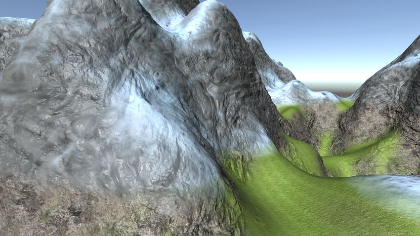
S. Weiss & F. Bayer & R. Westermann / Triplanar Displacement Mapping for Terrain Rendering
(a) (b) (c)
Figure 6: Top: Influence of blend factor offset on image quality.
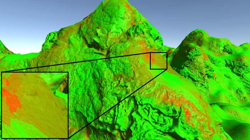
Figure 5: The tessellation map defines regions with lower and Bottom: Number of texture samples (low (green) to high (red)), for
higher roughness and correspondingly low and high tesselation, low (a), medium (b) and high (c) optimization.
e.g., green and red determine grass and stone, respectively.
GPU Memory, Mesh+Texture Frame Time
100%, 1.17ms
base uv
3.2. Adaptive Level-of-Detail 100%, 52MB
117%, 1.37ms
Since we utilize tessellation to generate the heigh-resolution dis- triplanar texturing
254%, 132MB
placement geometry, the amount of tessellation is specified on a
736%, 8.57ms
per-triangle level. For example, Cantlay [Can11] demonstrates ad- 8x resolution
739%, 384MB
justment of tessellation factors according to the camera distance, so
Author's Preprint
adaptive tessellation 186%, 2.17ms
that closer triangles are subdivided more. We extend this method +tripl. disp. map. 255%, 132.5MB
by adding a factor that limits the amount of tessellation based on 296%, 3.45ms
+100 dynamic lights
the expected displacement. We note that different terrain types re- 272%, 141.5MB
relative change to the base in % and absolute values
quire different strengths of displacement, and hence require different
amounts of tessellation. To account for this, a maximal tessellation Figure 7: Benchmarking results for a simple terrain using uv-
factor per terrain type is fist selected manually. Then, a tessellation mapping or triplanar texturing in comparison to a terrain using
map—stored as per-vertex attributes—is computed in a preprocess, triplanar displacement mapping on a brute force 8x resolution grid
by blending the per-material tessellation factors using triplanar map- and a dynamically tessellated terrain of also up to more than 8x
ping and texture splatting. Fig. 5 demonstrates the use of the tessel- resolution.
lation map to keep the number of triangles low in areas with less
details such as grass, and increase the tessellation factor in rough
areas like boulders. generated around the player. As the player moves over the terrain,
the collision mesh is updated around the player asynchronously. We
refer to the accompanying video for a demonstration.
3.3. Optimized Texture Access
Shadows using traditional shadow mapping can be used in the
We support 4 different terrain types via texture splatting. Hence, our pipeline without major changes. Let us only note that it is crucial
approach requires 12 textures: three for the sides of the triplanar that during rendering the shadow map from the light position, the
mapping for each of the 4 different terrain types. Each of the 12 same tessellation as if the terrain was seen from the player camera
textures stores 11 attributes that are packed into three rgba-textures: has to be used to avoid false shadowing.
• Surface map (tessellation): surface normal X and Y, displacement
map, alpha is unused 4. Results and Benchmarks
• Color map (fragment): albedo rgb, emission intensity
Our system was tested on a workstation with an i7-9700k CPU, an
• Detail map (fragment): smoothness, metallic, detail normal X, Y
RTX 2060 GPU and 16GB of RAM. To demonstrate the perfor-
In total, this requires to sample up to 36 textures per fragment. mance of triplanar displacement mapping with adaptive tessellation
This number, however, can be drastically reduced by a) reducing in comparison to a simple uv-mapped terrain, a camera was set up
the area where different terrain types overlap in the splat map, b) to fly over a Perlin Noise-based [EMP∗ 03, p. 69] infinite terrain for
sampling splat textures only if the weight is greater than some offset, a fixed number of frames (250.000) using different settings. The
c) sampling triplanar textures only if the blend factor is greater average frame time and memory was recorded for different shader
than some offset [Gol14], see Fig. 6. These optimizations make variants and terrain resolutions (Fig. 7). As one can see, our method
the transitions between terrain types appear sharper, which is often introduces only a slight overhead in both render time and required
desired (Fig. 6b). However, care must be taken as to not introduce memory, but offers much better visual quality ( see Fig. 1 for a visual
sharp discontinuities due to high offsets (Fig. 6c). comparison). To achieve the same quality using heightmaps without
tessellation and displacement mapping, a grid of 8x the resolution
needed and the memory requirements increase accordingly from
3.4. Collision and Shadows
approx. 52MB to 384MB. Our method also fits well into a deferred
To support collisions with the displaced terrain, the steps of the lighting pipeline, i.e., up to 100 dynamic lights can be used at a
tessellation engine and the vertex displacements are replicated on frame time of only 3.45ms. We refer to the accompanying video for
the CPU, and a collision mesh that matches the rendered terrain is an extended visual comparison and examples.
c 2020 The Author(s)
Eurographics Proceedings c 2020 The Eurographics Association.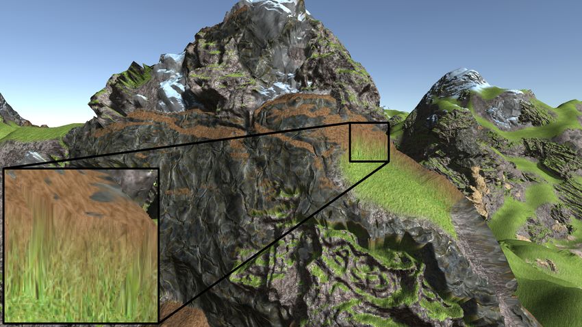
S. Weiss & F. Bayer & R. Westermann / Triplanar Displacement Mapping for Terrain Rendering

                       Furthermore, our method can also be applied to different terrain           [EMP∗ 03] E BERT D., M USGRAVE F., P EACHEY D., P ERLIN K., W OR -
                    meshes as indicated in Fig. 8. Here the mesh was created using the              LEY S., M ARK W., H ART J.: Texturing and Modeling: A Procedural

                    marching cubes algorithm to render a surface based on 3D noise                  Approach: Third Edition. Elsevier Inc., United States, 2003. 3
                    functions [Gei07]. This demonstrates that our proposed method can             [Gei07] G EISS R.: Generating complex procedural terrains using the gpu.
                                                                                                    GPU gems 3 (2007), 7–37. 1, 4
                    be applied to arbitrary geometry where an explicit uv-mapping is
                    still unfeasible.                                                             [GGP∗ 19] G ALIN E., G UÃ L’RIN E., P EYTAVIE A., C ORDONNIER G.,
                                                                                                    C ANI M.-P., B ENES B., G AIN J.: A review of digital terrain modeling.
                                                                                                    Computer Graphics Forum 38, 2 (2019), 553–577. doi:10.1111/
                                                                                                    cgf.13657. 1, 2
                                                                                                  [GM01] G AMITO M. N., M USGRAVE F. K.: Procedural landscapes with
                                                                                                    overhangs. In 10th Portuguese Computer Graphics Meeting (2001), vol. 2,
                                                                                                    Citeseer. 1, 2
                     (a)                                    (b)                                   [Gol14] G OLLENT    M.:         Triplanar   mapping   textur-
                                                                                                    ing arbitrary surfaces, 2014.         Accessed 02/21/2020.
                    Figure 8: Cave inside a voxel terrain without (a) and with (b)                  URL:            https://gdcvault.com/play/1020394/
                    Triplanar Displacement Mapping.                                                 Landscape-Creation-and-Rendering-in. 3
                                                                                                  [Gol17] G OLUS B.: Normal mapping for a triplanar shader, 9 2017.
                                                                                                    Accessed 02/21/2020. URL: https://medium.com/@bgolus/
                                                                                                    normal-mapping-for-a-triplanar-shader-10bf39dca05a.
                                                                                                    2
Author's Preprint

                    5. Conclusion                                                                 [LH04] L OSASSO F., H OPPE H.: Geometry clipmaps: terrain rendering
                                                                                                    using nested regular grids. In ACM Transactions on Graphics (TOG)
                    We have presented a method to add fine geometric details to triplanar           (2004), vol. 23, ACM, pp. 769–776. 1
                    textured terrain using displacement mapping. It allows to create              [LO10] L ENGYEL E. S., OWENS J. D.: Voxel-based terrain for real-time
                    additional geometric details like overhangs that greatly enhance the            virtual simulations. University of California, Davis, 2010. 1
                    degree of realism. We have demonstrated that our approach works in            [LRC∗ 03] L UEBKE D., R EDDY M., C OHEN J. D., VARSHNEY A., WAT-
                    tandem with existing methods to render heightmap- or voxel-based                SON B., H UEBNER R.: Level of detail for 3D graphics. Morgan Kauf-
                    terrain, and can easily be included in existing game engines and                mann, 2003. 1
                    supports deferred lighting and collision tests. Our approach requires         [Mik10] M IKKELSEN M. S.: Bump mapping unparametrized surfaces on
                    only slightly more memory than traditional triplanar mapped terrain             the gpu. Journal of Graphics, GPU, and Game Tools 15, 1 (2010), 49–61.
                    with splat maps. With the presented optimization to reduce the                  2
                    number of texture fetches, we achieve interactive frame rates even            [Nic08] N ICHOLSON K.: GPU Based Algorithms for Terrain Texturing.
                    with many dynamic light sources. It vastly outperforms approaches               Master’s thesis, University of Canterbury, Christchurch, New Zealand,
                                                                                                    2008. 2
                    using high-resolution 3D polygon models of the same visual quality
                    regarding both frame rates and memory. In the future, we would                [NKF∗ 15] N IESSNER M., K EINERT B., F ISHER M., S TAMMINGER M.,
                                                                                                    L OOP C., S CHÄFER H.: Real-time rendering techniques with hardware
                    like to investigate how this method can be included in an RTX                   tessellation. Computer Graphics Forum 35 (9 2015). 2
                    raytracing framework to support reflections and global illumination
                                                                                                  [PGGM09] P EYTAVIE A., G ALIN E., G ROSJEAN J., M ÉRILLOU S.:
                    in real-time.                                                                   Arches: a framework for modeling complex terrains. Computer Graphics
                                                                                                    Forum 28 (4 2009), 457 – 467. 1
                                                                                                  [SF68] S OBEL I., F ELDMAN G.: A 3x3 isotropic gradient operator for
                    References                                                                      image processing. a talk at the Stanford Artificial Project in (1968),
                                                                                                    271–272. 2
                    [BKRE19] B ECHER M., K RONE M., R EINA G., E RTL T.: Feature-based
                      volumetric terrain generation and decoration. IEEE Transactions on          [SKU08] S ZIRMAY-K ALOS L., U MENHOFFER T.: Displacement mapping
                      Visualization and Computer Graphics 25, 2 (2 2019), 1283–1296. 1              on the gpu-state of the art. In Computer Graphics Forum (2008), vol. 27,
                                                                                                    Wiley Online Library, pp. 1567–1592. 2
                    [Can11] C ANTLAY I.: Directx 11 terrain tessellation. Nvidia whitepaper
                      8, 11 (2011), 3. 3                                                          [SPC18] S ILVESTRE A., P EREIRA J., C OSTA V.: A real-time terrain
                                                                                                    ray-tracing engine. In 2018 International Conference on Graphics and
                    [CM93] C RAWFIS R. A., M AX N.: Texture splats for 3d scalar and vector         Interaction (ICGI) (11 2018), pp. 1–8. doi:10.1109/ITCGI.2018.
                      field visualization. In Proceedings of the 4th conference on Visualiza-       8602735. 1
                      tion’93 (1993), IEEE Computer Society, pp. 261–266. 2
                                                                                                  [Str09] S TRUGAR F.: Continuous distance-dependent level of detail for
                    [DKW09] D ICK C., K RÜGER J. H., W ESTERMANN R.: Gpu ray-casting                 rendering heightmaps. Journal of graphics, GPU, and game tools 14, 4
                      for scalable terrain rendering. In Eurographics (Areas Papers) (2009),         (2009), 57–74. 1
                      Citeseer, pp. 43–50. 1
                                                                                                  [WQK99] WAN M., Q U H., K AUFMAN A.: Virtual flythrough over
                    [DKW10] D ICK C., K RÜGER J., W ESTERMANN R.: Gpu-aware hybrid                  a voxel-based terrain. In Proceedings IEEE Virtual Reality (Cat. No.
                      terrain rendering. Proceedings of IADIS computer graphics, visualization,     99CB36316) (1999), IEEE, pp. 53–60. 1
                      computer vision and image processing 10 (2010), 3–10. 1
                                                                                                  [WWT∗ 03] WANG L., WANG X., T ONG X., L IN S., H U S., G UO B.,
                    [Don05] D ONNELLY W.: Per-pixel displacement mapping with distance              S HUM H.-Y., S HUM H.-Y., S HUM H.-Y.: View-dependent displacement
                      functions. GPU gems 2, 22 (2005), 3. 2                                        mapping. In ACM Transactions on graphics (TOG) (2003), vol. 22, ACM,
                                                                                                    pp. 334–339. 2
                    [DWS∗ 97] D UCHAINEAU M., W OLINSKY M., S IGETI D. E., M ILLER
                      M. C., A LDRICH C., M INEEV-W EINSTEIN M. B.: Roaming terrain:              [ZR19] Z IRR T., R ITSCHEL T.: Distortion-free displacement mapping.
                      real-time optimally adapting meshes. In Proceedings. Visualization’97         In Computer Graphics Forum (2019), vol. 38, Wiley Online Library,
                      (Cat. No. 97CB36155) (1997), IEEE, pp. 81–88. 1                               pp. 53–62. 2

                                                                                                                                                                 c 2020 The Author(s)
                                                                                                                          Eurographics Proceedings c 2020 The Eurographics Association.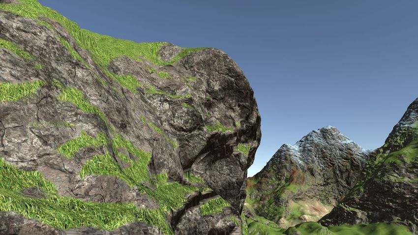
You can also read