User manual Translation of the original instructions
←
→
Page content transcription
If your browser does not render page correctly, please read the page content below
Absolute single-/multi-turn encoder TRT/S3
with PROFIsafe over PROFINET interface               Document no.: TRT 12846 NE

Relevant data sheet TRT 12845                        Date: 20.02.2020

                        User manual
               Translation of the original instructions

TWK-ELEKTRONIK GmbH           40210 Düsseldorf                        info@twk.de
Bismarckstraße 108            Tel.: +49 211 961170            visit us at | twk.de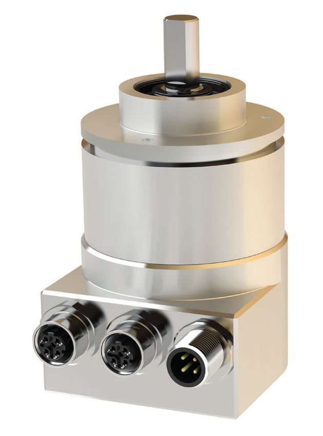
COPYRIGHT: The Operating Instructions TRT 12846
                      is owned by TWK-ELEKTRONIK GMBH and is
              protected by copyright laws and international treaty provisions.

                          © 2020 by TWK-ELEKTRONIK GMBH
                     POB 10 50 63 ■ 40041 Düsseldorf ■ Germany
                     Tel. +49/211/96 11 70 ■ Fax +49/211/63 77 05
                               info@twk.de ■ www.twk.de

Datum: 20.02.2020		                     Seite 2 von 49                     Document no. TRT 12846 NE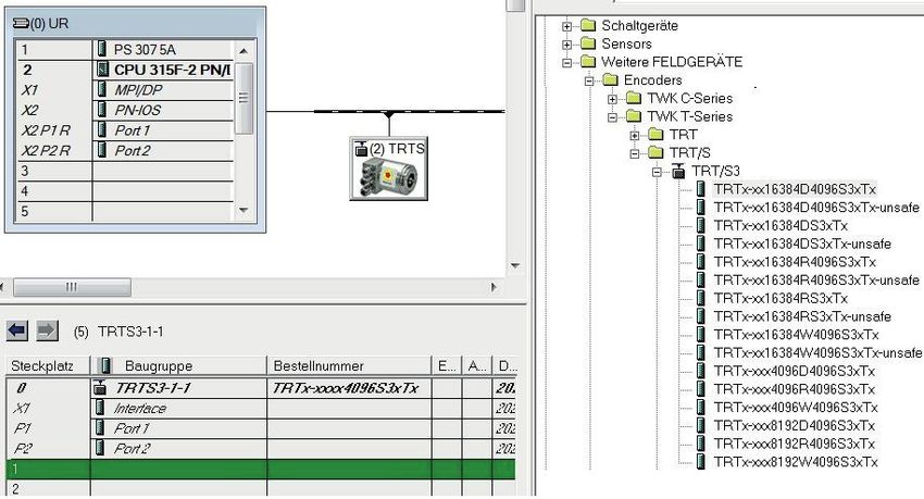
Table of contents

Table of contents

1. Safety instructions............................................................................................................................6
    1.1 Scope............................................................................................................................................6
    1.2 Documentation..............................................................................................................................6
    1.3 Proper use....................................................................................................................................6
    1.4 Commissioning.............................................................................................................................6

2. General information..........................................................................................................................7

3. Installation.........................................................................................................................................8
    3.1 General information .....................................................................................................................8
    3.2 Electrical connection.....................................................................................................................8
    3.3 Status LEDs..................................................................................................................................9
    3.4 Project planning............................................................................................................................9

4. Project planning with Simatic Step7.............................................................................................10

4.1 Step7, Distributed Satety - Simatic Manager..............................................................................10
    4.1.1 Prerequisites............................................................................................................................10
    4.1.2 Installation of the GSD file.......................................................................................................10
    4.1.3 Installing the absolute encoder................................................................................................ 11
    4.1.4 Install module...........................................................................................................................12
    4.1.5 Setting the network data (properties TRT/S3).........................................................................14
    4.1.6 Setting the absolute encoder (properties of the module).........................................................15
      4.1.6.1 Setting the I/O address......................................................................................................15
      4.1.6.2 Parameterising the absolute encoder................................................................................15
      4.1.6.3 Setting the F parameters...................................................................................................16
    4.1.7 Setting real time mode and the updating time.........................................................................17
    4.1.8 Planning of "Device exchange without programming device" and "Automatic commissioning".... 17
    4.1.9 Assignment of the device name...............................................................................................18
    4.1.10 Resetting to the default settings............................................................................................19

4.2 Step7, Safety Advance - TIA-Portal..............................................................................................20
    4.2.1 Prerequisites............................................................................................................................20
    4.2.2 Installation of the GSD file.......................................................................................................20
    4.2.3 Installing the absolute encoder................................................................................................21
    4.2.4 Install module...........................................................................................................................22
    4.2.5 Setting the network data..........................................................................................................23
    4.2.5.1 Setting the PROFINET / PROFIsafe Adresse.......................................................................23

Datum: 20.02.2020		                                                  Seite 3 von 49                                 Document no. TRT 12846 NE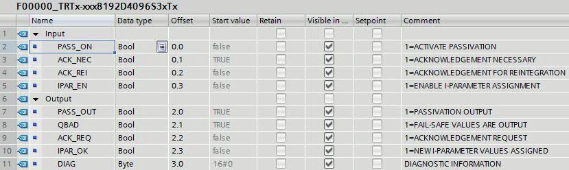
Table of contents

    4.2.5.2 IP-Adresse............................................................................................................................24
    4.2.5.3 Prioritized startup, media redundancy, update time and synchronisation.............................24
    4.2.6 Setting the absolute encoder (properties of the module).........................................................24
      4.2.6.1 Setting the I/O address......................................................................................................24
      4.2.6.2 Parameterising the absolute encoder................................................................................25
      4.2.6.3 Setting the F parameters...................................................................................................25
    4.2.7 Planning of "Device exchange without programming device" and "Automatic commissioning"....26
    4.2.8 Assignment of the device name...............................................................................................27
    4.2.9 Resetting to the factory settings..............................................................................................28
    4.3 Application program....................................................................................................................29
      4.3.1 Remarks................................................................................................................................29
      4.3.2 F-Peripherie-DB....................................................................................................................29
      4.3.3 Accessing the encoder in the F program..............................................................................29
      4.3.4 Example program..................................................................................................................30

5. I/O data.............................................................................................................................................39
    5.1 Overview.....................................................................................................................................39
    5.1.1 Output code R and W..............................................................................................................39
    5.1.2 Output code D..........................................................................................................................39
    5.3 Position data...............................................................................................................................39
      5.3.1 Data format coding R............................................................................................................40
      5.3.2. Data format coding W..........................................................................................................40
      5.3.3 Data format coding D............................................................................................................40
    5.4 Velocity.......................................................................................................................................40
    5.5 F input data.................................................................................................................................41
    5.6 Control word...............................................................................................................................41
    5.7 Preset value (reference value)....................................................................................................41
      5.7.1 Data format coding R............................................................................................................42
      5.7.2. Data format coding W..........................................................................................................42
      5.7.3 Data format coding D............................................................................................................42
    5.8 F output data...............................................................................................................................42

6. Parameterisation.............................................................................................................................43
    6.1 Encoder parameter.....................................................................................................................43
      6.1.1 Overview...............................................................................................................................43
      6.1.2 Description of the absolute encoder parameters..................................................................43
    6.2 F parameter................................................................................................................................44
      6.2.1 Overview...............................................................................................................................44
      6.2.2 Description of the F parameters............................................................................................44

Datum: 20.02.2020		                                                  Seite 4 von 49                                 Document no. TRT 12846 NE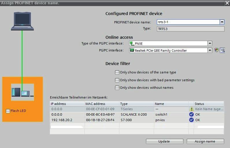
Table of contents

7. Diagnostic........................................................................................................................................46
    7.1 Overview.....................................................................................................................................46
    7.2 PROFINET alarms......................................................................................................................46
    7.3 Diagnostic data records..............................................................................................................47
      7.3.1 Diagnostic data according to Encoder Class 2 Profile..........................................................47

8. Scope of delivery.............................................................................................................................49

9. Literature..........................................................................................................................................49

Datum: 20.02.2020		                                                  Seite 5 von 49                                Document no. TRT 12846 NE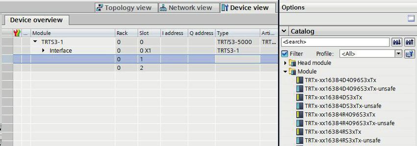
Safety instructions

1. Safety instructions

1.1 Scope

This user manual is valid exclusively for the following absolute encoders with PROFINET interface:

    - TRTxx-xxxxxxxR4096S3xTxx(Multiturn)
    - TRTxx-xxxxxxxxS3xTx (Singleturn)

1.2 Documentation

The following documents must be observed:

    - The owner's system-specific operating instructions

    - This user manual

    - Data sheet number TRT 12845

    - The connection assignment enclosed with the device

    - Assembly instructions TZY10206 enclosed with the device

1.3 Proper use

The TWK-ELEKTRONIK GmbH absolute encoders and linear transducers are used to register angular or linear
positions and make their measured value available in the form of an electrical output signal. As part of a system,
they have to be connected to the downstream electronics and must only be used for this purpose.

1.4 Commissioning

•   The relevant device may only be set up and operated in combination with this and the documentation speci
    fied under point 1.2.

•   Protect the device against mechanical damage during installation and operation.

•   Device commissioning and operation may only be undertaken by a specialist electrician.

•   Do not operate the device outside of the limit values specified in the data sheet.

•   Check all electrical connections before commissioning the system.

Datum: 20.02.2020		                                  Seite 6 von 49                      Document no. TRT 12846 NE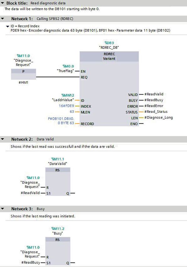
General information

Datum: 20.02.2020		   Seite 7 von 49   Document no. TRT 12846 NE
Installation

3. Installation

3.1 General information

• During installation, observe the profinet assembly guideline PNO order No.: 8.071
• Use only certified profinet cables, connectors and switches (see "PROFINET Cabling and Interconnection
  Technology" PNO order No.: 2.252 and "Installation Guideline PROFINET Part 2: Network Components"
  PNO order No.: 2.252 p2)
• Hubs are not permissible.
• The cable length between two subscribers may be max. 100 m.
• The TWK TRT absolute encoder possesses an integrated switch. This not only enables tree and star topo-
  logies but also the linear topology.
• Media redundancy protocol support enables the establishment of a redundant ring.
• The setting of addresses, the baud rate or terminating resistors on the device is not necessary.

3.2 Electrical connection

The " ...MT01" type absolute encoders have separate connectors for the supply and the PROFINET system. Port
1 or port 2 are optionally available for the PROFINET connection. Due to the integrated switch, it is irrelevant
which port is used.

 Connection                          Designation                                 Connector type
 PROFINET                            Port 1                                      M12x4 D-coded socket
 PROFINET                            Port 2                                      M12x4 D-coded socket
 Voltage supply                      24 VDC                                      M12x4 A-coded pins

Refer to data sheet No. 12886 for connector assignment and ordering information.

                                               UB L/A1 L/A2 NS

                                                                      View of the rear side of the encoder

                                           24 VDC   Port 1   Port 2   Fig.: 1

       24 V voltage supply

                                Profinet                              Profinet

Datum: 20.02.2020		                                    Seite 8 von 49                      Document no. TRT 12846 NE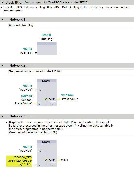
Installation

3.3 Status LEDs

IFour LEDs are housed in the absolute encoder's connecting cap. These have the following meaning:

   UB      Link 1      Link 2            Status
                                                           Description
  (VS)      (L1)        (L2)              (NS)

 green     green       green           green/red
   on                                                      Operating voltage available

             on                                            Network connection established

                         on                                Network connection established

                                          green            Data exchange, device in operation and OK
                                                           Network connection o.k. but no connection to a PROFINET
                                      green flashing
                                                           controler
                                  red, slow flashing       Firmware download mode
                                                           Impermissible parameter or preset value, velocity to high or
                                       red flashing
                                                           wrong modul
                                   Fast red flashing       Device error

                                           red             Connection to the PROFINET controller disrupted

In Chapter 7 diagnosis you can find all diagnosis data of the TRT/S3.

Flashing codes
Errors which lead to encoder system standstill (hard errors) are indicated by a flashing code on the part of the
red NS LED. Following introductory flickering by the red LED, a specific number of flashing cycles are output for
the cause of the error.

                        Number of flashing
                               cycles         Error cause
                       (Duration approx. 1 s)
 Flashing code 1                  1                   F stack error

 Flashing code 2                  2                   CRC error ROM

 Flashing code 3                  3                   RAM/XRAM error

 Flashing code 5                  5                   Programme sequence error

 Flashing code 6                  6                   Power consumption too high

3.4 Project planning

A device description file (GSD file) in the XML format GSDML and an image (bitmap) to integrate the absolute
encoder into a project planning tool are available in the internet under www.twk.de

File name of the GSD file: GSDML-V2.3-TWK-TRTS3-20171122.xml (The version and date may vary
		                                                           depending on the status of the GSD file.)
File name of the bitmap: GSDML-0159-6300-TWK_TRTS.bmp

Project planning using the example of Step7 is explained in the following chapter.

Datum: 20.02.2020		                                     Seite 9 von 49                        Document no. TRT 12846 NE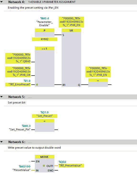
Project planning with Simatic Step7, Distributed Safety - Simatic Manager

4. Project planning with Simatic Step7

4.1 Step7, Distributed Satety - Simatic Manager

This chapter explains the procedure for integrating the TWK TRT/S3 absolute encoder into the PROFINET net-
work of a Siemens S7 control system with Step7 version 5.5. and Distributed Safety version 5.4

4.1.1 Prerequisites

You have created a hardware configuration in accordance with your control system structure and a PROFINET
sub-network.

This is shown here using the example of a CPU314C:

                                                                 Fig.: 2

4.1.2 Installation of the GSD file

• Under Extras in the hardware configuration, select Install GSD files.
• Set "from the directory", "browse" to your GSD file and click on "Install" (see Figure 3).
• The absolute encoder symbol is also installed automatically, provided that it is in the same directory

Note: The GSD file and the encoder symbol are available for download under www.twk.de.

                                                                                                  Fig.: 3

Datum: 20.02.2020		                                Seite 10 von 49                    Document no. TRT 12846 NE
Project planning with Simatic Step7, Distributed Safety - Simatic Manager
After installing the GSD file, the hardware catalogue is automatically updated. The TRT absolute encoder is located
under PROFINET, Further FIELD DEVICES, Encoders, TWK T series, TRT/S.
Fig.: 4
4.1.3 Installing the absolute encoder
Now drag the TRT encoder onto your PROFINET system using the mouse.
Fig.: 5
The absolute encoder's PROFINET interface is then installed together with its default values. The module corre-
sponding to the absolute encoder then has to be installed.
Fig.: 6
Datum: 20.02.2020 Seite 11 von 49 Document no. TRT 12846 NEProject planning with Simatic Step7, Distributed Safety - Simatic Manager
4.1.4 Install module
For the encoder TRT there are modules with different resolutions and data formats available. The module to be
used is defined by the encoder type. Singlturn encoders and 14 bit resolution are available from HW version 2.
With these, it is also possible to add another unsafe module to slot 2. The unsafe module has only input data to
which the data of the safe module is mirrored.
Module Resolution Multiturn Functionality
TRTxx-xxx
12 bit x Safe position (2x integer16), safe speed, preset
4096R4096S3xTx
TRTxx-xxx Safe position (2x integer16, separated single and multiturn data),
12 bit x
4096W4096S3xTx safe speed, preset
TRTxx-xxx Safe position (1x integer32), safe speed, preset (module not use-
12 bit x
4096D4096S3xTx able in Distributed Safety)
TRTxx-xxx
13 bit x Safe position (2x integer16), safe speed, preset
8192R4096S3xTx
TRTxx-xxx Safe position (2x integer16, separated single and multiturn data),
13 bit x
8192W4096S3xTx safe speed, preset
TRTxx-xxx Safe position (1x integer32), safe speed, preset (module not use-
13 bit x
8192D4096S3xTx able in Distributed Safety)
Available from HW version 2
TRTxx-xxx
14 Bit Safe position (2x integer16), safe speed, preset
16384RS3xTx
TRTxx-xxx
14 Bit Position (2x integer16), safe speed
16384RS3xTx-unsafe
TRTxx-xxx Safe position (1x integer32), safe speed, preset (module not use-
14 Bit
16384DS3xTx able in Distributed Safety)
TRTxx-xxx Position (1x integer32), speed (module not useable in Distributed
14 Bit
16384DS3xTx-unsafe Safety)
TRTxx-xxx
14 Bit x Safe position (2x integer16), safe speed, preset
16384R4096S3xTx
TRTxx-xxx
14 Bit x Position (2x integer16), speed
16384R4096S3xTx-unsafe
TRTxx-xxx Safe position (2x integer16, separated single and multiturn data),
14 Bit x
16384W4096S3xTx safe speed, preset
TRTxx-xxx Position (2x integer16, separated single and multiturn data),
14 Bit x
16384W4096S3xTx-unsafe speed
TRTxx-xxx Safe position (1x integer32), safe speed, preset (module not use-
14 Bit x
16384D4096S3xTx able in Distributed Safety)
TRTxx-xxx Position (1x integer32), speed (module not useable in Distributed
14 Bit x
16384D4096S3xTx-unsafe Safety)
Datum: 20.02.2020 Seite 12 von 49 Document no. TRT 12846 NEProject planning with Simatic Step7, Distributed Safety - Simatic Manager
Now drag the module corresponding to your absolute encoder to slot one in the module list using the mouse.
Fig.: 7
The network data can be set by double-clicking onto the absolute encoder symbol (see Chapter 4.1.5), and
the I/O address plus the absolute encoder parameters can be set by double-clicking onto the line "Slot 1"
(see Chapter 4.1.6).
Double-click to set
the network data
(see Chapter 4.1.5)
Double-click to set the
I/O addresses and to
parameterise
(see Chapter 4.1.6)
Fig.: 8
Datum: 20.02.2020 Seite 13 von 49 Document no. TRT 12846 NEProject planning with Simatic Step7, Distributed Safety - Simatic Manager
4.1.5 Setting the network data (properties TRT/S3)
The following dialogue appears by double-clicking onto the absolute encoder symbol (or via the absolute encoder's
context menu). Enter a name which is unique throughout the network to identify the device here. The controller
expects this name when the device logs in. The default name is TRTS3-1.
In the TRT/S3, the Profisafe address must be added to the name. To do this, attach a number between 1 and
65,535 to the end (a special separator between the Profinet name and Profisafe address is not necessary). This
must then be entered for F_Dest_Add under the F parameters (see Chapter 4.1.6.3).
The name assigned here must either be manually allocated to the absolute encoder (see Chapter 4.1.9) or it
can be assigned automatically by the controller using the topology editor (see Chapter 4.1.8 Planning of "Device
exchange without programming device" and "Automatic commissioning").
The device name is stored in the absolute encoder, where it is protected against zero voltage. An installed device
can be exchanged with a brand new device without a programming device or exchanging a memory card. The
correct name is automatically assigned to the new absolute encoder by the controller. To do this, however, the
prerequisites under Chapter 4.1.8 have to be met.
If the tick in front of "IP address assignment by IO controller" is set, the controller automatically assigns an IP
address to the device which contacts it with this name. Manually setting an address as is usual in the case of
previous field bus systems is not necessary.
Fig.: 9
Datum: 20.02.2020 Seite 14 von 49 Document no. TRT 12846 NEProject planning with Simatic Step7, Distributed Safety - Simatic Manager
4.1.6 Setting the absolute encoder (properties of the module)
4.1.6.1 Setting the I/O address
The dialogues for setting the I/O address and for setting the absolute encoder parameters and F-Parameters can
be accessed by double-clicking the installed module (slot 1 line) or via the module's context menu.
Set the address for the input data position, velocity and status and the address for the output data control and
preset in the "Addresses" tab. (See Chapter 5 for the data format).
Fig.: 10
4.1.6.2 Parameterising the absolute encoder
The absolute encoder's parameters can be changed in the "Parameters" tab. An explanation of the parameters
can be found in Chapter 6. After changing the encoder parameters the checksum has to be re-calculated and
entered under the F-parameters (see next chapter).
Fig.: 11
Datum: 20.02.2020 Seite 15 von 49 Document no. TRT 12846 NEProject planning with Simatic Step7, Distributed Safety - Simatic Manager
4.1.6.3 Setting the F parameters
The F parameters must be set in the "PROFIsafe" tab. Here, the Profisafe address attached to the Profinet name
must be set under "F_Dest_Add" and a watchdog time corresponding to your system must be specified under
"F_WD_Time". "F_Source_Add" is assigned automatically by the S7
Once you have changed the rotary
encoder parameters, the checksum
must be recalculated using these
so-called i parameters and must be
entered under "F_iPar_CRC". TWK
provides you with the PsCRC pro-
gramme for calculating the F_iPar_
CRC (see Fig. 12).
An explanation of all F parameters
can be found in Chapter 6.2.
Fig.: 12
The PsCRC programme for calculating the F_
iPar_CRC is available for downloading in the In-
ternet under www.twk.de, documentation area,
PsCRC
Fig.: 13
Datum: 20.02.2020 Seite 16 von 49 Document no. TRT 12846 NEProject planning with Simatic Step7, Distributed Safety - Simatic Manager
4.1.7 Setting real time mode and the updating time
The following dialogues are accessed via the PROFINET system's context menu:
Setting of the IRT mode and
transmission cycle
Setting of the transmission cycle in
RT mode and the updating time
Fig.: 14
Set the transmission cycle and the desired updating time in the corresponding dialogue. Alternatively, the upda-
ting time can also be set via the interface's object properties. The default value is 2 ms for the updating time and
1 ms for the transmission cycle. The minimum updating time for the TRT/3 is 250 µs.
4.1.8 Planning of "Device exchange without programming device" and "Automatic commissioning"
If system restarting without the assignment of a new device name or the IP address is to be possible following
the exchange of an installed absolute encoder with a mint condition device, this must be taken into consideration
during project planning. This also applies to "Automatic commissioning", in which the manual and, in the case of
larger projects, time-consuming assignment of the device name (as described in Chapter 4.1.9) is avoided during
commissioning.
The following prerequisites have to be met:
• The controller and the devices must support the function "Device exchange without interchangeable medium
or programming device" (for the latter, at least the device itself and its neighbouring devices). The TRT/S3 sup
ports this function.
• The function "Device exchange without interchangeable medium" must be activated in the controller. This is
the default setting.
• The devices must be in delivery condition, i.e. they must not yet possess any device name.
Now call the topology editor using the PROFINET system's context menu (see Fig. 12) and define all PROFINET
connections between the subscribers.
If the project is now loaded into the control system and the actual structure corresponds to the planned topology,
all subscribers receive their planned names from the controller and device exchange succeeds without the reas-
signment of the device name.
Datum: 20.02.2020 Seite 17 von 49 Document no. TRT 12846 NEProject planning with Simatic Step7, Distributed Safety - Simatic Manager
4.1.9 Assignment of the device name
If a PROFINET topology has not been defined as described in Chapter 4.1.8 or if the prerequisites for automatic
commissioning are not met, the absolute encoder name must be assigned manually.
With the absolute encoder connected
and the programming device connected
to the control system, select "Target sys-
tem -> Edit Ethernet subscribers" in the
Simatic Manager to do this. Press the
"Browse" button in the subsequent dialo-
gue. All accessible PROFINET subscri-
bers should now be shown as portrayed
in the example in Figure 15.
It can be seen that the absolute enco-
der device type "TWK T series" does not
possess either a valid IP address or a
name. Now mark the absolute encoder
and exit the dialogue with OK.
Fig.: 15
In the subsequent dialogue, enter the
device name, that who have assigned
for this encoder in the project planning
(see Chapter 4.1.5) and click onto the
"Assign name" button. The device
name is then stored in the absolute
encoder, where it is protected against
zero voltage.
The absolute encoder now logs onto
the controller with its device name
and is then provided with a valid IP
address by the controller. This is also
stored in the absolute encoder, where
it is protected against zero voltage.
TRTS3-1
Fig.: 16
Datum: 20.02.2020 Seite 18 von 49 Document no. TRT 12846 NEProject planning with Simatic Step7, Distributed Safety - Simatic Manager 4.1.10 Resetting to the default settings The absolute encoder can be reset to its delivery condition using the "Reset" button in the "Edit Ethernet subscri- bers" dialogue (Figure 16). The following are reset Delivery condition Device name Empty IP-parameters All 0 I&M0-revision counter 0 After resetting, the connection to the profinet controller is closed and the NS LED lights up red. After switching the voltage off/on, the connection can be re-established by assigning the device name. If the connections have been defined using the topology editor, the TRT/S3 restarts automatically with the name assigned during project planning. Datum: 20.02.2020 Seite 19 von 49 Document no. TRT 12846 NE
Project planning with Simatic Step7, Advanced Safety - TIA Portal

4.2 Step7, Safety Advance - TIA-Portal

This chapter explains the procedure for integrating the TWK TRT/S3 absolute encoder into the PROFINET net-
work of a Siemens S7 control system with Step 7 Professional V13 with Safety Advanced.

4.2.1 Prerequisites

You have created a hardware configuration in accordance with your control system structure and a PROFINET
sub-network.

This is shown here using the example of a CPU314C:

                                                                              Fig.: 17

4.2.2 Installation of the GSD file

• In the main menu choose Options, Install general station description file (GSD).
• Set the source path to your GSD file, check the GSD file and click on "Install" (see Figure 3).
• The absolute encoder symbol is also installed automatically, provided that it is in the same directory

Note: The GSD file and the encoder symbol (bitmap) are available for download under www.twk.de.

                                                                                                        Fig.: 18

Datum: 20.02.2020		                                Seite 20 von 49                       Document no. TRT 12846 NE
Project planning with Simatic Step7, Advanced Safety - TIA Portal
After installing the GSD file, the hardware catalogue is automatically updated. The TRT absolute encoder is located
under Further FIELD DEVICES, PROFINET IO, Encoders, TWK-ELEKTRONIK GmbH, TWK T series, TRT/S.
Fig.: 19
4.2.3 Installing the absolute encoder
Now drag the TRT/S3 encoder form the hardware catalog in the netview of your project.
Fig.: 20
Afterwards click on "Not assigned" and assign the encoder to the PROFINET interface of your CPU or draw a
network connection from the encoder to the CPU port with your mouse.
Fig.: 21
The encoder's PROFINET-Interface is now installed with its default values.
Datum: 20.02.2020 Seite 21 von 49 Document no. TRT 12846 NEProject planning with Simatic Step7, Advanced Safety - TIA Portal
4.2.4 Install module
To install the encoder module change to the Device view and drag the module corresponding to you encoder to
the first free slot of the module list.
Fig.: 22
For the encoder TRT there are modules with different resolutions and data formats available. The module to be
used is defined by the encoder type. Singlturn encoders and 14 bit resolution are available from HW version 2.
With these, it is also possible to add another unsafe module to slot 2. The unsafe module has only input data to
which the data of the safe module is mirrored.
Module Resolution Multiturn Functionality
TRTxx-xxx
12 bit x Safe position (2x integer16), safe speed, preset
4096R4096S3xTx
TRTxx-xxx Safe position (2x integer16, separated single and multiturn data),
12 bit x
4096W4096S3xTx safe speed, preset
TRTxx-xxx Safe position (1x integer32), safe speed, preset (module not use-
12 bit x
4096D4096S3xTx able in Distributed Safety)
TRTxx-xxx
13 bit x Safe position (2x integer16), safe speed, preset
8192R4096S3xTx
TRTxx-xxx Safe position (2x integer16, separated single and multiturn data),
13 bit x
8192W4096S3xTx safe speed, preset
TRTxx-xxx Safe position (1x integer32), safe speed, preset (module not use-
13 bit x
8192D4096S3xTx able in Distributed Safety)
Available from HW version 2
TRTxx-xxx
14 Bit Safe position (2x integer16), safe speed, preset
16384RS3xTx
TRTxx-xxx
14 Bit Position (2x integer16), safe speed
16384RS3xTx-unsafe
TRTxx-xxx Safe position (1x integer32), safe speed, preset (module not use-
14 Bit
16384DS3xTx able in Distributed Safety)
TRTxx-xxx Position (1x integer32), speed (module not useable in Distributed
14 Bit
16384DS3xTx-unsafe Safety)
Datum: 20.02.2020 Seite 22 von 49 Document no. TRT 12846 NEProject planning with Simatic Step7, Advanced Safety - TIA Portal
TRTxx-xxx
14 Bit x Safe position (2x integer16), safe speed, preset
16384R4096S3xTx
TRTxx-xxx
14 Bit x Position (2x integer16), speed
16384R4096S3xTx-unsafe
TRTxx-xxx Safe position (2x integer16, separated single and multiturn data),
14 Bit x
16384W4096S3xTx safe speed, preset
TRTxx-xxx Position (2x integer16, separated single and multiturn data),
14 Bit x
16384W4096S3xTx-unsafe speed
TRTxx-xxx Safe position (1x integer32), safe speed, preset (module not use-
14 Bit x
16384D4096S3xTx able in Distributed Safety)
TRTxx-xxx Position (1x integer32), speed (module not useable in Distributed
14 Bit x
16384D4096S3xTx-unsafe Safety)
4.2.5 Setting the network data
Select the encoder in the Device view to show the properties of the PROFINET interface of the TRT/S3.
Fig.: 23
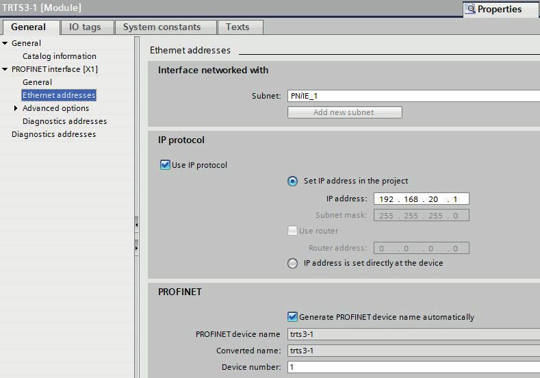
4.2.5.1 Setting the PROFINET / PROFIsafe Adresse
Under "General" enter the PROFINET name which must be unique throughout the network to identify the device.
If Generate PROFINET device name automatically is selected the name which is entered under PROFINET
interface - General will be registered here. The default name is TRTS3-1.
In the TRT/S3, the Profisafe address must be added to the name. To do this, attach a number between 1 and
65,535 to the end (a special separator between the Profinet name and Profisafe address is not necessary). This
must then be entered for F_Dest_Add under the F parameters (see Chapter 4.2.6.3).
The name assigned here must either be manually allocated to the absolute encoder (see Chapter 4.2.8) or it
can be assigned automatically by the controller using the topology editor (see Chapter 4.2.7 Planning of "Device
exchange without programming device" and "Automatic commissioning").
Datum: 20.02.2020 Seite 23 von 49 Document no. TRT 12846 NEProject planning with Simatic Step7, Advanced Safety - TIA Portal
The device name is stored in the absolute encoder, where it is protected against zero voltage. An installed device
can be exchanged with a brand new device without a programming device or exchanging a memory card. The
correct name is automatically assigned to the new absolute encoder by the controller. To do this, however, the
prerequisites under Chapter 4.2.7 have to be met.
4.2.5.2 IP-Adresse
Under "PROFINET interface - Ethernet addresses - IP protocol" the boxes Use IP protocol and Set IP address
in the project should be checked. Step7 automatically assigns an IP address when inserting the device in the
project. Manually setting of the IP address is also possible.
4.2.5.3 Prioritized startup, media redundancy, update time and synchronisation
Via the interface option Prioritized startup the startup time of the TRT/S3 from power on until PROFINET I/O
data exchange can be reduced from approx. 10s to 5s. However, this can only be achieved as of the second
startup.
The TRT/S3 can be used as member (client) in a redundant ring. In case of a line topology one network cable
from the last client to the controler (manager) is necessary only to achieve a redundant communication. Bevor
setting the media redundancy role of the TRT/S3 a MRP domain has to be created and the MRP manager (nor-
mally the controler) to be assigned.
Under "PROFINET interface", "Advanced options", "Real time settings" the desired Update time of the TRT/S3
can be set. The possible values depend on the setting of the send clock of the CPU. The minimal update time for
the TRT/S3 is 250 µs.
The desired real time class can be set under Synchronisation. The TRT/S3 supports the classes RT and IRT.
4.2.6 Setting the absolute encoder (properties of the module)
4.2.6.1 Setting the I/O address
After switching to the device view of the TRT/S3 and selecting slot 1 in the device overview the properties of the
module can be accessed.
Set the PLC addresses for the input data (position, speed and status word) and for the output data (preset and
control word) under I/O addresses (see Chapter 5 for the data format).
Fig.: 24
Datum: 20.02.2020 Seite 24 von 49 Document no. TRT 12846 NEProject planning with Simatic Step7, Advanced Safety - TIA Portal
4.2.6.2 Parameterising the absolute encoder
The absolute encoder's parameters can be changed in the "Module parameters" tab. An explanation of the para-
meters can be found in Chapter 6. After changing the encoder parameters the checksum has to be re-calculated
and entered under the F-parameters (see next chapter).
Fig.: 25
4.2.6.3 Setting the F parameters
The F parameters must be set in the "PROFIsafe" tab. Here, you have to set the Profisafe address attached
to the Profinet name under "F_Dest_Add" and to specify a watchdog time corresponding to your system under
"F_WD_Time"or you to take over the automatic setting . "F_Source_Add" is assigned automatically by the S7
Fig.: 26
At the bottom of this window you can see the number and the symbolic name of the F-IO data block of this en-
coder assigned by Step7.
Datum: 20.02.2020 Seite 25 von 49 Document no. TRT 12846 NEProject planning with Simatic Step7, Advanced Safety - TIA Portal
Once you have changed the rotary encoder pa-
rameters, the checksum must be recalculated
using these so-called i parameters and must be
entered under "F_iPar_CRC". TWK provides
you with the PsCRC programme for calculating
the F_iPar_CRC (see Fig. 27).
It can be downloaded from the internet under
www.twk.de topic Documentation model
PsCRC.
An explanation of all F parameters can be
found in Chapter 6.2.
Fig.: 27
4.2.7 Planning of "Device exchange without programming device" and "Automatic commissioning"
If system restarting without the assignment of a new device name or the IP address is to be possible following
the exchange of an installed absolute encoder with a mint condition device, this must be taken into consideration
during project planning. This also applies to "Automatic commissioning", in which the manual and, in the case of
larger projects, time-consuming assignment of the device name (as described in Chapter 4.2.8) is avoided during
commissioning.
The following prerequisites have to be met:
• The controller and the devices must support the function "Device exchange without interchangeable medium
or programming device" (for the latter, at least the device itself and its neighbouring devices). The TRT/S3 sup
ports this function.
• The function "Device exchange without interchangeable medium" must be activated in the controller. This is
the default setting.
• The devices must be in delivery condition, i.e. they must not yet possess any device name.
Now call the topology editor using the PROFINET system's context menu and define all PROFINET connections
between the subscribers.
If the project is now loaded into the control system and the actual structure corresponds to the planned topology,
all subscribers receive their planned names from the controller and device exchange succeeds without the reas-
signment of the device name.
Datum: 20.02.2020 Seite 26 von 49 Document no. TRT 12846 NEProject planning with Simatic Step7, Advanced Safety - TIA Portal
4.2.8 Assignment of the device name
If a PROFINET topology has not been defined as described in Chapter 4.2.7 or if the prerequisites for automatic
commissioning are not met, the absolute encoder name must be assigned manually.With the absolute encoder
connected and the programming device connected to the control system, select "Assign device name" in the
context menu of the PROFINET.
Fig.: 28
Subsequently the window "Assign PROFINET device name" appears. After selecting the correct online connec-
tion the accessible devices will be displayed. This for example could look like shown in figure 29.
Fig.: 29
Datum: 20.02.2020 Seite 27 von 49 Document no. TRT 12846 NEProject planning with Simatic Step7, Advanced Safety - TIA Portal
It can be seen that the absolute encoder device type "TWK T series" does not possess either a valid IP address
or a name. Now mark the absolute encoder, check the name proposed at the top of the window and click on
"assign name."
The device name is then stored in the absolute encoder, where it is protected against zero voltage.
The absolute encoder now logs onto the controller with its device name and is then provided with a valid IP
address by the controller. This is also stored in the absolute encoder, where it is protected against zero voltage.
4.2.9 Resetting to the factory settings
After going online the online diagnosis is available via the context menu of the TRT/S3. Under "Functions" the
function "Reset to factory settings" is available.
Fig.: 30
The following encoder data will be reset as follows:
The following are reset Delivery condition
Device name Empty
IP-parameters All 0
I&M0-revision counter 0
After resetting, the connection to the profinet controller is closed and the NS LED lights up red. After switching the
voltage off/on, the connection can be re-established by assigning the device name.
If the connections have been defined using the topology editor, the TRT/S3 restarts automatically with the name
assigned during project planning.
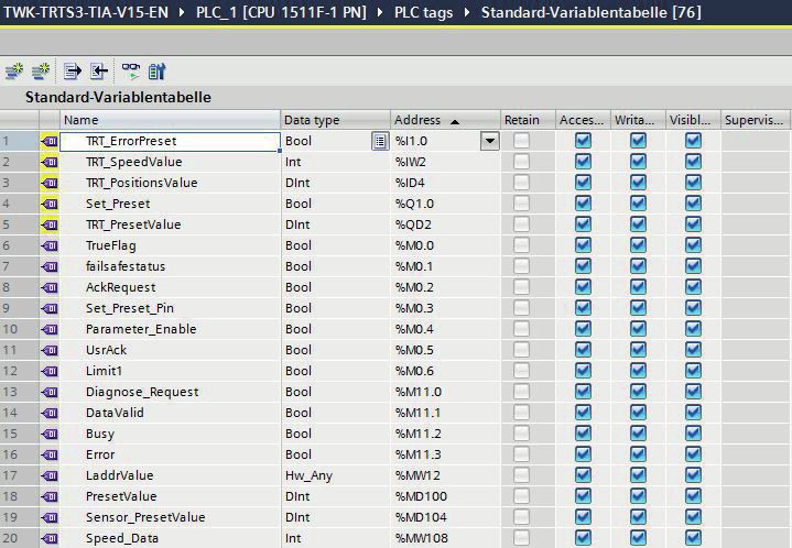
Datum: 20.02.2020 Seite 28 von 49 Document no. TRT 12846 NEProject planning with Simatic Step7 4.3 Application program 4.3.1 Remarks For a detailed documentation for project planning and programming of F programs refer to SIMATIC S7 Distribut- ed Safety - Project Planning and Programming, Programming and Operating Manual (A5E00109536-03) /7/ and SIMATIC S7 Distributed Safety Getting Started /8/ respectivly SIMATIC Safety - Project Planning and Program- ming /9/ und SIMATIC Safety Getting Started /10/ when using Safety Advance in the TIA-Portal. 4.3.2 F-Peripherie-DB On translation of the hardware configuration, an F periphery DB is generated for the absolulute encoder, as for each other Profisafe subscriber. The automatically generated name consists of the I/O address and the module name. The F periphery DB contains the for the operation of the encoder necessary variables. It has the following appearance: (A detailed description can be found in the documentation mentioned above) Distributed Safety Safety Advance 4.3.3 Accessing the encoder in the F program Important for the fail safe operation of the encoder are: reintegration after communication or F periphery errors by the variables „ACK_REQ“ and "ACK_REI" or "ACK_GL", evaluation of the failsafe status by the variable "QBAD" and the evaluation of the diagnostic data by the variable "DIAG". All mentioned variables are provided by the F periphery DB. An example can be found in the following example program. The access to the I/O data of the encoder is different and depending on the output code of the encoder and on Datum: 20.02.2020 Seite 29 von 49 Document no. TRT 12846 NE
Project planning with Simatic Step7

the S7 software package. Because in Distributed Safety the use of double words in the safety program is prohi-
bited in this case, only word access to the 32 bit position and reference value is possible, that means the position
and the reference value are devided into 2 words each and the evalutation has to be done seperately. For this
use encoder with output code "R" and "W" are provided.
In the safety program of TIA Safety Advanced doublewords can be used now. Thus position and reference value
in data type DINT32 can be treated in the same way as in the standard program. For this use encoder with output
code "D" are provided. For a description of the data format see chapter 5.

4.3.4 Example program

The following example shows how to access the position and speed value as well as the F periphery DB of the
Profisafe absolute encoder in the safety programme. Setting a preset value and reading the diagnosis data is
also demonstrated.

Only the programming steps which refer to the TWK absolute encoder are shown here. Knowledge regarding the
programming and sequence of the failsafe S7 programme is assumed. As an introduction to failsafe program-
ming, we recommend „SIMATIC S7 Distributed Safety - Getting Started“ /8/ and „SIMATIC S7 Distributed Safety
– Project Planning and Programming“ /7/ respectively SIMATIC Safety - Project Planning and Programming /9/
and SIMATIC Safety Getting Started /10/ when using Safety Advance under TIA-Portal.

All program blocks of the following example can be found in the internet under www.twk.de. The following docu-
mentation was created with TIA Portal V15 incl. Safety Advance and a CPU115F-1PN.

Devices required to operate the example program

   •   F CPU with PROFINET interface
   •   Profisafe encoder TRT/S3 with output code "D" (see "remarks to the program" on the next page)
   •   Step7 as of V5.4 + S7 distributed safety as of version V5.4 or Step7 Professional V13 with Safety Advanced

Hardware structure of the example program

Datum: 20.02.2020		                                 Seite 30 von 49                     Document no. TRT 12846 NE
Project planning with Simatic Step7

Inputs and outputs used in the program

Remarks to the program
Access to the profisafe absolute encoder is carried out in a F programme module (here FB100), which must be
called up in a F-runtime group (F call-up module F CALL when using Distributed Safety). Calling the FB100 in
the F CALL is not described here.

When using Distributed Safety it should be noted that access to double words is not permitted (see chapter 4.3.3).
An example program for Distributed Safety is available on our homepage.The examples show how to carry out
the comparision between the position and the threshold values although the position value consists of two words
and the compare operation needs integer values.

The following listing contains only the for the handling of the encoder relevant part. Program blocks like F-CALL,
clock OBs or peripheral data blocks are not listed.

Datum: 20.02.2020		                                 Seite 31 von 49                   Document no. TRT 12846 NE
Project planning with Simatic Step7

OB1, NW 1 - 3: Load preset value, show F error messages with the DIAG byte

Datum: 20.02.2020		                         Seite 32 von 49                  Document no. TRT 12846 NE
Project planning with Simatic Step7

FB100, NW 1 - 3: Reading QBAD and Acknowledge

Datum: 20.02.2020		                     Seite 33 von 49   Document no. TRT 12846 NE
Project planning with Simatic Step7

FB100, NW 4 - 6: Set reference value

Datum: 20.02.2020		                    Seite 34 von 49   Document no. TRT 12846 NE
Project planning with Simatic Step7

FB100, NW 7 - 8: Accessing position and velocity

Datum: 20.02.2020		                          Seite 35 von 49   Document no. TRT 12846 NE
Project planning with Simatic Step7

Reading the diagnosis data

On occurrence of a PROFINET device diagnostic alarm, OB 82 is run through in S7. Amongst other aspects, the
trigger for the diagnostic alarm can be ascertained in this. The diagnostic data can then be read-out with SFB52
which has to be called in the cyclic program. The events which trigger a diagnostic alarm in the absolute encoder
can be found in Chapter 7.2.

The control system transfers the hardware identifier of the device which has transmitted the diagnostic alarm in
the local variable LADDR.

 OB 82: Evaluation of the local OB 82 data and initialisation of the read job

 OB 1, NW 4:     Calling the FB 1 to read the diagnostic data

Datum: 20.02.2020		                                Seite 36 von 49                    Document no. TRT 12846 NE
Project planning with Simatic Step7

FB 2: Reading the diagnostic data with the SFB52 RDREC

Datum: 20.02.2020		                        Seite 37 von 49   Document no. TRT 12846 NE
Project planning with Simatic Step7

Evaluation of a Profinet alarm

The SFB54 (RALRM) has to be called in an alarm OB. In the output ID it delivers the hardware identifier of the
device that has triggered the alarm. In the data block to which AINFO points amongst others the alarm number
can be read.

 OB 82: NW 4

Datum: 20.02.2020		                               Seite 38 von 49                  Document no. TRT 12846 NE
I/O data

5. I/O data

5.1 Overview

5.1.1 Output code R and W

Input data: Device -> Controler
 Octet 1       Octet 2       Octet 3       Octet 4     Octet 5     Octet 6      Octet 7   Octet 8    Octet 9   Octet 10   Octet 11 Octet 12
      status word                            position data                           velocity                      F input data

Output data: Controler -> Device
 Octet 1       Octet 2       Octet 3       Octet 4     Octet 5     Octet 6      Octet 7   Octet 8    Octet 9   Octet 10
     control word                            preset value                                     F output data

5.1.2 Output code D

Input data: Device -> Controler
 Octet 1       Octet 2       Octet 3       Octet 4     Octet 5     Octet 6      Octet 7   Octet 8    Octet 9   Octet 10   Octet 11 Octet 12
      status word                 velocity                             position data                               F input data

Output data: Controler -> Device
 Octet 1       Octet 2       Octet 3       Octet 4     Octet 5     Octet 6      Octet 7   Octet 8    Octet 9   Octet 10
     control word                            preset value                                     F output data

5.2 Status word

The status word contains error bits which can be interpreted by the application program of the PLC.

               Octet 1                               Octet 2
 7     6   5    4   3    2    1   0    7     6   5    4   3    2   1    0
15 14 13 12 11 10 9               8    7     6   5    4   3    2   1    0

                         16 bit status word

     Bit       Name                                  Remarks/remedy
     0         Error_Preset                          Error during preset setting
                                                     - the preset value has to be in the range of 0 ... total number of steps -1
                                                     - set the preset value only during standstill of the shaft
                                                     - switch on scaling
 1 - 15 not used

5.3 Position data

The position value is output as a 2x 16 bit signed integer (output code R and W) or 1x 32 bit signed integer value
(output code D) in Motorola format (Big Endian). The factory setting of the resolution of the position value is 4096
respectively 8192 steps / turn. When using devices with output code R and D it can be adjusted via the parame-
terization. For output code W it is fixed to the maximum value.

Datum: 20.02.2020		                                                         Seite 39 von 49                       Document no. TRT 12846 NE
I/O data
5.3.1 Data format coding R
Octet 3 Octet 4 Octet 5 Octet 6
7 6 5 4 3 2 1 0 7 6 5 4 3 2 1 0 7 6 5 4 3 2 1 0 7 6 5 4 3 2 1 0
31 30 29 28 27 26 25 24 23 22 21 20 19 18 17 16 15 14 13 12 11 10 9 8 7 6 5 4 3 2 1 0
0 0 0 0 0 0 0 0 0 0 0 0 0 0 0 0 0 0 0 0 position value* (singleturn)
0 0 0 0 0 0 0 0 position value* (high) position value (low)
* At 12 bit resolution. With higher resolution correspondingly longer.
5.3.2. Data format coding W
The rotary encoders with code type W (TRTxx-xxxxxxxW4096S3xTxx) reveal deviating position and preset value
representation. In these models, the number of revolutions (multiturn part) is output in the first word and the steps
of the single-turn part in the second word
Octet 3 Octet 4 Octet 5 Octet 6
7 6 5 4 3 2 1 0 7 6 5 4 3 2 1 0 7 6 5 4 3 2 1 0 7 6 5 4 3 2 1 0
31 30 29 28 27 26 25 24 23 22 21 20 19 18 17 16 15 14 13 12 11 10 9 8 7 6 5 4 3 2 1 0
0 0 0 0 number of turns 0 0 0 0 steps*
* At 12 bit resolution. With higher resolution correspondingly longer.
5.3.3 Data format coding D
Encoder with the output code D (TRTxx-xxxxxxxD4096S3xTxx) provide a position- und preset representation as
double word (Integer32).
Octet 5 Octet 6 Octet 7 Octet 8
7 6 5 4 3 2 1 0 7 6 5 4 3 2 1 0 7 6 5 4 3 2 1 0 7 6 5 4 3 2 1 0
31 30 29 28 27 26 25 24 23 22 21 20 19 18 17 16 15 14 13 12 11 10 9 8 7 6 5 4 3 2 1 0
0 0 0 0 0 0 0 0 0 0 0 0 0 0 0 0 0 0 0 0 position value* (singleturn)
0 0 0 0 0 0 0 0 position value* (multiturn)
* At 12 bit resolution. With higher resolution correspondingly longer.
5.4 Velocity
The velocity value is determined via the cyclically read-in of the position data. The dimension is steps per gating
time. The gating time (time interval for determining the change of position) is adjustable in the range of 10 - 1000
ms. The default value is 10 ms.
Coding R, W Octet 7 Octet 8
Coding D Octet 3 Octet 4
7 6 5 4 3 2 1 0 7 6 5 4 3 2 1 0
15 14 13 12 11 10 9 8 7 6 5 4 3 2 1 0
16 bit velocity
The speed value is output as a 16-bit signed integer value in Motorola format (Big-Endian). The following applies
Datum: 20.02.2020 Seite 40 von 49 Document no. TRT 12846 NEI/O data
to the prefix:
positive for increasing position
negative for decreasing position
The refresh rate of the velocity signal is independent from the selected gating time always 1ms.
The speed measurement resolution is independent of the resolution set for the position value (resolution parameter).
In devices with 12 or 13 bit resolution it is based on a resolution of 4096 otherwise on 65536 steps per revolution.
The steps/gating time unit can be converted to rpm as follows:
v x 60000 / t v = encoder output for speed value
u=
r t = gating time in ms
u = speed in rpm
r = resolution in steps (4096 or 65536)
5.5 F input data
The 4-byte F input data consist of the 1-byte F status and the 3-byte CRC checksum. Their content is defined
in the Profisafe profile /1/. The status of the F status bit must be evaluated in the F application programme (see
programme example in Chapter 4.3.4).
5.6 Control word
Octet 7 Octet 8
7 6 5 4 3 2 1 0 7 6 5 4 3 2 1 0
15 14 13 12 11 10 9 8 7 6 5 4 3 2 1 0
16 bit control word
Bit Name Meaning
0 Set_Preset The preset value is activated on the rising edge.
1 - 15 not used
5.7 Preset value (reference value)
In certain cases, setting the reference value is unavoidable in order to compare the machine position values and
the absolute position of the absolute encoder. The reference value is the position value which is displayed at the
reference point. The user must note that the reference value must lie within the range of 0 to (total number of
steps - 1). This particularly has to be taken into consideration when changing the total number of steps.
The set reference value (preset value) function can only be executed whilst the absolute encoder shaft
is stationary! Setting the reference value is only possible when scaling is switched on (see Chapter 6)!
The preset value is set in the cyclical I/O data traffic by transferring the preset value in the output bytes (octets
3 - 6) and subsequently (or simultaneously) setting bit 0 of the control word (octets 1 - 2).
Before setting the preset value, the i parameterization must be enabled with the F control bit iPar_EN. The rotary
encoder reports the completion of the process with the F status bit iPar_OK. If an error occurs on setting the
preset value, e.g. due to a rotating rotary encoder shaft, this is reported via status bit 0 in the status word. In both
cases, i.e. in the case of successful preset and in the event of an error, the iPar_EN bit must be reset. The rotary
encoder then resets its iPAR_OK to zero. (See programme example in Chapter 4.3.4.)
Datum: 20.02.2020 Seite 41 von 49 Document no. TRT 12846 NEI/O data
The preset value is taken over with the rising edge of bit 0 of the contorl word. An offset value is calculated (from
the current actual position and the reference value) by the absolute encoder in this case. This is stored in the ab-
solute encoder, where it is protected against zero voltage, with the result that the new position is correctly output
again even following voltage failure.
5.7.1 Data format coding R
Octet 3 Octet 4 Octet 5 Octet 6
7 6 5 4 3 2 1 0 7 6 5 4 3 2 1 0 7 6 5 4 3 2 1 0 7 6 5 4 3 2 1 0
31 30 29 28 27 26 25 24 23 22 21 20 19 18 17 16 15 14 13 12 11 10 9 8 7 6 5 4 3 2 1 0
0 0 0 0 0 0 0 0 0 0 0 0 0 0 0 0 0 0 0 0 preset value* (Singleturn)
0 0 0 0 0 0 0 0 preset value* preset value
* At 12 bit resolution. With higher resolution correspondingly longer.
5.7.2. Data format coding W
Octet 3 Octet 4 Octet 5 Octet 6
7 6 5 4 3 2 1 0 7 6 5 4 3 2 1 0 7 6 5 4 3 2 1 0 7 6 5 4 3 2 1 0
31 30 29 28 27 26 25 24 23 22 21 20 19 18 17 16 15 14 13 12 11 10 9 8 7 6 5 4 3 2 1 0
0 0 0 0 preset value number of turns 0 0 0 0 preset value steps*
* At 12 bit resolution. With higher resolution correspondingly longer.
5.7.3 Data format coding D
Octet 3 Octet 4 Octet 5 Octet 6
7 6 5 4 3 2 1 0 7 6 5 4 3 2 1 0 7 6 5 4 3 2 1 0 7 6 5 4 3 2 1 0
31 30 29 28 27 26 25 24 23 22 21 20 19 18 17 16 15 14 13 12 11 10 9 8 7 6 5 4 3 2 1 0
0 0 0 0 0 0 0 0 0 0 0 0 0 0 0 0 0 0 0 0 preset value* (Singleturn)
0 0 0 0 0 0 0 0 preset value*
* At 12 bit resolution. With higher resolution correspondingly longer.
5.8 F output data
The 4-byte F output data consist of 1 control byte and the 3-byte CRC checksum. Their content is defined in the
Profisafe profile /1/. The F control bits are made available by the F control system and must be implemented in
the F application program (see programme example Chapter 4.3.4).
Datum: 20.02.2020 Seite 42 von 49 Document no. TRT 12846 NEYou can also read