VICTORIAN SPEEDWAY COUNCIL INCORPORATED VSC 1200 JUNIOR SEDAN 2018-2021
←
→
Page content transcription
If your browser does not render page correctly, please read the page content below
VICTORIAN SPEEDWAY COUNCIL INCORPORATED
              VSC 1200 JUNIOR SEDAN 2018-2021

These Regulations and Specifications apply to all Owners, Driver’s, Pit
crews, Officials and Clubs engaged in the promotion, conducting,
competing and/or presentation of VSC Inc. Classes.

This book must be read in conjunction with VSC Inc. approved Special
Regulations and/or Notices issued by the VSC Inc. from time to time.
Ignorance of these Regulations and Specifications and Notices shall be
deemed as No Defense in regard to breaches and/or appeals of same.

Where there is a difference of opinion between the Scrutineer, Machine
Examiners, Officials, Owner/Driver in regard to the interpretations of
any specification or regulation within this book then that matter shall be
resolved by the VSC Inc. Technical Committee at the earliest available
opportunity.

If ‘IT’ is not in the book, inquire for prior clarification or approval
before construction or implementing.

GENERAL SPECIFICATIONS:

CONSTRUCTION
To be of professional standard. All materials used must be of good
quality.
Bolts are not to be used through structural tubing unless a welded
sleeve is provided.
All material sizes quoted are minimum unless a maximum is stated.
Definition of material:
CHS Circular Hollow Section
RHS Rectangular Hollow Section
WT Wall Thickness
OD Outside Diameter
AS 1163 G.200: Australia Standard 1163 for structural steel tubing
grade 200.

                                    1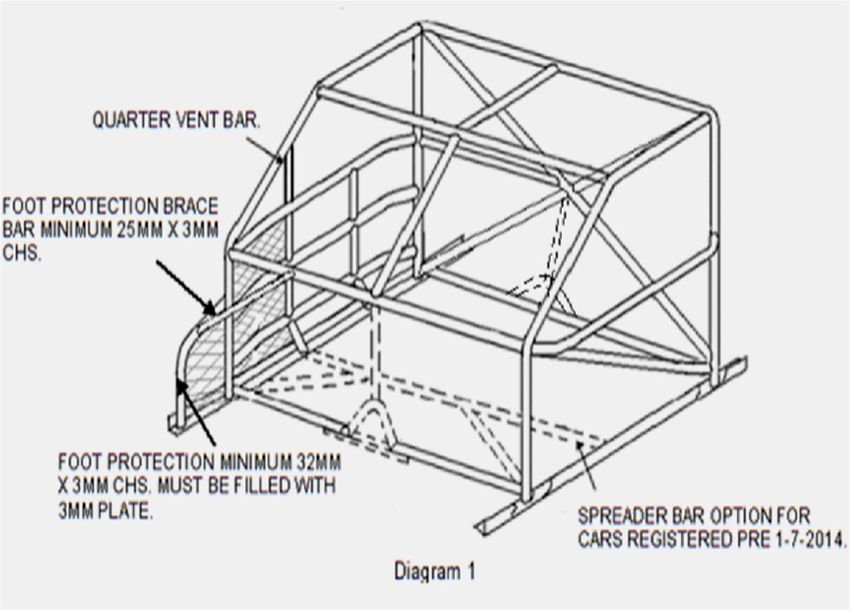
For clarity in printing Imperial sizes changed to Metric have been
rounded off the nearest full millimetre. These sizes will continue to be
accepted (i.e.: 1.25” = 31.75mm rounded to 32mm)

1. DRIVER SAFETY
All protective clothing and safety equipment must be used and/or worn
in the approved and accepted manner. Flame protection (suit) plus
thermal protections (underwear) equal driver protection.

PROTECTIVE CLOTHING
RACE SUIT:
Racing suit must meet minimum standard of either SFI 3.2A /1 or FIA
8856-2000 Suit to be snug fit at ankles, collar and cuffs. Must be
fastened at all times whilst in car. Suit to be in a clean and tidy
condition and free of holes or wear. The only IMPACT RACING safety
attire accepted is to have relevant SFI label with date of
manufacture 2009-2010 or later on label.
Two piece suits NOT PERMITTED.

No synthetic material to be worn against skin. (One way
communicator earpiece and lead allowed).
No jewellery to be worn.

UNDERWEAR:
 Full length underwear meeting minimum standard of either SFI 3.3, or
FIA 8856-2000, ‘MUST’ be worn by all drivers.
Approved underwear must be worn regardless of type of race suit.
Socks meeting minimum standard of either SFI 3.3, FIA 8856-2000.
‘MUST’ be worn by all drivers and passengers.
Socks must be higher than bottom cuff of under wear.

BOOTS, GLOVES, BALACLAVAS:
Boots, gloves and balaclavas are compulsory in all divisions and must
meet minimum standard of either SFI 3.3, or FIA 8856–2000.
Balaclava must cover the nose to prevent inhalation of flames and must
be long enough to fit inside of or cover the collar of the race suit.

Gloves must reach driving suit cuff. Gloves cannot be modified in any
way (e.g. Removing thumb).

                                    2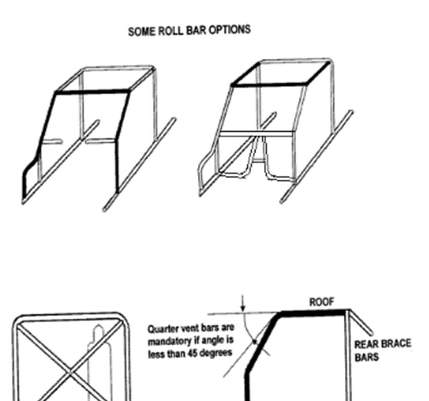
Boots must cover the ankles and be high enough to permit coverage by
the driving suit cuff.

HELMET:
Driver must wear approved and correctly fitting helmet. The helmet
must meet minimum standard AS 1698, Snell 2010, Snell 2015 or
ECE 22.05 (WITH ECE 22.05 LABELLS ON CHIN STRAP AND
HELMET. NOT HELMET ONLY) and pass inspection by the Scrutineer
or Technical Committee.
SFI suggested helmet life is four years. However if helmet has signs of
misuse, neglect or damage Scrutineer will note helmet serial number in
log book. If the helmet is found in use Chief Steward is to be notified
under Rule 6.2. Chin cups are not permitted. Inspection and approval
from Technical Committee to be obtained before painting or fitting non
oem stickers.

NECK BRACE (HORSE COLLAR)/ HEAD & NECK RESTRAINT
Approved head and neck restraints (e.g.: ‘Hans’ type devices) can be
used in lieu of a horse collar neck brace. A compulsory neck brace
must meet minimum standard of either SFI 3.3, or FIA 8856–2000.
Correctly fitted to suit the driver and helmet used, leaving a nominal
15mm gap to prevent leverage injuries. A horse collar neck brace is to
be high of density foam covered with Nomex, wool or similar fire
retardant material. Head and neck restraint devices must only be fitted
to the helmet by authorised installer as directed by the manufacturer
and must be SFI 38.1 or FIA 8858-2002 or FIA 8858-2010.
5 YEAR REPLACEMENT OR RECERTIFICATION FROM DATE OF
MANUFACTURE ON SFI 38.1 HEAD AND NECK RESTRAINTS.

EYE PROTECTION/GLASSES
Suitable eye protection must be worn i.e.: visor or goggles.
If a driver is required to wear optical glasses under any requirement for
licence under Vic Roads licensing and/or Medical Practitioner stipulates
that the optical glasses must be worn for reasons of VSC Inc. licensing,
then that driver must wear those glasses whilst competing and any
such glasses must be made of non-splintable type material.

SEAT AND SEAT BELTS
A ‘Purpose Built’ professional standard one-piece, fibreglass, approved
plastic / composite, steel or aluminium bucket type seat incorporating a
                                   3
substantial headrest, must be used. The use of mass produced,
competition-based alloy seats with lightening holes are permitted. E.g.
Kirkey/Butler. All holes are to be swaged as per manufacturers
specifications. The use of one-off type seats without holes is permitted
subject to VSC Technical Committee approval via Zone Scrutineer or
Technical Representative and endorsed in log book.
Minimum 50mm clearance Helmet to head plate/roll cage bars.
Concave seat to support back to minimum of TOP of shoulder height
and width.

Top of headrest to be at least 50mm above helmet to seat contact area
and to be within easy contact of helmet. Minimum width 150mm.
It is mandatory for all VSC cars to have a head rest brace of
minimum strength equivalent to 20mm x 20mm x 1.6mm RHS within
25mm of the back of the head rest, to stop the head rest moving back
beyond 25mm. If tubing is used end on, a plate of minimum 60mm x
60mm x 3mm is to be fitted to the end to stop it becoming a spear into
back of the head rest.

Seat base to be securely mounted to roll cage sub frame at a minimum
of two (2) points, using 8mm bolts and minimum 38mm diameter body
washers. Or to manufactures specifications IE: some plastic seats have
four (4) factory mounts in base.

Seat back to be securely braced to and attached to roll cage
approximately 75mm below shoulder height using a minimum of two
8mm bolts and minimum 38mm diameter body washers.

Lateral (sideways) support must be given to hips and above waist.
Front of seat under legs to be raised and rolled.
Seatbelts must be run through seat or links, not over top or sides.
Cut outs for belts to be suitably grommeted.

Seats may be padded and covered, the covering being securely
attached.
Maximum padding thickness 50mm.
Adjustable seats to be approved by VSC Inc Technical Committee via
Technical Committee Scrutineer or Technical Representative and
endorsed in logbook.

                                    4
An approved type racing harness must be fitted. MUST be SFI or FIA
approved. Five or six point 2 or 3 inch harness is mandatory and MUST
be a lever latch type, 2 inch crotch strap is permitted. SFI or FIA
approved head and neck restraint (eg: “Hans” type devices) seatbelts
permitted when restraint is used.
Harness to be fitted to manufacturer’s specifications or for
existing fitment the following guide lines. Seat belt bolts to be
minimum 10mm grade 8.8 with Nylok nuts only. (Standard
manufacturer’s bolts and nuts permitted ie: Simpson, G Force)
Maximum 300mm seat to seat belt mounting points
Seat belt mounting brackets minimum 3mm steel securely mounted to
roll cage or subframe or cross frames, not on sheet metal. Additional
seat belt mounting points may be needed for adjustable seats.
See ‘Installation of Restraint System’. [Fig. 1 and 2].
In order for the driver restraint system to be fully effective, considerable
thought must be given to the location of mounting points and to proper
installation. Many installations comply only with the letter of the rules
with no understanding of the needless injury to the driver.
The mounting points should be solid and should remain so even if this
vehicle is deformed due to an accident. The mounting points should
also not put undue strain or twist on the belt system hardware.
The lap belt should be positioned so it rides across the solid pelvic area
and not the soft stomach area or down on the thighs.
The shock absorbing ability to protect internal organs makes it the
preferred location for the belt. (See diagrams)
The shoulder harness should be mounted to prevent the driver from
moving upward, out of the seat, in the event of a rollover. The required
minimum distance from the top of the driver’s helmet to the top of the
roll bar does not leave much leeway for the shoulder harness to
prevent the helmet from striking the roof in the event of a rollover. The
shoulder harness is the major means of preventing injury in such an
accident.
Anti-Submarine straps serve two purposes.
5To secure the lap strap down across the drivers hips, so in the event of
an accident, it is not pulled up across the stomach by the shoulder
straps.
To prevent the driver from sliding forward and out of the harness [see
Fig.2(i) and Fig. 2(ii)]
For extra assurance a double strap anti submarine belt can be used
[see Fig.2(iii) and Fig.2(iv)]
When the driver is seated in a semi-reclining position a six point system
(two anti-submarine or crotch straps) is preferable. Most drivers find the
two anti-sub strap position more comfortable regardless of the type of
car.
In many instances, the anti-submarine straps are mounted much too far
forward of the seat. This practice could cause injury as the body can
slide partially out of the seat before being restrained when the strap
contacts the groin. It is much more practical to cut a slot in the seat
bottom so the anti-submarine strap can be anchored in line with the
chest.
Because of difference (often vast) in competition vehicles, “standard”
method of mounting is impractical.
Good judgement and common sense in inspecting restraint system
mounts is needed. Safety equipment is often neglected in favour of
performance equipment, but its proper operation when the need arises
is essential to survival.
The belts must be in good condition – no fraying, tears, fading.
etc.
6ONE WAY COMMUNICATOR:
The use of one-way communicator is compulsory.
Operating one-way communicator is to be presented at scrutineering.
7FIRE EXTINGUISHER:
On board fire extinguisher optional. It must be securely mounted and
be of the correct type for the fuel being used.
NUMBERS:
Numbers 1, 2 and 3 reserved for VSC State Title place getters. All
vehicles are to be presented for racing in a good condition, with
paintwork, sign writing and allocated numbers to be painted on the both
sides of body and a number to be visible when car viewed from the
front: i.e. roof number or sun visor.
Registered number and prefix are to be a contrasting colour and clear
of any sign writing, etc. Number will be 300mm minimum height x
75mm minimum width and prefix 150mm high. Cars must also have car
number front and rear of car, in a clearly visible position and to be
minimum 75 x 100mm in contrasting colours. Driver’s name/s to be on
roof above driver’s door or sunvisor minimum 50mm lettering.
ROOF NUMBER PLATE:
The roof identification number shall be a metal plate 30cm (300mm x
300mm) square with a 5cm 50mm right angle fold at the bottom where
2 holes, at 200mm centres shall be drilled to take 6mm bolts. The plate
shall be bolted vertically on the roof of the vehicle parallel with the side
of the car. (may also be V shaped)
The plate must be black background and white number/s in plain font
200mm high.
LICENSING:
Only VSC licensed persons may participate as a driver. Junior Drivers
to be aged 10 – 17 years.
INSURANCE:
Proof of approved speedway accident coverage is compulsory for
drivers.
Ambulance membership is compulsory for drivers.
ALCOHOL:
No alcohol/illicit drugs are to be consumed within twelve hours prior to
racing by driver. No alcohol permitted in the pit area. Drivers,
passengers or crews must not exceed .02% blood alcohol level at any
8time during scrutineering or race meeting, as per racing rules and
regulations.
TEK SCREWS:
No self-drilling screws (Tek Screws) permitted on external panels.
Diagram 3
WINDOW NET:
Window nets are mandatory.
Window Net lattice to be a minimum 19mm wide webbing with a
maximum hole size of 75mm x 75mm inside.
Window net to be securely attached to roll cage at top and bottom,
NOT car body and to cover 60% of side window area.
Not to be made of flammable material: i.e. Plastic.
Window net must be fixed top and bottom using a minimum 25mm x
3mm flat steel or 8mm steel rod through window net. Original window
net manufacturer supplied fitting hardware permitted.
The above design uses two push button seat belt buckles and the belts
tongues are welded to side roof bar
9Using either 25mm x 3mm minimum flat steel or 8mm minimum steel
rod, to be welded to rear of buckles.
Tubing at base of net must be removable and fixed with bonnet
lock pins.
No tek screws, pop rivets or cable ties permitted to fit window net.
CLASS SPECIFICATION VSC FOUR CYLINDER JUNIORS.
1. CARS:
A VSC FOUR CYLINDER JUNIOR class race car is built from a hard-
top sedan road car seating a minimum of four persons, as per the
compliance plate, and catalogued for sale in Australia, i.e. available
new, to the general public, through authorized Dealer sales and service
networks throughout Australia.
“Base model” body is used for silhouette and measurements. Forced
induction models not permitted in that form.
Four-wheel drive and/or four wheel steer models not permitted.
No new registration permitted on cars younger than eight years old.
2. ROLL CAGE:
See attached minimum roll cage diagram.
All bars in diagram are compulsory.
All cars must be constructed with a complete Roll Cage built to the
NASCAR design as used in other classes within the VSC Inc.
A head plate is compulsory for the driver and passenger and must be
welded on a minimum of three sides. The head plate to be 3mm flat
mild steel. Refer diagram. Bolt-in roof plate optional. Removable head
plate to be 5mm aluminium alloy or 3mm steel, 25mm x 3mm FMS strip
to be welded to main hoop, top windscreen bar, centre roof bar and
side roof bar. 10 of 50mm x 50mm x 3mm MS tags acceptable.
Plate to be mounted, from above, with 10 x 8mm diameter high tensile
bolts, 3 each side, 2 front, 2 rear. Heads of bolts to be downwards, i.e.
no projections.
The roll cage is to prevent the collapse of cabin area under impact.
Roll cage to enclose the driver/passenger, to be full width and full
height of the cabin area.
10The roll bars are to constitute a cage type framework; braced fore and
aft. The cage must extend from behind seats forward to the windscreen
area and incorporate protection for the feet.
a) All roll bar material must be good quality mild steel, minimum
AS 1163 Gr200. Minimum 38mm OD x 3mm W.T. CHS.
The use of any material other than low carbon steel for the
construction of roll cage must have V.S.C. Inc. Technical
Committee approval.
Aluminium based material not permitted.
b) The rear main hoop and main roll cage bars will each be made
of one continuous length of tubing, with smooth continuous
bends and no evidence of crimping, wall failure or significant
weakening. All bends to be made using a pipe bender with the
correct size former, Galvanized tubing or welding over threaded
tubing not permitted in any structural barwork. Water pipe
fittings or malleable fitting are not permitted. Roll cage built
using other than fusion welding techniques will not be accepted.
Gussets on welded joints may be required.
c) Main roll cage hoop to be within 50mm of sides of roof at
narrowest point. Top windscreen bar to be within 50mm of
windscreen at front roll cage leg on side elevation.
Front roll cage leg is to be within 50mm of windscreen opening
on side elevation and follow down the “A” pillar line at an angle
of no more than 45 degrees downwards from the horizontal.
The front leg will be no more than 250mm behind the original
door pillar at original top door line. Or 50mm in on the front
elevation at original top door line. Roll cage legs to be welded to
top of a subframe within 50mm of door pillars on front elevation.
Note for cars with sever rake of windscreen. If the angle of
roll cage ‘A’ pillar bar is less than 45 degrees down from roof
bar a quarter vent bar minimum 25mm OD x 3mm WT CHS is
necessary. Must be as close as practable to the first upright of
the NASCAR barwork and mounted in the top half of ‘A’ pillar
bar.
11Foot protection for roll cages with front leg more than 100mm
behind original door pillar, maximum 450mm measurement from
roll cage leg to forward section of foot protection bar and must
be filled with 3mm steel or 5mm aluminum plate, and must
cover all pedals when pedals are fully depressed.
Subframe to be tubular or angle section running fore and aft,
which is to be welded or bolted to the floor pan/sills using
minimum FOUR 12mm steel bolts through the subframe and
using 100mm x 100mm plates under the floor or four x 50mm
fillet welds. Distance from “B” Pillar to rear roll cage leg
maximum 150mm.
d) Subframe material:
e) Tubular minimum 38mm OD x 3mm WT CHS or 38mm x 38mm
x 3mm RHS.
f) Angle minimum 50mm x 50mm x 5mm.
g) Diagonal brace.
A minimum of a one piece diagonal brace, minimum 38mm OD
x 3mm WT CHS, will be fitted in the main roll cage hoop behind
the drivers head within 200mm from centre of bend. down onto
left hand rollcage leg directly above subframe brace. A
cruciform type brace may also be used minimum 32mm OD x
3mm WT CHS, cruciform mandatory for passenger. Drivers
side top down to left hand rollcage leg to remain one piece.
h) ADDITIONAL MINIMUM BARWORK: Minimum 38mm OD x
3mm WT CHS
Top windscreen bar.
Lower windscreen / dash bar.
Nascar door bars on drivers side: three horizontal sidebars
with only one bend at each end curved out to the door skin, are
to be placed between front and rear cage legs. Evenly spaced
between window sill and cage subframe. Top bar to be within
50mm of original top window sill.
Door pillar can be notched to accommodate barwork.
A minimum of two vertical spacer bars, evenly spaced between
12front and rear roll cage legs, are to be fitted between the cage
sub frame and top horizontal bar. Two door vehicles or vehicles
with excessive roll cage length between the front and rear legs
of the roll cage, must use three vertical bars and a quarter vent
bar fitted above the first vertical bar. Left side (passenger)
minimum two bars fitted between front & rear roll cage legs, one
must be horizontal within 50 mm at window sill height.
SUBFRAME CROSS BRACES.
Minimum of two sub frame cross braces at roll cage legs,
minimum either 38mm OD WT CHS or 35mm x 35mm x 3mm
RHS.
Option for cars registered prior to 1-7-2014, front sub frame
cross brace ( spreader bar ) may be moved rearward no further
than the first vertical door bar or to a maximum 300mm from the
front roll cage leg (as per rollcage diagram), providing a
diagonal brace if fitted between spreader bar and front roll cage
legs on both sides.
If rear subframe cross brace is bent to clear tunnel a vertical bar
minimum 25mm x 3mm must be fitted above tunnel between
subframe cross brace and rear hoop diagonal brace or
cruciform.
Centre roof bar minimum 32 OD x 3mm WT CHS.
Centre windscreen bar minimum 25mm x 3mm WT CHS.
Rearward brace bars minimum 34mm x 3mm CHS, must be
attached to top rear of main hoop no more than 100mm from
centre of the bend. Down on to rear subframes.
i) FOOT PROTECTION must be used as per diagram 1, minimum
tube size 32mm x 3mm CHS with minimum height of 300mm
and brought forward as far as practicable and must cover all
pedals when pedals are fully depressed. Must be filled with
3mm steel. A mandatory foot protection brace bar of a minimum
25mm x 3mm chs fitted between the front top half of the foot
protection bar and bar work to the left on the driver`s side
(preferably the dash bar). Foot protection for rollcages with
front leg more than 100mm behind original door pillar,
13maximum 450mm measurement from roll cage leg to forward
section of foot protection bar and must be filled with 3mm plate,
and must cover all pedals when pedals are fully depressed.
If fully depressed pedals do not protrude past roll cage leg.
Foot protection bar is not compulsory.
An “ANTI SPEAR” deflector plate, 3mm or 5mm aluminium (not
to be lightened by drilling) to be fitted to drivers side, from floor
line to window sill bar, forward of the first vertical door bar to the
front leg of the roll cage and must be fitted outside of roll cage.
If not welded one piece door plates to be bolted on using a
minimum of 6 – 50mm x 50mm x 3mm or 55mm x 40mm x 6mm
steel tabs welded to nascar bars and bolted using 8mm high
tensile bolts with no protrusions. If individual pieces are used
then a minimum of 4 – 50mm x 50mm x 3mm 55mm x 40mm x
6mm steel tabs welded to nascar bars and bolted using 8mm
high tensile bolts to each piece with no protrusions.
A MESH SCREEN will be securely fitted to roll cage and/or metal body
in front of driver, using either weld, bolts or metal hose clamps,
covering the entire windscreen opening. Maximum mesh size 50mm x
50mm minimum gauge 3mm.
25mm x 25mm mesh may use minimum 2.5mm gauge wire.
HEAD PLATE:
A head plate is compulsory for driver and must be welded on a
minimum of three (3) sides. The head plate to be of 3mm flat mild
steel. (Refer diagram)
Bolt-in roof plate optional. Removable head plate to be 5mm
aluminium alloy or 3mm steel, 25mm x 3mm FMS strip to be
welded to main hoop, top windscreen bar, centre roof bar and
side roof bar. Or 10 of 50mm x 50mm x 3mm tags acceptable
for 5mm aluminum. Plate to be mounted from above with 10 x
8mm diameter high tensile bolts, 3 each side, 2 front, 2 rear.
Heads of bolts to be downwards, i.e. no projections.
14See attached minimum roll cage diagram 1.
ROLL CAGE DIAGRAM
ALL BARS IN THIS DIAGRAM ARE MANDITORY. BROKEN LINES REPRESENT
SPECIFIC AREAS COVERED IN BOOK.
1516
3. BODIES

  a) Race car is to use an original, complete, metal body with the
     suspension mounting points in original position.
  b) Pedal position must remain in original position. Except
     Accelerator pedal. Pedals may be extended. No second set of
     pedals to push on the first set of pedals.
  c) All unnecessary flammable material must be removed, e.g. door
     trims, floor coverings; attached sound deadening material
  d) All fittings such as door handles, visors, ornamental mouldings,
     body trim strips; wheel trims etc. must be removed. All die cast,
     brittle plastic and chrome must be removed from the vehicle and
     all holes in firewall must be covered.
  e) All window glass and lights must be removed. Instrument glass
     permitted.
  f) Front chassis rails forward of cross member must not be
     removed. May be repaired with maximum 1.6mm steel. Tie bar
     between front chassis rails maximum 50mm x 50mm x 2mm
     RHS
  g) The only panels which may be replaced with
     fibreglass/aluminium replica:- max 2mm thick. Under panel
     reinforcement plate not permitted. Doors, bonnet, boot, front
     guards, nose. If original doors fitted they must be securely
     bolted or welded shut. Replacement doors may use maximum
     25mm x 25mm x 3mm RHS between A and C pillar`s to mount
     top of replacement doors.
  h) Replacement panels must be securely fastened; self drilling
     (TEK) screws not to be used on outside of body.
  i) The only panels which may be removed: Radiator support
     panel, front guards and inner guard panels forward of front
     suspension mounts, roof inner panels ONLY at the points where
     interference with the rollcage occurs, dash panel. Seat brackets
     and other brackets on cabin floor.
  j) If front guards are removed must be replaced with fibreglass
     replica.
  k) Steel bonnets and boots must have a minimum of 2 x 12mm
     bonnet pins and 2 quick release lock pins at front and secured
     at back.
     Skeletonising not permitted on hinged panels within 50mm
     hinges.The hinged panel to be welded to the bonnet or boot
                                17
skin.
Fibreglass or aluminum front bonnet to have a minimum of 5 x
12mm bonnet pins and 5 quick release lock pins 3 front, 2 rear.
Rear fibreglass boot to have a minimum of 4 x 12mm bonnet
pins and 4 quick release lock pins 2 front, 2 rear. Quick release
lock pins 3mm min. to 6mm max.
Bonnet pins are to be in the bonnet not sides of mudguards.
l) Bonnet pins to be minimum 12mm maximum 16mm.
m) Heavy duty large reinforcing washers (min 30mm OD) to be
fitted to all fibreglass bonnet and boot pin holes or worn holes in
steel bonnets and boots.
n) No tek screws outside body.
o) Fiberglass rear quarter panels and/or roof may be fitted over
damaged original panels, but must be securely attached.
p) Subframe barwork forward and rearward of rollcage maximum
size 38mmOD x 3.2mmWT CHS.
q) Cars with flat top rear wheel arches, i.e. Daihatsu Charade may
remove wheel arches to a 50mm clearance around rear wheels
and replace with fiberglass copy of original silhouette of wheel
arches. Original inner and outer metal panels must be re welded
together if cut away.
r) Radiator core may form part or rear fire wall.
s) Front and rear stone trays or metal or fiberglass copy must be
fitted. Cars with OEM plastic bumper/stone trays must use
original or fiberglass copy.
t) Paintwork and Signwriting: All paintwork, signwriting and
numbers to be neat, attractive and of professional standard.
The name of the driver will appear on the roof over RH door or
on visor strip, in letters of a minimum of 50mm high.
Battery location to be indicated by BLUE Triangle (50mm x
50mm x 50mm) on the body, adjacent to the battery.
u) Fuel tap lever or switch to be marked indicating FUEL and the
positions ON/OFF.
18Kill Switch to be clearly marked, in contrast colour, for method
of operation e.g. DOWN/OFF.
v) All Bodywork, including any subsequent repair of race day
damage, shall be to a Tradesman-like standard and must permit
the vehicle to be presented in as near to original condition as
possible.
w) No towbars permitted.
x) Fuel tank area must be accessible for scrutineering.
y) Grille may be fabricated from maximum 1.6mm sheet metal,
fiberglass or plastic. Or minimum 25mm x 25mm mesh, with
maximum 5mm wire diameter. Multi-piece, or folds for
strengthening sheet metal grilles, brittle plastic, or die cast grille
and/or fittings not permitted.
z) Headlight and tail light apertures to be covered with fiberglass,
plastic or maximum 1.6mm thickness sheet metal.
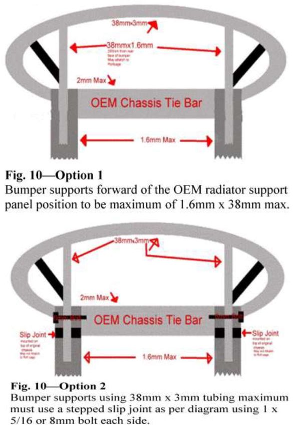
4. BUMPER BARS & OPTIONAL EXTERNAL BARWORK:
Original OEM type steel bumper bars NOT permitted, must be replaced
with maximum 38x3mm CHS. OEM plastic road car bumper bars
mandatory if factory fitted (no factory overrides or inserts) but must be
reinforced with max 38mm OD x 3.2mm WT CHS behind the bumper.
Bumper covers must be fitted with round head bolts aluminium rubbing
strip 40x3mm may be fitted between bolts to support bumper cover.
Bumper/s to be securely mounted in original position using supports of
a minimum of 100mm from the rear of the bumper tube. Maximum
support size, CHS 38mm x 3.2mm only, i.e. gussets are not to be used.
Bumpers are not to tie to under-guard barwork.
Bumpers are to remain hollow.
Corners and the ends of front and rear bumpers to be radius formed,
100mm minimum.
Maximum of four mounting points on front bumper bar.
Maximum of six mounting points on rear bumper bar.
Returns and bumpers to be flush fitting with the body, within 25mm.
Anti-hook-up bars from returns of Front and Rear bumpers to be
extended onto the stay bars or front subframe barwork.
FRONT bumper Maximum returns 300mm, Minimum 100mm.
19REAR only: Returns of rear bumper may be extended as a skid rail
against outside of body between bumper and wheel arch, and then
extend inward to the rear subframe or barwork.
REAR OVERRIDE BAR: An override bar may be used. Constructed of
maximum 25mm OD x 3.2mm WT it shall be no wider than the boot
panel and shall be mounted centrally on the bumper bar at no more
than four points, be VERTICAL and be max. 100mm high. Brace bars
are not to be used.
FRONT OVERRIDE BAR: An override bar may be used. Constructed
of CHS maximum 25mm OD x 3.2mm WT, Maximum 600mm long,
150mm high and mounted centrally on top of bumper at three points
only, i.e. it must have centre
mount.
Except for the bumper and bumper support bars, all barwork outside
the sub-frame skirts forward of the firewall, i.e. Under front guards, shall
be a maximum outside dimension of 25mm and a maximum wall
thickness of 1.6mm. Max 3 braces per side, one may be a vertical
upright attached to the bumper support. No other barwork to attach to
bumper bars or supports.
Shocker tower support bars to be mounted to rollcage / dash bar, bars
may form a crucifix.
Bars may run from shocker tower to front chassis rail, lower bars to run
along chassis rail top or bottom, inside or outside. Tie bar between
chassis rails to be maximum 50x50x2mm RHS.
No bar work forward of radiator support panel.
All bar work to be maximum 42mm OD x 3.2mm CHS or 40 x 40 x 3
RHS.
All bar work forward of windscreen to be below top of dash bar.
All bar work rear of rear rollcage hoop to be maximum 42mm OD x
3.2mm CHS or 40 x 40 x 3 RHS.
Front bumper bars that attach to front barwork must use
mountings as per figure 10 option 1 or 2.
2021
OPTIONAL RUB RAILS :
Rubbing rail between wheel arches permitted, maximum 25mm x
25mm x 3.2 W.T. RHS, to be securely attached against outside of body
by four (4) reasonable evenly spaced points, using M8 grade 8.8 or
M12 grade 4.6 coach bolts (round dome head). Through onto bar work
mounting points, ends of strips to be chamfered and filled in, mounting
bracket to be no larger than 25mm x 25mm x 3.2 RHS where
necessary (ie. onto rear bar work) any holes in bar work must be
sleeved and sleeves must be welded in place.
No other material may be placed inside rubbing strips, end mounts to
be within 50mm of ends.

                                  22
Minimum 4x 8mm 8.8 coach
bolts (cup heads) approx equal
spacings
Rub strips may be fitted with inner support strip maximum 25 x 25 x 3
RHS securely mounted at minimum 3 points to bar work, outer rubbing
rail to be bolted to inner strip with four bolts as above.
Inner support rail to be returned to bar work at each end.
.
MOUNTED TO MOUNTED TO
ROLLCAGE/BARWORK ROLLCAGE/BARWORK
INNER RAIL 25X25X3
MINIMUM 4 X 8MM 8.8 COACH
BOLTS (CUP HEADS) APPROX
EQUAL SPACINGS
5. SUSPENSION:
A VSC 1200 CYLINDER JUNIOR race car must use a complete metal
body with the suspension mounting points in original position and being
used.
23Only standard ‘Base model’ suspension components for year, make,
and model can be used.
Coil spring to remain coil spring, leaf spring to remain leaf spring.
Suspension components must attach directly to mounting points.
Suspension mounting points are defined as:-
Mounting points of suspension arm/wishbones either end; shock
absorber either end; struts either end; Springs either end; bars either
end.
All cars may use aftermarket castor/camber adjuster kits.
Spring spacers allowed above coil springs.
Coilover shocks, air shocks, pump-up shocks or adjustable suspension
arms, panhard bars/watts links ect are not permitted.
All Arms, Rods, Struts, Spring Hangers and Sway Bars must remain
standard, and functioning as manufactured, as per Manufacturer, for
year, make and model and body type.
All cars may change shock absorbers and springs to aid handling.
Standard sealed replacement units only. No external
adjustment/adjusters. E.g. no external reservoir/canister type or
externally gas pressure adjustment, (e.g. increase/decrease gas
pressure).
No shock absorber is to have the capacity to be adjusted whilst both
ends are attached to the standard mountings.
Koni and Bilstein O.E.M. street replacement shock absorbers allowed.
No competition aftermarket derivatives. E.g. AFCO, Bilstein, Koni, Pro,
racing type etc.
Shock absorbers/strut inserts must be standard replacement listed in
the catalogue for the model and readily available from automotive parts
suppliers e.g. Repco, Auto Pro etc
Mounting ends to remain original.
24Fitment of Koni style shock absorbers – the top swaged section of the
OEM housing maybe
removed and a new insert fitted, with the insert bolted through the
bottom of strut.
A strut brace between front towers is permitted.
Lowering blocks not permitted on leaf springs.
6. STEERING: Quick release steering wheel is mandatory.
Original OEM standard steering for make, model and year only must be
used. Modifications to Steering: No quick steer or reduction units
allowed. Non-original steering column shaft only permitted.
Steering must be in sound condition.
No modifications permitted.
Steering joints to be split pinned as required.
Wire spoke or wood rim steering wheels not permitted.
Steering column to be securely mounted to the roll cage dash bar.
Hub of steering wheel to be padded with dense resilient foam and
covered.
Steering to remain original OEM lock to lock.
7. BRAKES:
Fully operational standard foot operated OEM brakes system for make
and model to be fitted and be effective at race speeds.
No adjustable brake systems permitted. Must be OEM.
No drilled or lightened disk rotors permitted.
8. ENGINE:
Carburetor equipped engine to be type and size for manufacture`s
“Base model” of registered series.
All engines to have provision for sealing of engine at race meeting
Engine to be maximum four cylinders reciprocating only.
Maximum capacity 1200cc rear wheel drive, 1100cc front wheel drive
or 1000cc overhead cam. OEM – Base Australian Model.
25Sports model, Rotary, Fuel Injected, Turbo-Charged or Super Charged
engines or any other performance modifications are not permitted.
All engines to be fitted with standard accessories IE: charging system,
ignition system, fuel pump, starting system, air cleaner etc.
Engine will be inspected on the basis that all parts used in/on all
engines must comply with the specifications/dimensions specified in
original manual produced by the manufacturer for the standard engine;
with the exceptions of listed permitted modifications.
Owner/driver is responsible to prove the above and produce
information when necessary to validate.
Engine to be of standard stroke. Block, crankshaft and conrods to be
OEM parts for engine model.
No balancing of any engine components or removal of any balance
shaft permitted.
No polishing or porting of any engine parts permitted.
Standard engine may be over-bored a maximum of .060”.
A standard cylinder head may be faced a maximum of .060”.
Interchangeable standard components permitted; cylinder head and
manifolds.
Absolutely no modifications permitted to engine block, cylinder head,
manifolds, or original carburettor. No adaptor plates or adaptor gaskets
etc permitted for fitment of any interchangeable or standard parts.
Maximum two-cylinder sleeves may be fitted to engine block.
Offset boring of bearings or cylinders or angle facing of block or head
surfaces prohibited.
Crankshaft to remain OEM standard for engine model, stroking, offset
grinding or fitting of other makes or specially built crankshafts not
permitted.
Conrods to remain OEM standard for engine model.
26Pistons to remain standard type, flat top pistons permitted. (Some
Charade pistons may protrude above block)
No machined, lightened, forged or racing pistons permitted.
Camshafts unrestricted.
Cam followers to remain as standard type; i.e. Hydraulic, Solid etc.
Standard style replacement or original camshaft drives may have multi
keyways, offset keys or offset dowel pins.
The use of performance parts in the valve train is prohibited. E.g.:
adjustable or variable camshaft drive gears, roller rockers, cam
followers etc.
No porting or polishing of head or manifolds permitted.
Angle facing of head surfaces prohibited.
Standard valves, port size and finishes only permitted.
No double valve springs permitted
Sumps may be baffled but must remain externally visually standard.
Standard unlightened OEM fly wheel only permitted.
Datsun 1200 may use OEM twin outlet exhaust manifold.
Minimum six millimetre cable, chain or solid mounts must be used to
hold engine in position.
Distributor is to only be complete standard OEM system for make and
model.
Standard mechanical advance and retard must be operating with
standard advance weights in use.
Complete OEM vacuum advance and retard must be fitted, vacuum
hose optional.
Only one standard OEM carburettor fitted in standard OEM position for
make and model permitted.
Choke butterfly/s and shaft may be removed, and adjustable main jets
are the only modifications allowed to carburettor.
27One (1) throttle return spring must be used on each carburettor throttle
shaft, inbuilt spring permitted.
All vehicles must use some form of engine bay mounted air filter.
No air cleaners or air intakes in cabin.
Standard fitment OEM base model air cleaner ducting only is permitted
before air cleaner element.
Only standard fitment OEM base model carburettor heat shield
permitted.
9. COOLING SYSTEM:
Cooling system may be modified.
All pipes, caps, header tanks and hoses in cabin to be ducted or lagged
with suitable material.
All radiator hoses to be of fabric reinforced material, plain moulded
rubber hoses not permitted. Radiator pipes to be of steel, aluminium or
copper tube, all hoses to be fitted with correct clamps.
Pressure relief radiator cap or tap to be fitted to top radiator tank to
release pressure before loosening or removing radiator cap.
Taps and overflow tubes to be fitted with hose to direct steam to
ground.
Press button radiator caps not permitted, Lever vent type caps
permitted.
Radiator may be mounted inside cabin provided that they are mounted
as low as possible in the rear of the vehicle behind rear rollcage hoop
and suitably isolated from the driver. The upper half of rear window
opening MUST NOT be obscured by the rear radiator, header tanks,
hoses or caps.
Radiator ducting shroud, if used, to be maximum of 600mm forward of
the radiator and must not obstruct more than half the rear window
height.
Radiator core may form part or rear fire wall.
Cabin mounted radiators must have BOTH tanks fully covered to
protect driver in event of a cap or tank blowing.
28Hoses to be as short as possible and fitted to radiator from rear side.
All radiator coolant pipes, hoses, header tanks and caps in cabin area
must be inside rollcage and barwork.
No electric water pumps permitted.
No radiator spray systems permitted.
Cabin mounted fans to have shroud or suitable guard.
10. BATTERY /ELECTRICS:
Battery must be securely mounted to and inside roll cage or rear bar
work (not to floor or bumper bar barwork) in a suitable cradle. All
batteries to be fully enclosed i.e. battery box. Marine type box
acceptable. Must have a steel angle frame that covers four (4) sides of
the battery top and bottom. Bottom frame to be securely mounted to
bar work. Angle to be a minimum 25mm x 25mm x 3mm steel. Frames
to be connected with a minimum two (2) 8 mm rods/bolts. It is
recommended four (4) bolts be used.
Battery maybe mounted in boot using mandatory top and bottom
frames, battery must be covered.
Battery NOT allowed in engine bay.
A blue triangle of 50mm x 50mm x 50mm to be placed on the outside of
the car to show the position of the battery.
Suitable grommets must be fitted where battery cable passes through
metal firewalls.
At the commencement of a meeting, car must be capable of starting
with starter motor.
Switches: Ignition switch and electrical fuel pump switch, if fitted, must
be grouped together and be clearly marked.
Electrical switches NOT to be mounted through the floor.
29All electrical items to be securely and properly fitted and insulated
It is recommended that rubber covering be placed over the battery and
the exposed metal of the cable terminals to reduce acid spillage and to
reduce chance of arcing if metal contacts battery in any incident.
EXAMPLE OF MANDATORY BATTERY CLAMP/HOLD DOWN
FRAME
FRAME 25 X25 X3MM ANGLE – Top and Bottom
11. KILL SWITCH:
An external kill switch of contrasting colour must be fitted to the middle
of the cowl panel forward of windscreen mesh, and be clearly marked
with ON/OFF and method of operation. The purpose of the kill switch is
to kill the engine, ignition and all electrical items. Type of fuel being
used to be marked at Kill Switch.
12. TRANSMISSION & DIFFERENTAL:
Automatic and manual transmissions permitted.
a) Gearbox, clutch and diff housing to remain OEM for make and
model. E.g.: Corolla must use Corolla diff housing.
Interchangeable ratios with no modifications permitted. All OEM
gears must be operational. Rear axle centre line to be in OEM
position for make and model.
b) Differential position and pinion angle to be OEM for make and
model. Differential must be locked.
30c) A scatter shield of 3mm steel / 5mm alloy min width 150mm to
be securely mounted to auto transmission / clutch bell housing
or inside / outside of floor tunnel as near as possible to engine
firewall. To extend from right floor to left floor. When an engine
is transverse (front wheel drive) the scatter shield must also
cover the rear 180 degrees of clutch housing or attach to fire
wall. So as to protect the driver and passengers limbs from a
‘clutch explosion’.
d) When using an Automatic a working gearshift activated inhibitor
switch must be used.
Floor shifts must have a knob fitted and a correctly fitting boot.
REAR AXLE BEARING RETAINING RINGS. A new retaining ring
must be fitted at replacement of bearing or axle. Ring must be an
interference fit with the axle, when in place the retaining ring is to be
tack welded to the axle using MIG or a small diameter low hydrogen
rod on low amperage.
FAILURE TO OBSERVE THIS PROCEDURE WILL INCUR A
PENALTY, ESPECIALLY IF AN AXLE IS DISLODGED.
13. TAILSHAFT:
Rear wheel drive tailshaft must be fitted with 360 degree hoops at the
front and rear.
Front hoop to be minimum 40mm x 5mm FMS, 6mm chain or 6mm wire
cable or equivalent, be round, no larger than twice the diameter of the
tailshaft, and be securely mounted approximately 150mm from the
universal joint. 6mm minimum chain securely mounted through the floor
can form lower part of hoop.
Rear hoop to be as above except that it may be elongated vertically to
permit suspension movement.
Full chain hoops permitted.
Two piece tail shaft to have two loops on each shaft.
14. EXHAUST:
31a) Mufflers must be securely fitted and the noise level must not
exceed 95 decibels or track requirements. All exhaust gases
are to be directed away from driver, passenger, fuel tanks and
tyres and finish behind rollcage.
b) Exhaust manifold to be OEM standard. No modifications
permitted to OEM manifold. All original casting marks and
finishes must be visable. Remainder of exhaust system must
comply with following specifications.
c) Exhaust systems to have not more than one outlet pipe, and not
protrude beyond body line.
d) If exhaust system is under floor, safety chains minimum 4mm
will be fitted to front and rear of pipes and secured to floor pan
or sub-frame, and must exit out behind the rollcage and be
securely mounted.
e) Internally ducted exhaust system may vent through the body not
higher than 100mm above the door sill panel, using a slip joint.
Exhaust ducting and insulation not to exceed 150mm above
tailshaft tunnel and be no closer than 50mm to exhaust. No
other sheeting allowed in cabin area.
f) The driver to be suitably insulated from exhaust system.
15. FUEL TANK AND FUEL SYSTEM:
Fuel tank area must be accessible for scrutineering
Only unleaded pump fuel commercially available to the general
public at a service station must be used
Type of fuel being used must be marked at kill switch, fuel tap and
on boot lid or parcel shelf near filler cap. Tank to be securely
mounted inside bar work in the boot area of the car, no further forward
than front of rear wheel arches. In a suitable metal cradle attached to
bar work (Option A modified sedan type) with a minimum clearance
of 150mm forward of the boot panel, or (Option B standard saloon
32type) mounted centrally between wheel arches with rear of tank no
further back than rear of wheel arches, and isolated from driver by a
metal firewall.
Mounting brackets are not to be welded to fuel tank. No aluminium
straps or fittings permitted to secure tank.
Fuel tank straps to be steel minimum 25mm x 3mm for tank
capacity of 30 litres or less.
a) Original fuel tank must be removed and replaced by a tank of
up to 30 litres. Fuel tank is to be isolated from driver by a
minimum .9mm metal firewall.
Area beneath tank may be cut out up to 25mm larger than tank
giving adequate ventilation and ensuring that spillage cannot
remain in vehicle.
Cars that have cross members across the boot floor pan area;
the drilling of multiple holes as large as possible under tank that
will allow spilt fuel to escape quickly is allowed. Cross member
not to be cut or drilled.
Unleaded fuel only to be used.
Pressurized fuel tank/s NOT permitted.
No Jerry cans permitted.
b) Filler cap to be a positive seal (not tapered thread), behind a
firewall and inside boot.
Levers on cam locked caps to be clipped.
Metal fuel tanks over 25 litres must be baffled. All joints to be
welded to a professional standard.
Fuel tanks to be constructed of min. 1.0mm steel or mm.
3.0mm.
Fuel pick up fittings (etc) to come from top or side of fuel tanks.
Side fittings to be protected from intrusion by barwork.
Commercially available competition type “plastic” and
aluminium tank permitted with side outlet.
Metal fuel filler rings on plastic fuel cells must be fitted with
earth strap to barwork or body.
33c) A flexible fuel line section must be fitted within 75mm of fuel
tank and engine, all fuel lines to be securely fixed in position.
Barbed fittings of the correct size must be used in conjunction
with screw type clamps when connection flexible fuel line.
(Genuine SAE R6 fittings and hose exempted).
Neoprene, reinforced plastic or “Black Fuel Line” may be used.
OEM type Bundy steel tubing may be used through the car or
under the car.
Flexible fuel lines can pass through the cabin area.
No aluminium fuel line between tank and engine.
High pressure lines are to use high pressure hose and fittings.
The fuel line to the engine must be fitted with a quick action
NON-LEAK fuel tap or valve, in working order.
The tap, actuator or switch is to be mounted within easy reach
of driver and crash crew, and clearly marked “FUEL” ON-OFF.
Solenoid valves or remote mounted fuel taps are permitted.
Tap, fuel line and gauge are the only parts of fuel system
allowed in cabin.
Return fuel line to have one way valve fitted near tank.
Tank vents to be fitted to top of tank, with an anti-spill one way
valve and exit thru boot floor if floor fitted.
d) Electric fuel pumps, fuel filters, fuel pressure taps not to be
mounted in cabin, must be mounted within barwork and electric
fuel pumps must be wired with an independent earth. The pump
MUST be controlled by the “KILL” switch.
e) Fuel lines MUST BE ISOLATED from electrical wiring.
f) Tank to be protected by substantial bar work on all sides.
FUEL PROTECTION: Cars with a fuel tank behind wheel arch must
have fuel protection bar work as in Option A Diagram 3.
FUEL PROTECTION BAR WORK. OPTION A.
All rear barwork behind main rollcage hoop to be a minimum 34mm OD
x 3mm WT CHS.
Tanks to be securely mounted in the boot area of the car, in a suitable
metal cradle attached to the bar work, with a minimum clearance of
34150mm forward of the lower rear end of the boot panel and 300 mm
minimum from side of vehicle and isolated from driver by a metal
firewall. Rear braces to be attached to top of roll cage rear hoop no
more than 200mm from outside of roll cage leg. Tank to be protected
by substantial bar work on all sides.
Rear fuel tank protection bar:
Bar must be constructed of minimum 38mm x 3mm CHS, or 40 x 40
3mm RHS and be 25mm clear all around tank, pump and filter,
projecting a line from the rear wheel centre to the bar. Bar is to prevent
side entry to tank by nose of another vehicle. Protection bar must be
25mm higher for tanks above lower bar work or 25mm lower than an
under slung tank and mounted as per diagram 3. Brace bars to be
minimum 25mm x 3mm CHS (Brace bars do not constitute Bumper
mountings.)
FUEL TANK PROTECION BARWORK OPTION A DIAGRAM 3
REAR FUEL TANK PROTECTION BAR; BARS FOR FUEL TANK
THAT ARE ABOVE OR BELOW REAR BAR WORK, BEHIND REAR
WHEEL ARCHES. (BELOW BAR WORK SHOWN).
35Cars with a fuel tank forward of rear of rear wheel arch must have
either fuel protection bar work as in Option A Diagram 3 or option
B Diagram 4.
Fuel Tank Protection barwork Option B
(Standard saloon type)
All fuel tank protection bar work to be a minimum 34mm OD x 3mm
W.T. CHS, maximum 42mm OD x 3mm WT CHS.
To be welded to rear roll cage hoop. Bar work may follow contours of
boot floor and may be attached by a maximum of four x 50mm fillet
welds to floor or two 12mm steel bolts through the boot floor not
chassis rail, using two 100mm x 100mm x 5mm steel plates or one
50mm x 50mm x 4mm steel angle (no wider than inside of rear wheel
arches) above floor, and 100mm x 100mm x 3mm steel plates under
the floor. Rear braces to be attached to top of roll cage rear hoop no
more than 200mm in from outside of roll cage leg. Lower bars to be no
wider than inside rear wheel arches. To be no closer than 150mm to
rear inner face of boot panel. One (1) pair of reward bars may be
crossed.
Bar may be joined by sandwich plates or sleeved-joins to be minimum
500mm from rear of roll cage. Sandwich plate size maximum 150mm
square, minimum thickness 5mm, using four (4) 10mm high tensile
bolts per join. Alternatively bars to be sleeved a minimum 150mm and
welded. Optional, extra protection barwork, maximum 200mm high as
per diagram.
36FUEL TANK PROTECTION BARWORK OPTION B DIAGRAM 4.
16. WHEELS & TYRES:
All wheels must be steel or alloy construction.
Correct matching open-ended nuts and washers must be used.
37Alloy or Mag wheels may be used, must be one piece
construction.
Maximum wheel width 155mm/ 6 inch inside beads.
Maximum rim diameter 13 inches.
Original OEM steel wheel centre’s may be fitted with 6-inch steel
Rims.
Wheels must be in good condition and free from cracks.
No custom-made wheel centres permitted.
Balance weights not allowed.
Wheel spacers allowed.
Wheels fitted with spacers must have wheel studs a minimum of 10mm
past outer face of wheel nut.
Wheel studs not to protrude past face of rim.
Wheel covers not permitted.
Maximum 155mm wide
Radial tyres for use on street registered cars under registration by Vic
Roads only may be used.
No soft compound re-tread tyres allowed.
38Maximum tyre width 185 series, minimum profile 60 series, maximum H
tyre speed rating.
Race & rally, ‘competition only’, racing tyres, any tyre listed on a
‘specialist’ tyre list including Hoosier, Mcreary, Sport - Khumo, some
mud and snow, and Cr6zz Avon competition tyres are not permitted to
be used.
Tyres must be in good condition. And OEM markings to be legible on
side wall (i.e. 185/60R13H or 155/75R13H)
RECAPS AND REGROVING ALLOWED.
If a tyre cannot be identified (recap, make or rating) they will be
deemed to be outside the specification.
17. WHEELBASE AND TRACK:
Wheelbase Original, within 1% ABSOLUTE.
Method of measuring wheelbase shall be; with each front wheel
pointing straight ahead. Measure distance from front axle centre to rear
axle centre on each side of vehicle. Add dimensions for left and right
and divide by 2, allowable tolerance is +/- 1%.
39Track to be standard plus 50mm for vehicle being used. This is the
maximum allowable measurement. Measured from centre of tyre to
centre of tyre at axle height, front and back of tyre then averaged.
18. BALLAST.
Absolutely no ballast of any kind permitted on or in any part of car or
tyres.
19. MIRRORS:
Mirrors NOT permitted.
20. PADDING:
All projections that may present a danger to the driver must be suitably
padded.
21. DIRECTION OF RACING:
Anti clockwise.
22. ENGINE INSPECTIONS:
Any competitor may have their motors inspected at any time, engine
inspection to be in accordance with Technical Committee direction.
Only VSC Inc registered seals to be recognised.
All engines to have provision for sealing of engine at race meeting (i.e.:
sump, timing cover and heads to block and manifolds to head).
23. DIMENSIONS:
TABLE 1. – ENGINE LIST FOR VEHICLE MODEL
STANDARD STANDARD
MAKE MODEL
BORE STROKE
DATSUN 1200, 120Y, Sunny 73.0mm 70.0mm
DAIHATSU Charade 76.0mm 73.0mm
FORD Escort MK 1 80.978mm 53.29mm
HOLDEN Torana 77.77mm 60.96mm
LEYLAND Mini 1100 64.588mm 83.72mm
SUZUKI Swift SA SF 74.0mm 77.0mm
TOYOTA Corolla 1200 75.0mm 66.0mm
40TABLE 2 – VALVE SIZES – maximum two (2) valves per cylinder
INTAKE VALVE EXHAUST VALVE
MAKE MODEL
SIZE SIZE
1200 35.0mm 29.0mm
DATSUN
120Y, Sunny 37.0 – 37.2mm 30.0 – 30.2mm
DAIHATSU Charade 36.0mm 33.0mm
FORD Escort MK 1 35.69 – 35.94mm 31.50 – 31.75mm
HOLDEN Torana 33.45 – 33.60mm 29.90 – 30.05mm
LEYLAND Mini 110 29.23 – 29.26mm 25.40 – 25.53mm
Swift SA 36.0mm 30.0mm
SUZUKI
Swift SF 35.0mm 28.0mm
TOYOTA Corolla 1200 36.0mm 29.0mm
TABLE 3 – CARBURETTOR LIST
MAKE MODEL CARBURETTOR PERMITTED – Venturi
Sizes
DATSUN 1200, 120Y, Sunny Primary 20mm, secondary 26mm.Twin
Barrel Down Draught Primary
DAIHATSU 1.0 Litre 3 Cylinder Primary 18mm, secondary 25mm. Twin
Barrel Down Draught
FORD Escort 100 MK1 Ford 1250 Single Barrel
HOLDEN Torana 70 Series CD 150 Zenith-Stromberg.
Single Throat down Draught
LEYLAND Mini 1100 engines 1-½” S.U
SUZUKI 1.0 Litre 3 Cyl Primary 18mm, secondary 25mm. Twin
Barrel Down Draught
TOYOTA 1200 3K Series Primary 21mm, secondary 25mm. Twin
Engine Barrel down Draught
41TABLE 4 – VEHICLE DIMENSIONS
Note: Listed measurements for the track includes the 50mm max. allowance.
DATSUN
FRONT REAR
MODEL WHEELBASE LENGTH WIDTH
TRACK TRACK
mm mm mm mm mm
Coupe
2300 1290 1295 3820 1515
1970-74
1200
Sedan
2300 1290 1295 3835 1515
1970-74
120Y
2340 1300 1295 3950 1545
1974-79
Sunny
2340 1380 1350 3940 1600
1979-81
DAIHATSU
FRONT REAR
MODEL WHEELBASE LENGTH WIDTH
TRACK TRACK
mm mm mm mm mm
1980
2300 1350 1330 3485 1510
-81
XTE
1981
2300 1350 1335 3510 1510
-83
1983
Charade
2320 1390 1360 3550 1550
CSCX
-85
1985
2320 1390 1360 3595 1550
-87
G100
2340 1435 1415 3680 1615
1987-
G200
2395 1435 1440 3750
1993-96
FORD
FRONT REAR
MODEL WHEELBASE LENGTH WIDTH
TRACK TRACK
mm mm mm mm mm
Escort MK
2400 1310 1330 3960 1590
1970-73
42HOLDEN
FRONT REAR
MODEL WHEELBASE LENGTH WIDTH
TRACK TRACK
mm mm mm mm mm
HB
2440 1345 1345 44090 1600
Torana
1967-69
LC, LJ
2433 1345 1345 4120 1600
1970-74
Disc Brake
2433 1360 1345 4120 1600
Model
LEYLAND MINI
FRONT REAR
MODEL WHEELBASE LENGTH WIDTH
TRACK TRACK
mm mm mm mm mm
1100
2030 1260 1240 3176 1410
1969-71
Clubman 1100
2030 1260 1240 3220 1410
1971-73
SUZUKI
FRONT REAR
MODEL WHEELBASE LENGTH WIDTH
TRACK TRACK
mm mm mm mm mm
SA
2245 1380 1350 3585 1530
1984-88
Swift
SF
2265 1415 1390 3745 1575
1988-
43TOYOTA – Corolla
FRONT REAR
MODEL WHEELBASE LENGTH WIDTH
TRACK TRACK
mm mm mm mm mm
KE20 Sedan
2335 1305 1295 3910 1535
1970-74
KE25 Coupe
2335 1305 1295 3910 1570
1970-74
KE30 Sedan
2370 1345 1335 3995 1570
1974-78
KE35
2370 1345 1335 3995 1570
1974-78
KE50 Lift Back
2370 1345 1335 4120 1600
1977-78
KE55 - May use body only
TYRE SPEED RATINGS
A1- A8 5-40 Km/h M 130 Km/h
B 50 Km/h N 140 Km/h
C 60 Km/h P 150 Km/h
D 65 Km/h Q 160 Km/h
E 70 Km/h R 170 Km/h
F 80 Km/h S 180 Km/h
G 90 Km/h T 190 Km/h
J 100 Km/h U 200 Km/h
K 110 Km/h H 210 Km/h
L 120 Km/h
No soft compound re-tread tyres allowed.
23. JUNIORS:
Minimum age for juniors is 10 years old.
Maximum age for juniors is 17 years old
At the time of applying for their licence.
24. SPECIFICATIONS:
Specifications current until 30 June 2021.
44COPY RIGHT.
All right reserved. No part of this book, including cover, specifications and
drawings maybe reproduced or transmitted in any form, by any means
(electronic, photocopying, recording or otherwise) without the written
permission of the Victorian Speedway Council Inc.
45You can also read