Volume 10, Issue 6, June 2021 - IJIRSET
←
→
Page content transcription
If your browser does not render page correctly, please read the page content below

Volume 10, Issue 6, June 2021
International Journal of Innovative Research in Science, Engineering and Technology (IJIRSET)

 | e-ISSN: 2319-8753, p-ISSN: 2320-6710| www.ijirset.com | Impact Factor: 7.512|

 ||Volume 10, Issue 6, June 2021||

 DOI:10.15680/IJIRSET.2021.1006041

 Simulation of Hybrid Electric Vehicle Battery
 by Using MATLAB-Simulink
 Prasad Raut1, Mohit Mehare2, Kartiket Kadu3, Manali Waghade 4, Vishal Bagade5,
 Prof D.A Shahakar6
U.G. Student, Department of Electrical Engineering, P R Pote Engineering College, Amravati, Maharashtra, India1,2,3,4,5
 Associate Professor, Department of Electrical Engineering, P R Pote Engineering College, Amravati,
 Maharashtra, India6

 ABSTRACT: Electric vehicle’s (EVs) are probable to be an choice to be an preferred mode of transportation for the
future as it has a excellent capacity to minimize the consumption of petroleum based and different excessive CO2
emitting transportations fuels. In this study, the aspects of the BEVs machine had been mentioned and a mannequin of
BEV on the MATLAB-Simulink platform used to be simulated. Moreover, the relevant electrical system components
as well as its corresponding equations for verification were identified. Furthermore, all simulation consequences have
been considered. This work may gives a basic for greater researches.

 I. INTRODUCTION

One of the best challenges that is going through the surroundings in the world is energy conservation. Many difficulties
is being facing by our global energy environment. Although no one is aware of precisely the future of the energy, we
nevertheless trust that transportation will play a predominant function in saving the future strength.

 Today, Electric Vehicles (EVs) are one of the technological development outcomes that have contributed proceed to
make contributions in order to make our lives simpler and safer. Because EVs not just use energy, however they
additionally produce, store, and transport electricity. That is what makes them an incredible choice for the traditional
fuel based vehicles. Moreover, they are greater reasonably priced and eco- pleasant in contrast with the typical motors
that use fuel or diesel gas due to the fact they have a reversible electricity storage system .
In this study, MATLAB-Simulink used to be used in order to layout the BEV elements and integrating the complete
system. Moreover, it used to simulate the BEV and its equations.
This paper mentioned the simulation of the BEV, its applicable electrical system aspects and its corresponding equation
for verification. In addition, it examines all simulation results. The BEV components are Transmission, Battery Charge
Controller, Driver Model, Driving Cycle, Electric motor and Longitudinal Vehicle Dynamic Model

 II. BATTERY ELECTRIC VEHICLE COMPONENTS

Transmission Model

The Transmission prototype controls the vehicle’s moving necessities for the duration of gear change. It shifts torque
from motor prototype and braking pressure into the front and rear traction forces from driver model. The inputs of the
longitudinal vehicle dynamic prototype are the two forces of the transmission outputs calculations, cell balancing, and
State of charge (SoC). Based on IRIZ battery, this prototype covers a easy battery pack. The condition of charge
(SOC) is calculated using the following equation :

IJIRSET © 2021 | An ISO 9001:2008 Certified Journal | 6089

International Journal of Innovative Research in Science, Engineering and Technology (IJIRSET)

 | e-ISSN: 2319-8753, p-ISSN: 2320-6710| www.ijirset.com | Impact Factor: 7.512|

 ||Volume 10, Issue 6, June 2021||

 DOI:10.15680/IJIRSET.2021.1006041

 1. Battery Pack
 It is composed of M modules linked in parallel; each module consists of N series-connected smaller
 factors referred as “cells”.

 ( + × × × ) i e
 dwM G/d t = + +
 (1)
 = 1 ∫ [i( )] ∙ [ ( )]

 (4)

 Where J is the rotor inertia of MG, m is the automobile mass, k is the transmission ratio, which is 0.256, τ is equals
 to 2.72 x 10⁻², R tire radius,
 Tire is the derivative of MG
 d MG/dt rotation speed, T is the torque developed by MG

 using MG, T is the torque developed at the output of Power Split Device (PSD), and T is the resistant torque
 PSD r

 with the formula.
 Where SOD is the condition of discharge, t is time, T is temperature, and i is current.
 2. State of Charge
 In percentage, it expresses the lasting capacity of battery that ought to affected by the temperature, the
 discharge speed and the battery’s life. As the following equation shows, the ratio between the residual charge
 present and the nominal volume is the SoC.

 B. Electric Motor Model
 It has a very important role in BEV. The following
 SoC= Q( )

 (5)

 motor structures are developed based on a DC motor .
 1. Motor Speed Control
 The speed of the motor can be calculated at different speed techniques voltage. It is an input into the motor
 manager as shown in the equation below:
 W = + (2)

 Where U is the representative curve approximates to a line, the motor speed control instruction voltage, a and
 b are the equation coefficient additionally varies as the motor load changes.
 2. Regenerative Braking
 Regenerative braking feature captures the rotating energy reduction of the automobile and then converts it
 as an electrical power in order to feed it return into the battery source.
 W= 1 ( + ℎ)
 2 (3)
 2

 Where Wc is Energy kept in the vehicle’s energy source, m is Total automobile mass, V is automobile speed, h is
 Maximum altitude change of the BEV, and ɳ c is Energy effectiveness of the power source.

 C. Battery Charge Controller Model
 This feature is accountable for the batteries longevity. Its significance is in using an powerful Battery
 Management System (BMS) in designing the BEV’s electric system. BMS displays battery voltage, current,

IJIRSET © 2021 | An ISO 9001:2008 Certified Journal | 6090
International Journal of Innovative Research in Science, Engineering and Technology (IJIRSET)

 | e-ISSN: 2319-8753, p-ISSN: 2320-6710| www.ijirset.com | Impact Factor: 7.512|

 ||Volume 10, Issue 6, June 2021||

 DOI:10.15680/IJIRSET.2021.1006041

 Where Q (t) is the ratio between the residual charge available, and Q nom is the nominal volume.

 D. Driving Cycle
 It is the automobile operation schedule that explains the terms of the speed and gear selection as a function
 of time during the simulation. Driving cycles NEDC Mode for small vehicle in the city was designated in order
 to test fuel economy and vehicle performance of the small automobiles inside cities.

 E. Driver Model
 Aiming to discover an suitable throttle and brake instructions by PI automobile, driver model considers the
 objective speed and the real speed. Simulating the function of the driver and the automobile is given by this
 model. To assure having the specific reference speed monitoring with the aid of the vehicle, a response control
 loop of a vehicle speed is used. Provided via electric motor the throttle command from the driver prototype is
 transferred into torque and made an input to the transmission model .

 F. Longitudinal Vehicle Dynamic Model
 The car, tires, roadway and riding system communication can be defined under the longitudinal vehicle
 dynamic model theory. There are three variables for the continuous condition of motion dynamics model of
 an electric car: Wheel slip in the longitudinal direction, speed vehicle center of gravity and wheel
 circumferential speed. Getting each of the acting forces in a vehicle direction is important in order to control
 its

 Where ( ) is the longitudinal slip of the

 driven wheel, VV, V k, is the electric
 automobile speed

 III. METHODOLOGY
 MATLAB-Simulink used to show the battery electric automobile components and integrating the entire
 system. Moreover, MATLAB-Simulink used to simulate the battery electric automobile and its respective
 equation for conformation.
 MATLAB is a technical computing language that integrates programming, calculation and visualization in
 one environment. It has been modified in order to solve engineering and scientific issues and it is used now in
 many different fields. MATLAB has a powerful and big graphic toolbox that allows the user to work in an easy
 and easy environment.

IJIRSET © 2021 | An ISO 9001:2008 Certified Journal | 6091
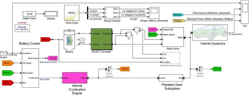
International Journal of Innovative Research in Science, Engineering and Technology (IJIRSET)

 | e-ISSN: 2319-8753, p-ISSN: 2320-6710| www.ijirset.com | Impact Factor: 7.512|

 ||Volume 10, Issue 6, June 2021||

 DOI:10.15680/IJIRSET.2021.1006041

 IV. TECHNICAL SPECIFICATIONS
 For this study we are using technical structure of PROTON IRIZ Car (BEV). Proton IRIZ is made in
 Malaysia. Table I shows the configuration.

 V. SIMULATION OF BATTERY ELECTRIC VEHICLE
 All mathematical equations that apply each part in the battery electric automobile simulation were selected
 to model the BEV. The simulation model includes six components: the transmission model, the electric motor
 model, the battery charge controller model, the driving cycle, the driver model and the longitudinal vehicle
 dynamics model as shown in Fig. 1.

 FIG 1.Simulation of Battery Electric Vehicle

IJIRSET © 2021 | An ISO 9001:2008 Certified Journal | 6092
International Journal of Innovative Research in Science, Engineering and Technology (IJIRSET)

 | e-ISSN: 2319-8753, p-ISSN: 2320-6710| www.ijirset.com | Impact Factor: 7.512|

 ||Volume 10, Issue 6, June 2021||

 DOI:10.15680/IJIRSET.2021.1006041

 VI. RESULT AND DISCUSSION
 As shown in Fig. 1 the BEV simulation model has been designed by the mathematical equations that are applied by
all subsystem blocks. Furthermore, the output shown in Fig. 2 and Fig. 3 represent the battery current, battery voltage,
battery state of charge and battery power.

Apparently, all the output visuals showed that the simulation is working in a good condition and also , New European
Driving Cycle (NEDC) was selected with the purpose of calculate the level of the fuel economy inside city and also
engine emission
In Fig. 2, the current, power and voltage of the battery are visible. As shown in the figure the curve of the battery
current follows the motor current dimension and the required torque graphs. Due to the increase in torque demand, we
can notice the increase of the battery current. Moreover, from the battery power graphs, power is drained from the
battery to the load while motoring then it returns to the battery during regeneration. The motor can run in a regular
motoring mode when the polarity of the voltage and the current are same. However, when the motor converted to
regenerative braking mode (generator), the current changes to negative and the power flows in the opposite direction.
Battery state of charge (SOC) is the ratio of the residual volume to the maximum volume. SOC for NEDC has a low
dead charge, which is best for fuel economy as shown in the Fig. 3.

 FIG. 2 Battery Voltage, Current, and Power

IJIRSET © 2021 | An ISO 9001:2008 Certified Journal | 6093
International Journal of Innovative Research in Science, Engineering and Technology (IJIRSET)

 | e-ISSN: 2319-8753, p-ISSN: 2320-6710| www.ijirset.com | Impact Factor: 7.512|

 ||Volume 10, Issue 6, June 2021||

 DOI:10.15680/IJIRSET.2021.1006041

 FIG. 3 Battery State of Charge

 VII. CONCLUSIONS

In this study, BEV and its components have been simulated with the intention of study the energy flow, efficiency and
performance. Best results for Battery current, power, State of charge, and voltage were shown in MATLAB-Simulink.
A lot of chances still ahead in order to create better BEV model that will be the basis for next future researches. With
the intension of finding the current, power, State of charge, and voltage for the battery and the exact component size,
and to minimize the use of energy, modeling and simulation are very important for automotive designers.

 ACKNOWLEDGEMENT

The researcher would like to thank the Head of Electrical & power Engineering, P R Pote college of Engineering &
Management Amravati (SGBAU university) for Guiding, mentoring and for providing every possible help.

 REFERENCES

1. J. Y. Yong, V. K. Ramachandaramurthy, K. M. Tan, and N. Mithulananthan, “A review on the state-of-the-art
 technologies of electric vehicle, its impacts and prospects,” Renew. Sustain. Energy Rev., vol. 49, pp. 365–385,
 2015.
2. Z. Chen, R. Xiong, and J. Cao, “Particle swarm optimization-based optimal power management of plug-in hybrid
 electric vehicles considering uncertain driving conditions,” Energy, vol. 96, pp. 197–208, 2016.
4. K. K., & Hat, M. K. (2015). SIMULATION BASED STUDY OF ELECTRIC VEHICLE PARAMETERS, 10(19),
 8541–8546.
5. Mohd, T. A. T., Hassan, M. K., & A. Aziz, W. (2015). Mathematical Modeling and Simulation of an Electric
 Vehicle. Journal of Mechanical Engineering and Sciences, 8(June), 1312– 1321.
 https://doi.org/10.15282jmes.8.2015.6.0128.
6. Meradji, M., Cecati, C., Wang, G., & Xu, D. (2016). Dynamic modeling and optimal control for hybrid electric
 vehicle drivetrain. In 2016 IEEE International Conference on Industrial Technology (ICIT) (pp. 1424–
 1429). IEEE. https://doi.org/10.1109/ICIT.2016.7474967.
7. Houcque, “‘Introduction to MATLAB for Engineering Students,’” Northwest. Univ. Version, no. August, pp. 3–
 43, 2005.
8. Reddy, G.N. 2012. A MATLAB-based tool for EV design. In: 2012 International Conference on Education and e-
 Learning Innovations (ICEELI).
9. L. Buccolini, A. Ricci, C. Scavongelli, G. DeMaso-Gentile, S. Orcioni, and M. Conti, “Battery Management
 System (BMS) simulation environment for electric vehicles,” in 2016 IEEE 16th International Conference on
 Environment and Electrical Engineering (EEEIC), 2016, pp. 1–6.
10. Zhou Bing, Jiang Qinghua, Yang Yi, & Wang Jisheng. (2010). Analysis of energy consumption and powertrain
 parameters

IJIRSET © 2021 | An ISO 9001:2008 Certified Journal | 6094
You can also read