VORTECH ENGINE BELT DRIVE SUPERCHARGER KIT INSTALLATION MANUAL
←
→
Page content transcription
If your browser does not render page correctly, please read the page content below
HOLDEN COMMODORE VF V6
                            SIDI 3.6L (2013-2017)

                       VORTECH ENGINE BELT DRIVE
                           SUPERCHARGER KIT
                         INSTALLATION MANUAL

                      For any further technical information contact:

                        Centrifugal Air Pumps Australia Pty Ltd
                          20 Verrall Cres, Berri SA 5343, Australia
                              Email sales@capadrift.com.au
                        Phone 08 8582 3499 (Intl. +61 8 8582 3499)

VF6SC-MANUAL – V1.0                  Printed 13 February 2020          - 0-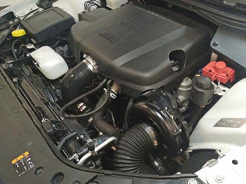
INTRODUCTION
Congratulations on selecting the best performing and best backed automotive supercharger
available today. Before beginning this installation please read this instruction booklet
thoroughly.

CAPA Supercharger Systems are a performance improving device. This product is intended for use
on healthy and well maintained engines. Installation on a worn-out or damaged engine is not
recommended and may result in failure of the engine and or the supercharger. CAPA IS NOT
RESPONSIBLE FOR ANY DAMAGES RESULTING FROM THE USE OF THIS KIT.

For best performance and durability please take note of the following key points:

1.      Use minimum of 96-98 RON unleaded fuel
2.      The engine must have stock compression ratio.
3.      If the motor has been modified in any way, check with CAPA prior to installation.
4.      Change your oil and oil filter. Refill with the best synthetic oil available.
5.      Check that all components of the ignition system are in top condition.
6.      Cold Starts - never race your engine when your engine is cold. Allow water temperature to
        rise up to operating range before driving above 2500 r.p.m. Engine damage may result in
        high r.p.m. and boost conditions when cold.
7.      Always listen for signs of deterioration (pinging) and discontinue hard use (no boost) until
        the problem is resolved.
8.      Change oil and oil filter every 5,000km. OVER FILL OIL BY 0.5 LITRE WHEN KIT IS FITTED.
9.      Always use an air-filter.
10.     Never strike the supercharger pulley with a hammer or other tools. (Evidence of such force
        will void warranty).
11.     Retention belt after 500-600km, if not sooner, because the belt will stretch during initial
        brake in period. Tighten belt only enough to stop slippage (the belt must still have some
        flex), over tension of the belt is the cause of input bearing failure
12.     Never over-rev supercharger. Internal step up on a Vortech V-3 Supercharger is 1.0 to 3.60.
        Impeller speed must not exceed 50,000r.p.m (Sealed Vortech).

        Impeller speed calculated as below:

                                Vortech V-2 / V-3 Supercharger
           Crank Pulley Diameter     x 3.60 x Engine RPM = Impeller Speed
        Supercharger Pulley Diameter

13.     Never hold RPM on Rev Cut as this will cause damage to the Engine by detonation.

        NOTE: The reason for grooved belts to move over one or more grooves or come off
        completely is always due to an alignment problem. Misalignment can also be caused by
        over-tightening of the belt - which may damage the drive system.

VF6SC-MANUAL – V1.0                        Printed 13 February 2020                           - 1-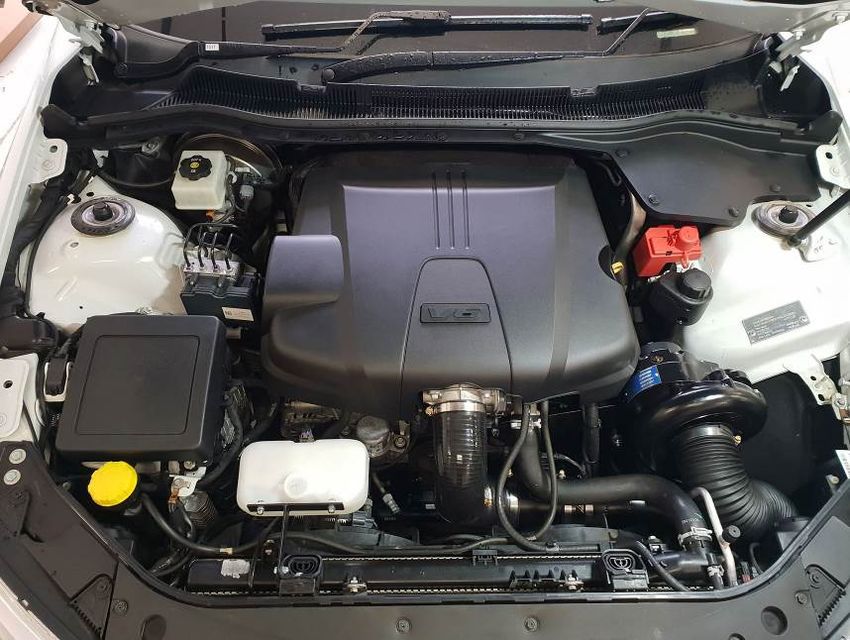
GLOSSARY
              COMPRESSOR HOUSING
              The housing, which makes up the enclosure portion of the compressor. Also
              referred to as the volute, scroll or snail.

              COMPRESSOR SURGE
              The phenomenon that occurs when the pressure ratio is too high for a given
              flow, or impeller speed. All centrifugal compressors can experience it. In
              automotive use it is most often found during decelerations when the engine
              speed is still high and the throttle is closed.

              DETONATION
              The uncontrolled rapid expansion or explosion of the air/fuel mixture in the
              combustion chamber.

              GAUGE PRESSURE
              The measure of pressure above atmospheric pressure.

              IMPELLER
              The bladed wheel inside the compressor housing that accelerates the air.

              INDUCER
              The air inlet portion of the compressor.

              NATURALLY ASPIRATED
              An engine without a supercharger.

              PRESSURE, BOOST
              The difference in pressure between barometric and intake manifold absolute
              pressure on a supercharged engine (read as gauge pressure).

              PRESSURE, ABSOLUTE
              The sum of gauge pressure and atmospheric pressure. One standard
                                                                      2
              atmosphere = 29.92 in. of mercury (Hg) = 14.696 lbs./in. (psi)

              PRESSURE RATIO
              Manifold absolute pressure divided by standard barometric pressure.
              P.R. = gauge pressure +
              atmospheric pressure
              absolute pressure

              STOICHIOMETRIC
              The correct chemical mixture of air and fuel to yield complete combustion.

VF6SC-MANUAL – V1.0                          Printed 13 February 2020                        - 2-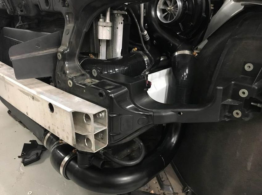
KITS PARTS LIST
                                                                       Quantity   Checked
SUPERCHARGER ASSEMBLY:
        Supercharger V3 SI CCW                                             1
        Vortech Oil Reservoir Bottle & Fitting                             1
        Vortech 6-Rib Supercharger pulley (3.48” / 3.6”)                   __
        Sealed Supercharger Oil – Installed in Supercharger                1
        Oil Drain Line – 300mm                                             1
        M6 Nyloc Nut and Washer                                            1
        ¾” x ¼” UNC Bolts, Spring and Flat Washer                          2
MOUNT / DRIVE SYSTEM:
        6PK 2567 RPM Belt - Non Intercooled – 3.6” Pulley                  __
        6PK 2540 RPM Belt - Intercooled – 3.48” Pulley                     __
        Supercharger Bracket                                               1
        Supercharger Bracket Brace                                         1
        M12 x 30mm Bolt, Flat & Spring Washer                              1
        M10 x 100mm Bolt, Flat & Spring Washer                             1
        1 ¼” x 5/16” UNC Cap Head Bolts, Flat and Spring Washers           5
        Pedestal “A”
        M8 x 140mm Bolt, Spring and Flat Washer                            1
        Machined Pedestal with Milled Cut Out – 79mm                       1
        Pedestal “B”
        M8 x 140mm Bolt, Spring and Flat Washer                            1
        Machined Pedestal – 79mm                                           1
        Pedestal “C”
        M12 x 150mm Bolt, Spring and Flat Washer                           1
        54mm Single Bearing Steel Idler Pulley w/ 12mm ID. Insert          1
        Machined Pedestal – 43mm                                           1
        Machined Pedestal – 21mm                                           1
        Pedestal “D”
        M12 x 90 Bolt & Nyloc Nut                                          1
        M12 Flat Washers                                                   2
        54mm Single Bearing Steel Idler Pulley w/ 12mm ID. Insert          1
        Machined Pedestal – 43mm                                           1

Parts List Continued on Next Page…

VF6SC-MANUAL – V1.0                         Printed 13 February 2020                   - 3-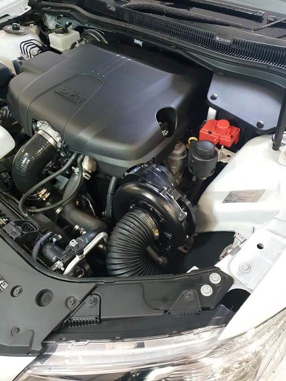
KITS PARTS LIST, CONTINUED
                                                                        Quantity   Checked
AIR INTAKE
        CAPA 3 ½”Air Filter w/ BOV Fitting in bottom                        1
        3 ½” Air Filter Hanger w/ PCV Fitting                               1
        550mm 3 ½” Intake Hose                                              1
        HS56 Hose Clamps                                                    3
AIR DISCHARGE - NON INTERCOOLED
        3” – 3 ½” Silicone 90 Degree Bends                                  2
        HS56 Hose Clamps                                                    2
        HS48 Hose Clamps                                                    2
        3 ½” MAF Pipe                                                       1
PCV HOSE FITMENT
        PCV Driver’s Side
        40mm x 10mm Fuel Hose                                               2
        One Way Valve                                                       1
        PCV Passenger’s Side
        1500mm x ½” Fuel Hose                                               1
BYPASS VALVE
        Plastic Bypass Valve                                                1
        300mm x 1” Hose (intercooled)                                       1
        1000mm x 1” Hose (non-intercooled)                                  1
        HS16 Hose Clamp                                                     1
        1500mm x 4mm Vac Hose (intercooled)                                 1
        500mm x 4mm Vac Hose (non-intercooled)                              1
        ½” to 3/16” Barb Tee Joiner                                         1
        100mm x ½” Fuel Hose                                                1
        Twin BOV Intercooled
        Plastic Bypass Valve                                                1
        Bypass Valve Filter                                                 1
        3/16” Barb Tee Joiner                                               1
        100mm x 4mm Vac Hose                                                1

Parts List Continued on Next Page…

VF6SC-MANUAL – V1.0                          Printed 13 February 2020                   - 4-
KITS PARTS LIST, CONTINUED
                                                                                   Quantity                  Checked
INTERCOOLER KIT
        Intercooler 2 ½” top – 2 ¾” bottom outlets                                       1
        LH Side Cooler Bracket                                                           1
        RH Side Cooler Bracket                                                           1
        M6 x 16mm Bolt, Spring and Flat Washers                                          4
        M6 x 25mm Bolt, Spring and Flat Washers                                          4
        Bottom Intercooler Pipe                                                          1
        Bypass Valve Grommet                                                             2
        2 ¾” Silicone 45 Degree Joiner                                                   3
        HS44 Hose Clamps                                                                 6
        Top Intercooler Pipe w/ MAF Fitting                                              1
        2 ¾” to 2 ½” Silicone 90 Degree Joiner                                           1
        3 ½” to 3” Silicone 90 Degree Joiner                                             1
        3” Straight Silicone Joiner                                                      1
        HS48 Hose Clamps                                                                 3
        HS56 Hose Clamps                                                                 1
        HS44 Hose Clamps                                                                 2
        3” Aluminium Joiner Sleeve                                                       1
        2 ¾” Aluminium Joiner Sleeve                                                     1
        Medium Zip Ties                                                                  6
        Small Zip Ties                                                                   6
WASHER BOTTLE REPLACEMENT
        Washer Bottle                                                                    1
        Washer Bottle Bracket                                                            1
        M6 x 16mm Bolts, Nyloc Nuts                                                      3
        M6 Flat Washers                                                                  6
        Loom Extension                                                                   1
Misc. Parts
        2 Bar Map Sensor                                                      1
        Base Calibration Tune File – Contact sales@capadrift.com.au, Quote Invoice number to receive file.
                                      (Please note this is only a BASE file for reference and may need to be modified)

  Important before beginning installation, verify that all parts are included in the kit.
                Report any shortages or damaged parts immediately.

VF6SC-MANUAL – V1.0                           Printed 13 February 2020                                                   - 5-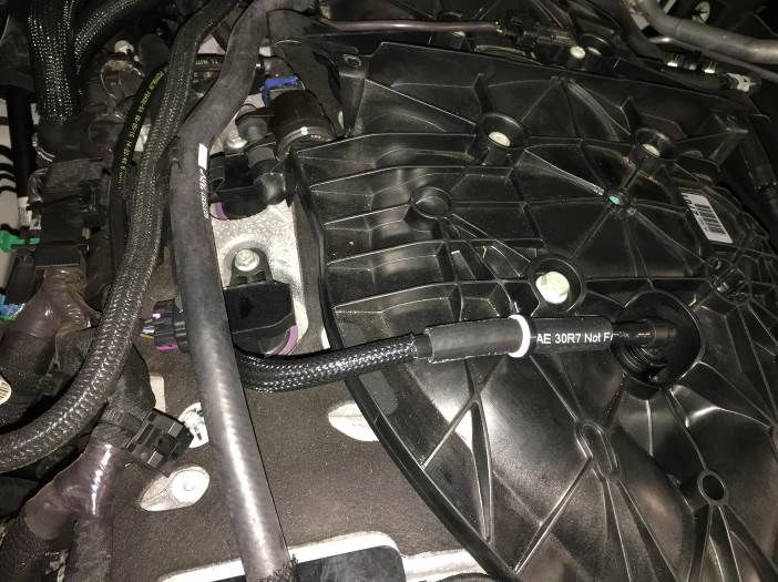
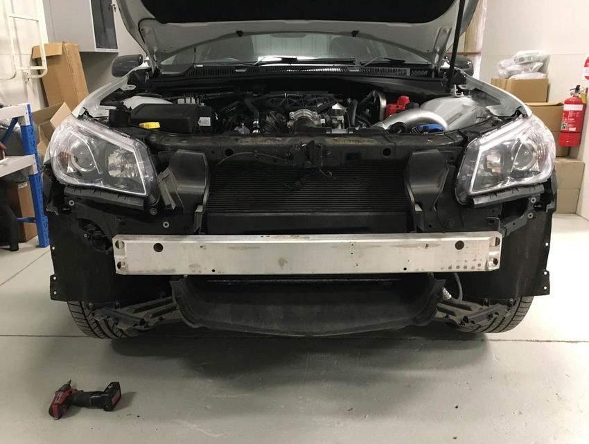
PREPARATION & PART REMOVAL
1.      Remove front bumper and lower cover

2.      Remove left hand headlamp

3.      Remove engine cover

4.      Remove airflow meter, ducting and complete airbox

5.      Remove Belt

VF6SC-MANUAL – V1.0                       Printed 13 February 2020   - 6-
INSTALLATION
1.      Supercharger Bracket Fitment Preparation
        Remove idler bracket from the side of the engine, disregard this part as it is no longer used.
        Picture A shows the M12 bolt that needs to be removed and Picture B shows the M10 bolt
        that needs to be removed from the side of the engine to remove the idler bracket. Also
        remove the M8 bolts on either side of the tensioner refer to picture A to see their locations.

         A                                                   B

2.      The supercharger bracket will be pre-assembled out of the box. Before fitting the bracket to
        the car mount the bracket onto the supercharger using 5x 1 ½” x 3/8” UNC cap head bolts.
        With the supercharger in place mount the assembly to the front of the engine. The three
        mounting bolts will align with the bolts removed previously.

VF6SC-MANUAL – V1.0                       Printed 13 February 2020                               - 7-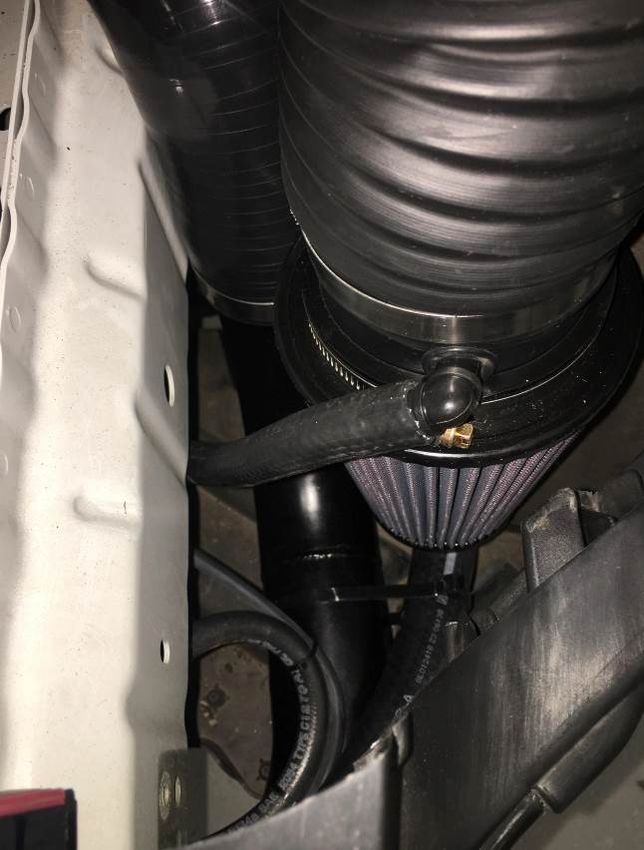
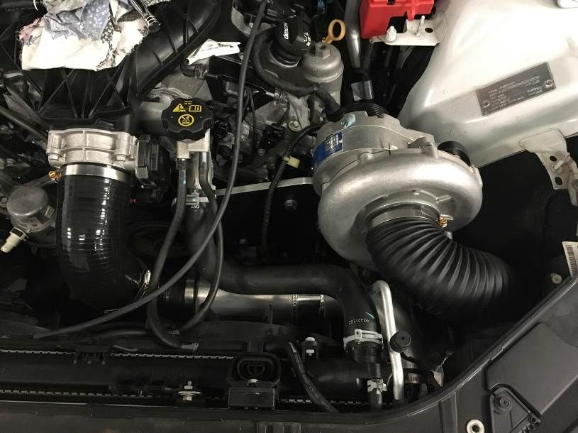
3.      At this stage mount the blow off valve to the volute as per photo and fit blow off valve hose
        and filter (if non-intercooled). Only half tighten the supercharger bracket to the engine as
        you will need to remove two of the pedestals to route the belt.

4.      With supercharger in position, fit oil header bottle to the top air box mount on the
        suspension tower, just under the positive battery jump point. Use 2x ¾” x ¼” UNC bolts and
        flat washers to fix mount to the bottle and 1x M6 nyloc nut and flat washer to fix mount to
        the suspension tower. Cut back and fit 5/8” oil hose from the supercharger to the barb on
        the bottom of the bottle. Tighten clamp. Make sure the tank has steel wool inside of the
        bottle.

VF6SC-MANUAL – V1.0                       Printed 13 February 2020                              - 8-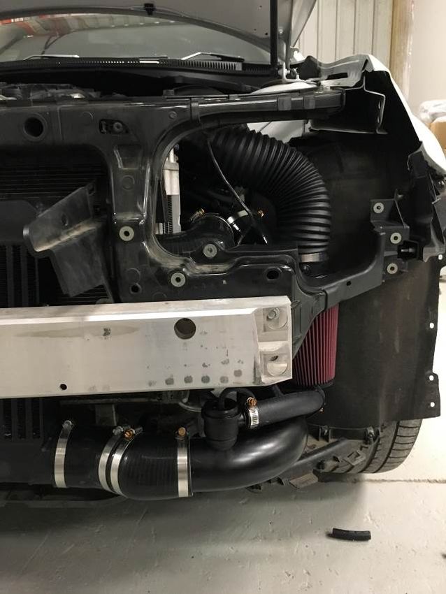
5.      With everything sitting in place route the belt as per the diagram, two pedestals will need to
        be removed, one at a time to route the belt correctly. Do not tension the belt in this step

                                                 6

6.     With the bracket still loose on the bolts and the belt in place, mount the bracket brace on
       the rear of the supercharger using the M12 bolt, washer and spring washer supplied. On the
       engine side of the brace remember to remount the bracket for the engine cover, the cover
       will be refitted later on. Use the M10 bolt supplied to mount brace to engine.

VF6SC-MANUAL – V1.0                       Printed 13 February 2020                              - 9-
7a. With everything now sitting in place tighten up the 3 pedestal bolts at the front of the
bracket. Take note the pedestal closest to the water pump has a machined section, make
sure it’s in the right location before tightening. Tighten the bracket brace next and keep the
engine cover bracket in the correct spot for later. Lastly in this step mount the belt around
all accessories and tension.
7b. If Intercooled disregard this step
Fit the 3.5” to 3.0” 90° bend to the throttle body then mount the airflow meter adapter pipe.
Mount the other 3.5” to 3.0” 90° onto supercharger as per photo. Once all aligned tighten
the 4 hose clamps supplied.
VF6SC-MANUAL – V1.0 Printed 13 February 2020 - 10-8. Fit 2.5 Bar Map sensor to the centre of the manifold. See pic below for location.
9. Drivers Side PCV
Using the hose and one way valve supplied cut and add in the hose in the centre of the
manifold. Make sure the valve allows air to travel into the manifold and not out into the
engine (preventing boost pressure to feed back to the rocker cover)
VF6SC-MANUAL – V1.0 Printed 13 February 2020 - 11-10. Passenger’s Side PCV
Early you would have removed this hose from the intake duct as you removed the air box
assembly in the preparation stages. Ref photo A., You now need the cut off the fitting and
disregard the fitting from the hose. Refer photo B. Slide the ½” hose provided onto the tube.
Route hose down into the inner guard ready for intake fitment later on. Ref photo C.
A B
C
VF6SC-MANUAL – V1.0 Printed 13 February 2020 - 12-11. Disconnect the vacuum line that routes to the brake booster from the passenger side of the
manifold. Add the 3/8” Tee Piece hose assembly as per the picture. Re fit the booster hose to
the other side of the tee and on the reduced add connect the 3/16” hose to the fitting.
Non Intercooled – Connect the 3/16” hose to the BOV on the front of the supercharger.
Intercooled – Route 3/16” hose down under the passenger side chassis rail ready for BOV
connection later in intercooler piping.
Intercooler Kit –
12. Washer Bottle
Mount washer bottle to bracket with two 6mm x 16mm bolts, nuts, flat & spring washers.
Drill a 6mm hole through the plastic radiator mounting bracket & fasten the bracket using
6mm x 16mm bolt, two flat washers & nut. Fit the original pump to the bottle and fit all
original hoses and supplied wiring loom extension.
VF6SC-MANUAL – V1.0 Printed 13 February 2020 - 13-13. With the front bar removed undo the 6x bolts holding the intrusion beam on from the front..
There are also some screws fastened in from the back that need to be accessed and
removed to complete the removal of the intrusion beam. Put factory washer bottle aside (no
longer needed.)
Pic of Intrusion Beam Assembly removed.
14. Remove intercooler and mount brackets from packaging as well as the 2 x M6 x 16mm Bolts
Using the intrusion beam as reference bolt the 2 brackets onto intercooler and tighten
VF6SC-MANUAL – V1.0 Printed 13 February 2020 - 14-15. Remove plastic infill panel and cut as per picture below, giving you 2 pieces.
On Passenger side Panel, trim the panel to allow it to sit into position over the intercooler
outlet
16. Position Intercooler and modified plastic infill panels onto intrusion beam and using the M6
x 20mm Bolts provided bolt up as an assembly
VF6SC-MANUAL – V1.0 Printed 13 February 2020 - 15-17. Refit Intrusion beam / Cooler Assembly back onto car, utilising factory bolts 18. Fit Lower intercooler pipe to cooler & SC outlet, using silicon joiner and clamps supplied. VF6SC-MANUAL – V1.0 Printed 13 February 2020 - 16-
19.     Prior to fitting intercooler top pipe, refit factory MAF electrics to top pipe. Using the 2.5”-
        2.75” Silicon 90° Elbow supplied fit to top i/cooler outlet..
        Fit 3” Silicon T/Body pipe onto Top pipe and push down into location. Fit to t/body and
        check fitment.. Adjust until happy with position then tight clamps up.
        Route MAF Loom down to MAF location and connect.

20.     Fit By-pass Valve into lower i/cooler pipe, NOTE, higher boost applications will have a 2nd
        bypass valve supplied. Ref to step 11, locating your Vacuum source for the bypass valves
        and connect.. (Pic below shows By-pass valve recirculating back into inlet)

VF6SC-MANUAL – V1.0                         Printed 13 February 2020                                 - 17-
21. Fit intake duct to inlet of S/C unit and clamp.
Fit Intake adaptor filter assembly as per pic below. Once in position connect By-pass valve
recirculation pipe.
Refer to Step 10 locating your passenger side breather hose, route around and connect to
fitting on inlet adaptor pipe.
VF6SC-MANUAL – V1.0 Printed 13 February 2020 - 18-22. Overview installation, once happy with install, tie / secure vacuum lines etc. to prevent
rubbing, clamps are tight
Position Engine cover back on motor and trim to relieve area that the s/c touches as per pics
below
23. Review s/c oil level instructions to ensure oil level is correct.
Check again once unit has been run in..
24. Time for tuning, contact CAPA for base calibration file (HP Tuners)
VF6SC-MANUAL – V1.0 Printed 13 February 2020 - 19-WARNING
1. DO NOT ATTEMPT TO OPERATE VEHICLE UNTIL ALL COMPONENTS ARE
INSTALLED AND COMPLETE. SUPERCHARGER KITS EXTRUDE A HUGE AMOUNT
OF HORSEPOWER FROM A STOCK ENGINE THEY ARE NOT INTENDED FOR
CONTINUOUS OR EXTREME PERIODS OF MAXIMUM POWER OUTPUT. IT IS NOT
OUR INTENTION TO CREATE RACE PROVEN HORSEPOWER BUT LEISURE
ENDURING SYSTEMS.
2. WARRANTY POLICY FOR 12 MONTHS, UNLIMITED KILOMETRES COVERS FAULTY
COMPONENTS PROVIDED IN SUPERCHARGER KIT. POLICY DOES NOT INCLUDE
LABOUR TO REPLACE FAULTY PARTS.
3. THE RESPONSIBILITY OF ADR COMPLIANCE AND INSURANCE FOR THIS KIT
FITTED TO A VEHICLE THAT IS ROAD REGISTERED AND DRIVEN IS THE
RESPONSIBILITY OF THE VEHICLE OWNER.
4. RESPONSIBILITY FOR CORRECT FITMENT OF THE KIT IS THE REPONSABILITY OF
THE FITTER.
5. DAMAGES TO VEHICLE OR SURROUNDS IS THE RESPONSIBILITY OF THE VEHICLE
OWNER. PROVIDED THE KIT FITMENT IS CORRECT, ACCORDING TO THIS
MANUAL.
GET OUT THERE & ENJOY...
VF6SC-MANUAL – V1.0 Printed 13 February 2020 - 20-You can also read