VWR INSTRUCTION MANUAL - Microscope - VWR International
←
→
Page content transcription
If your browser does not render page correctly, please read the page content below
VWR
Microscope			                series 384

                   INSTRUCTION MANUAL

                   Model                  European Catalogue Number
                 TL384 POL                         630-1936

Version:   1
Issued:    11, 03, 2015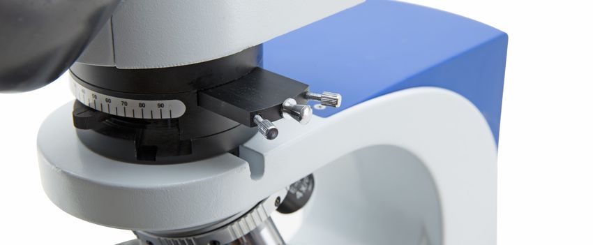
Legal Address of Manufacturer

Europe
VWR International bvba
Researchpark Haasrode 2020
Geldenaaksebaan 464
B-3001 Leuven
+ 32 16 385011
http://be.vwr.com

Country of origin: ITALY

                                 Table of Contents

Warning
Safety information
Package contents
Unpacking
Intended use
Symbols and conventions
Product specifications
Overview
Using the microscope
Troubleshooting
Repair and maintenance
User replaceable accessories and spare parts
Technical service
Warranty
Compliance with local laws and regulations
Disposal

                                       2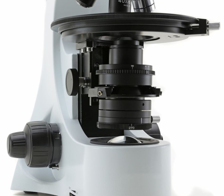
Warning
This microscope is a scientific precision instrument designed to last for many years with a minimum of main-
tenance. It is built to high optical and mechanical standards and to withstand daily use.
We remind you that this manual contains important information on safety and maintenance, and that it must
therefore be made accessible to the instrument users.
We decline any responsibility deriving from incorrect instrument use uses that does not comply with this
manual.

Safety Information

       Avoiding Electrical Shock

Before plugging in the power supply, make sure that the supplying voltage of your region matches with the
operation voltage of the equipment and that the lamp switch is in off position.

Users should observe all safety regulations of the region. The equipment has acquired the CE safety label.
However, users have full responsibility to use this equipment safely.
Please follow the guidelines below, and read this manual in its entirety to ensure safe operation of the unit.

Package Contents

DESCRIPTION                                                              QUANTITY
Microscope stand with head, focus and rotating stage                     1
WF10x/20 eyepiece                                                        2
Bertrand lens attachment                                                 1
Objective E-PLAN IOS POL 4x                                              1
Objective E-PLAN IOS POL 10x                                             1
Objective E-PLAN IOS POL 40x                                             1
Objective E-PLAN IOS POL 60x                                             1
Condenser with rotating polarizer                                        1
Retardation plates (lambda, lambda/4, quartz wedge)                      3
Allen wrench for objective centering                                     2
Power supply 6Vdc                                                        1
Dust cover                                                               1

                                                           3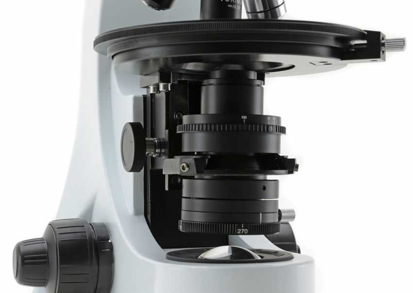
Unpacking
The microscope is housed in a moulded Styrofoam container. Remove the
tape from the edge of the container and lift the top half of the container. Take
care to ensure that the optical items (objectives and eyepieces) do not fall out
and get damaged. Using both hands (one around the neck and one around
the base), lift the microscope from the container and put it on a stable desk.

1. First of all remove all the components from the original package and store
   the box in a safe and dry place.

2. Place the main body of the microscope on a flat and sturdy surface.

Don’t connect the power supply cable at this stage.

3. Place the attachment with analyzer /Bertrand Lens onto the main body and
   turn the head locking screw (1).

4. Insert the optical head and lock the screw.

5. After removing the protection caps, fully insert both eyepieces.

                                                   4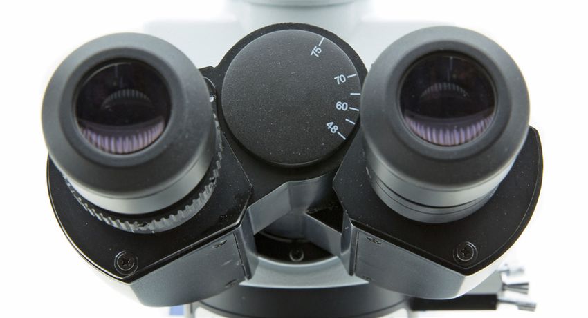
6. Connect the external power supply cable to the socket on the back of
the microscope.
If there is no need to install additional accessories,
the instrument is now ready for use.
Intended use
For research and teaching use only. Not intended for any animal or human therapeutic or diagnostic use.
Symbols and conventions
The following chart is an illustrated glossary of the symbols that are used in this manual.
CAUTION
This symbol indicates a potential risk and alerts you to proceed with
caution
Product specifications
Head Trinocular, 30° inclined, 360° rotating.
Eyepieces WF10X/20mm with cross hair.
Bertrand lens Swing-out type; centrable.
Polarizing
attachment 0°-90° rotating analyzer filter. Tint plates included: 1° order red (λ), λ/4, quartz wedge.
Nosepiece 4-positions with centering mechanism for all objectives.
Objectives E-PLAN IOS POL (Strain-free) 4x/0.10, 10x/0.25, 40x/0.65, 60x/0.80.
Focusing system Coaxial coarse and fine.
Stage 160mm dia.; 360° rotating with stop knob and 0.1° Vernier.
Condenser N.A. 1.25, with iris diaphragm, focusable and centrable. With rotating polarizer filter.
Illumination P-LED3, with manual brightness control.
Power supply External power supply: Input 100-240Vac 50-60Hz / Output 6Vdc 1A
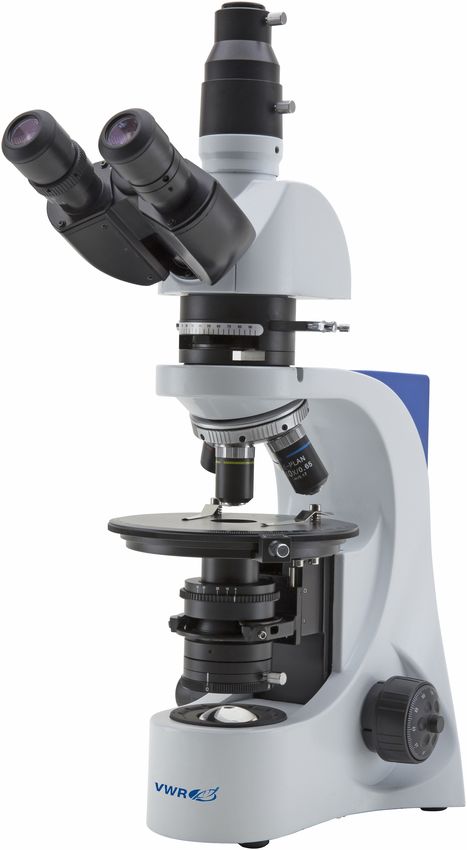
Overview
BERTRAND LENS
CENTERING SCREWS (10)
5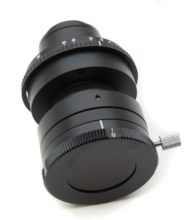
Overview
                                            PHOTO/VIDEO PORT

                      EYEPIECES (ONE
                      WITH CROSSLINE)

 DIOPTRIC
 ADJUSTMENT
 RING

                                                  BERTRAND LENS (13)

               ANALYZER
               ROTATION
               SCALE (8)
ANALYZER                                              RETARDATION PLATE (11)
INSERTION
LEVER (12)

              HOLES FOR NOSEPIECE
              CENTERING (7)

                        OBJECTIVE

   ROTATING STAGE

                                                               STAGE ROTATION
                                                               LOCK SCREW

        CONDENSER
        CENTERING
        SCREWS (2)

                    POLARIZER

                                        6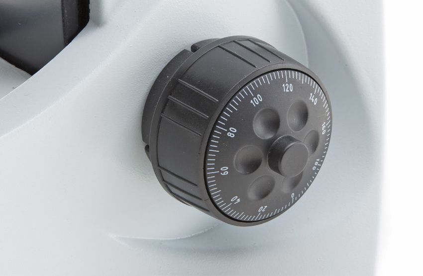
Using the microscope
Observation head
Loosen the lock-screw, turn the observation head to a comfortable position for observation, and then lock the
lock-screw.

Place the specimen on the stage
Lock the specimen slide on the mechanical stage using the slide clamp. Ensure that the specimen is centred
over the stage opening by adjusting the coaxial knobs of the stage.

Illumination system settings
The microscope is fitted with a white LED illuminator. Turn the brightness adjustment knob to a brightness
suitable for observation.

Adjust interpupillary distance
Hold the right and left parts of the observation head with both hands
and adjust the interpupillary distance by turning the two parts until
one circle of light can be seen.
The white dot (°) placed on the right eyepiece shows the set
interpupillary distance. Just remember this value to help on later
settings.

Focus tension adjustment
The tension of the coarse focusing knob is preset by factory.
To change the tension according to your preference, just rotate the
knob (3) clockwise in order to increase it.
Excessive tension could damage the mechanism of focus. A too
loosed tension causes the descent of the stage by gravity or a
sudden loss of focus. In this case, rotate the knob (3) to increase
the tension.

                                                                   TENSION    COARSE FOCUS      FINE FOCUS
                                                                   KNOB (3)

Diopter adjustment
Turn the dioptric adjustment ring on the left eyepiece halfway. Turn
the coarse focus knob in order to focus the slide with an objective
with low magnification. Adjust the fine focus knob until you obtain
a clear and defined picture observing with the right eye, and then
repeat the operation with the left dioptric compensation ring and the
left eye. When the image appears in focus, choose the necessary
objective with the revolving nosepiece.

                                                            7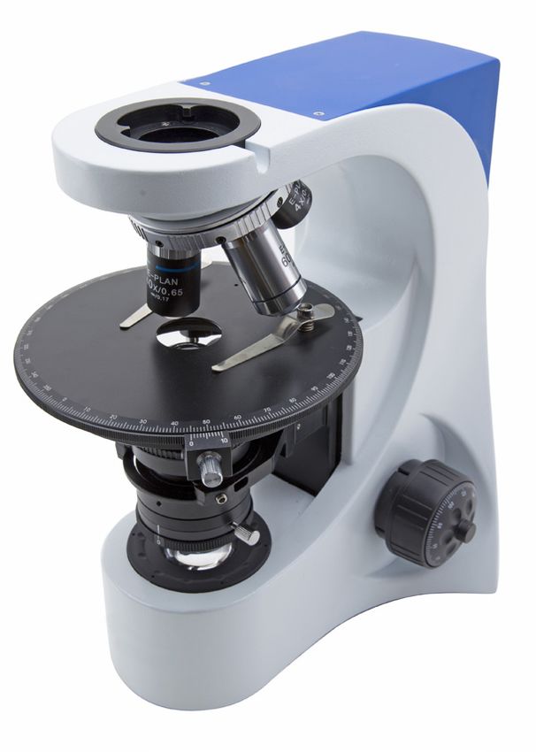
Condenser
 The condenser, placed below the stage, is equipped with the following features:

APERTURE DIAPHRAGM
ADJUSTMENT RING (4)

                                                                                       ROTATING POLARIZER WITH
                                                                                       ANGULAR SCALE (9)

 Raise or lower the condenser through the knob (5) to obtain a clear and uniform illumination of the sample.
 To center the condenser: completely close the iris diaphragm (4). Using the condenser centering screws (2),
 move the diaphragm in the center of the field of view. Then gradually expand the diaphragm until it is tangent to
 the edges of the field of view. If necessary, you can perform an additional adjustment.
 The condenser is centered when the edges of iris diaphragm are tangent to the field of view.

 In the bottom part of the condenser there is a polarizer filter, which can be rotated through 360°, with a reference
 notch for a precise angle measurement.

                                                          8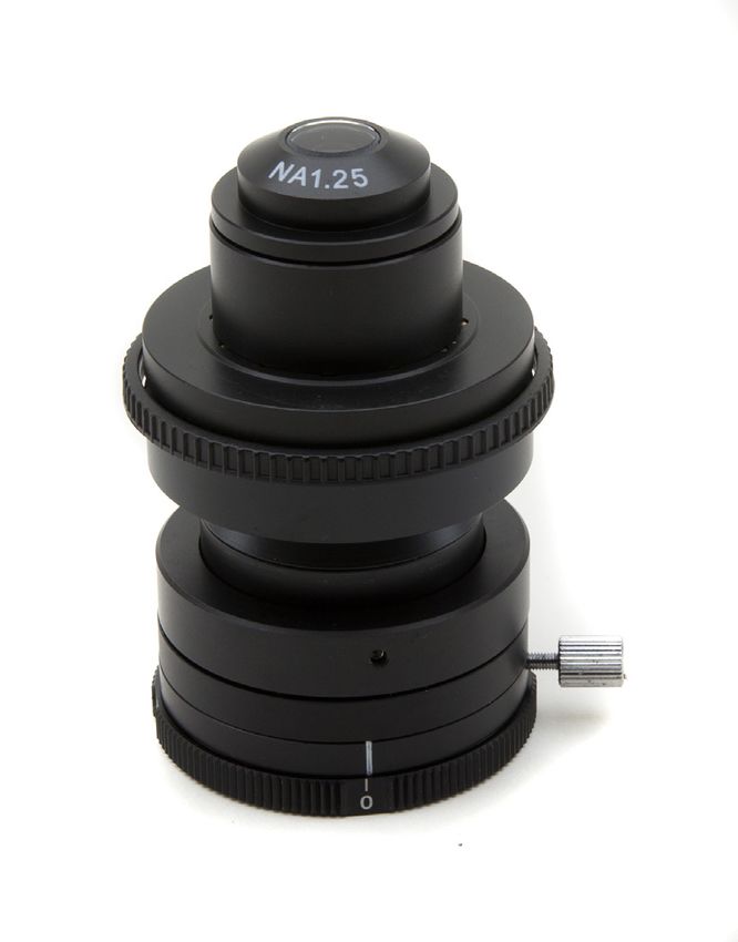
Numerical aperture setting
The value of the numerical aperture (N.A.) of the diaphragm is an indication of the contrast of the illumination
system. Matching the value of illumination system’s N.A. with that of the objective ensures the best results in
terms of contrast and image quality.
To set the numerical aperture of the illuminator, adjust the opening of the iris diaphragm (4). In this way you con-
trol contrast and image resolution.
For samples with low contrast set the iris to about 75% of the value of the objective’s numerical aperture.

     HEIGHT ADJUSTMENT FOR
     CONDENSER (5)

System centering
In order to correctly center the whole optical system, first remove the Bertrand lens out of the path by rotating its
disc. Remove also the lower polarizer filter.

The rotating stage is factory pre-centered and so it doesn’t need any additional operation.

It’s necessary to center the objectives following this procedure:

1.   Place a specimen on the stage.
2.   Insert 10x objective.
3.   Insert the two little wrenches into the holes for nosepiece centering (7).
4.   Focus your sample while continuously rotating the stage clockwise and then counter-clockwise by a little
     angle (e.g. 30° or 45°). During these oscillations you should spot a point on the sample that doesn’t rotate
     on a circumference but only revolving about itself (fixed point). With the two objective’s centering wrenches,
     bring this point in the center of the crossline.
5.   Insert the 20x objective.
6.   Insert the two little wrenches into the holes for nosepiece centering (7), above the 20x objective.
7.   Rotate the two wrenches until the same point of the sample is brought in the center of the crossline.
8.   Repeat the operation for the other objectives.

                                                          9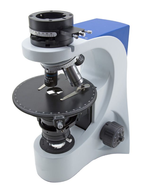
Polarized light observation
In order to correctly use the polarized light, it’s necessary to perform a setting for “light extinction”:
1. Remove from the optical path the sample, retardation plates, etc...
2. Insert the 10x objective.
3. Insert in the optical path the analyzer filter and rotate the rotation scale (8) in correspondence to
    position “0”.
4. Put the angular scale (9) of the polarizer filter to “0” position.
5. Loosen the lock screw of the polarizer and, looking into the eyepieces, rotate the scale of the polarizer until
    you obtain the complete extinction of the light (totally dark).
6. Then lock the polarizer screw.

Bertrand lens
Bertrand lens is employed in conoscopic observation mode (lens inserted) or orthoscopic mode (lens not in-
serted).

Orthoscopic observation
The path of the polarized light is parallel to the optical axis, thus allowing the observation of the optical charac-
teristics of the specimen. You can use objectives from 4x to 100x.
1. Remove the Bertrand lens out from optical path.
2. Insert the analyzer filter using the proper lever (12) and look at the sample.
3. Insert a retardation plate (11) pushing it completely inside the slot under the head.
To remove the plate from the optical path, pull it outward till the first click.

Conoscopic observation
1. Use objectives from 20X to 100X.
2. Insert the analyzer using the proper lever (12) and put it in the extinction position.
3. Insert the Bertrand lens.
4. Insert the objective of choice (from 20X to 100X).
5. Open the aperture diaphragm.
6. It’s possible to center the conoscopic image adjusting the screws (10) placed under of the head.

                                                                IMAGE CONOSCOPIC

In this manner it’s possible to look at the conoscopic images that form on the back focal plane of the objective. If
the peripheral part of the image is too dark, you can just move the condenser vertically to find the optimal posi-
tion for the illlumination.

Retardation plates
Retardation plates (1 lambda, corresponding to 530nm or Red 1° order, ¼ lambda corresponding to 137nm, and
quartz wedge) are used to make the polarization analysis more precise and refined.
Insert or remove the plate in the optical path of the microscope by pushing it into the slot (11) under the head.
Retardation plates have no visible effect when used in normal brightfield light.

                                                      10
Repair and maintenance
Microscopy environment
This microscope is recommended for use in a clean, dry and shock free environment with a temperature of
0-40°C and a maximum relative humidity of 85 % (non condensing). Use a dehumidifier if needed.
After using the microscope
The microscope should always be kept vertical when moving it so that no moving parts, such as the eye-
pieces, fall out.
Never mishandle or impose unnecessary force on the microscope. Never attempt to service the microscope
yourself. Turn down the illumination intensity control and turn the light off. Cover the microscope with the in-
cluded dust cover, and keep it in a dry and clean place.
Electrical safety precautions
Before plugging in the power supply, make sure that the supplying voltage of your region matches with the
operation voltage of the equipment and that the lamp switch is in off-position.
Users should observe all safety regulations of the region. The equipment has acquired the CE safety label.
However, users do have full responsibility to use this equipment safely.
Cleaning the optics
If the optical parts require cleaning first use compressed air.
If that is not sufficient use a soft lint-free cloth with water and a mild detergent.
And as a final option use the piece of cloth moistened with a 3:7 mixture of ethanol and ether.
Note: ethanol and ether are highly flammable liquids. Do not use them near a heat source, near sparks or
near electric equipment. Use these chemicals in a well ventilated room.
Remember to never wipe the surface of any optical items with your hands. Fingerprints can damage the op-
tics. Do not disassemble objectives or eyepieces in an attempt to clean them.
For the best results, use the VWR cleaning kit (see catalogue number below).
If you need to send the microscope to manufacturer for maintenance, please use the packaging if possible.
11Troubleshooting
Review the information in the table below to troubleshoot operating problems.
PROBLEM CAUSE SOLUTION
LIGHT DOESN’T TURN ON Power supply not connected Check that the 6Vdc power supply jack
is well inserted on the rear of the micro-
scope
Rotate the brightness adjustment control
and check if there is an increase in the
light output
IMAGE CANNOT BE SEEN The iris diaphragm aperture Completely open the iris diaphragm aper-
OR IS DARK. is not completely opened ture
Brightness level is low Rotate the brightness adjustment potenti-
ometer
Objective is not aligned with Rotate the nosepiece until an objective is
the optical axis well inserted in the optical path (it “clicks”)
IMAGE IS UNCLEAR, Objectives or filters are dirty Wipe them clean
BLURRED OR HAS INSUFFI- The iris diaphragm aperture Open the iris diaphragm aperture
CIENT CONTRAST. is not opened correctly completely
Condenser at wrong height Rotate the condenser knob until you see
a uniform illumination
User replaceable accessories and spare parts
DESCRIPTION QUANTITY CAT. NO.
Eyepiece WF20x 2 630-2000
Eyepiece WF15x 2 630-2001
Eyepiece WF20x 2 630-2002
Micrometer eyepiece WF10x/20mm 1 630-2003
Slide micrometric 26x76mm 1mm 1 630-1650
Objective E PLAN IOS 4X for serie 200&300 1 630-1639
Objective E PLAN IOS 10X for serie 200&300 1 630-1640
Objective E PLAN IOS 20X for serie 200&300 1 630-1641
Objective E PLAN IOS 40X for serie 200&300 1 630-1642
Objective E PLAN IOS 100X for serie 200&300 1 630-1643
Objective 60x/0,80 IOS E-PLAN for serie 300 1 630-2049
Darkfield condenser for dry objectives for serie 300 1 630-2060
Phototube adapter for APS-C sensor 1 630-1645
Camera adapter CCD 0,45X 1 630-1644
Battery solar pack 1 630-1637
12Technical service
Web Resources
Visit the VWR’s website at www.vwr.com for:
• Complete technical service contact information
• Access to VWR’s Online Catalogue, and information about accessories and related products
• Additional product information and special offers
Contact us For information or technical assistance contact your local VWR representative or visit. www.
vwr.com.
Warranty
VWR International warrants that this product will be free from defects in material and workmanship for a
period of five (5) years from date of delivery. If a defect is present, VWR will, at its option and cost, repair,
replace, or refund the purchase price of this product to the customer, provided it is returned during the war-
ranty period. This warranty does not apply if the product has been damaged by accident, abuse, misuse, or
misapplication, or from ordinary wear and tear. If the required maintenance and inspection services are not
performed according to the manuals and any local regulations, such warranty turns invalid, except to the ex-
tent, the defect of the product is not due to such non-performance.
Items being returned must be insured by the customer against possible damage or loss. This warranty shall
be limited to the aforementioned remedies. IT IS EXPRESSLY AGREED THAT THIS WARRANTY WILL BE
IN LIEU OF ALL WARRANTIES OF FITNESS AND IN LIEU OF THE WARRANTY OF MERCHANTABILITY.
Compliance with local laws and regulations
The customer is responsible for applying for and obtaining the necessary regulatory approvals or other au-
thorizations necessary to run or use the Product in its local environment. VWR will not be held liable for any
related omission or for not obtaining the required approval or authorization, unless any refusal is due to a
defect of the product.
13Disposal
This equipment is marked with the crossed out wheeled bin symbol to indicate that this equipment must not
be disposed of with unsorted waste.
Instead it is your responsibility to correctly dispose of your equipment the end of its life cycle by handling it
over to an authorized facility for separate collection and recycling. It is also your responsibility to decontami-
nate the equipment in case of biological, chemical and/or radiological contamination, so as to protect from
health hazards the persons involved in the disposal and recycling of the equipment.
For more information about where you can drop off your waste equipment, please contact your local dealer
from whom you originally purchased this equipment.
By doing so, you will help to conserve natural and environmental resources and you will ensure that your
equipment is recycled in a manner that protects human health.
Thank you
1415
Australia                               Hungary                                    Singapore
VWR International, Pty Ltd.             VWR International Kft.                     VWR Singapore Pte Ltd
Unit 1/31 Archimedes Place              Simon László u. 4.                         18 Gul Drive
Murarrie, Queensland 4172               4034 Debrecen                              Singapore 629468
Tel.: 1300 727 696                      Tel.: (52) 521-130                         Tel.: +65 6505 0760
Fax: 1300 135 123                       Fax: (52) 470-069                          Fax: +65 6264 3780
                                        E-mail: info@hu.vwr.com                    E-mail: sales@sg.vwr.com
Austria
VWR International GmbH                  India
Graumanngasse 7                         VWR Lab Products Private Limited           Spain
1150 Vienna                             135/12, Brigade Towers, 2nd Floor          VWR International Eurolab S.L.
Tel.: +43 1 97 002 0                    Front wing, Brigade Road,                  C/ Tecnología 5-17
Fax: +43 1 97 002 600                   Bengaluru, India – 560 025                 A-7 Llinars Park
E-mail: info@at.vwr.com                 Tel.: +91-80-41117125/26 (Bengaluru)       08450 - Llinars del Vallès
                                        Tel.: +91-2522-647911/922 (Mumbai)         Barcelona
Belgium                                 Fax: +91-80-41117120                       Tel.: 902 222 897
VWR International bvba                  E-mail: vwr_india@vwr.com                  Fax: 902 430 657
Researchpark Haasrode 2020                                                         E-mail: info@es.vwr.com
Geldenaaksebaan 464                     Ireland / Northern Ireland
3001 Leuven                             VWR International Ltd /                    Sweden
Tel.: 016 385 011                       VWR International (Northern Ireland) Ltd   VWR International AB
Fax: 016 385 385                        Orion Business Campus                      Fagerstagatan 18a
E-mail: customerservice@be.vwr.com      Northwest Business Park                    163 94 Stockholm
                                        Ballycoolin                                Tel.: 08 621 34 00
China                                   Dublin 15                                  Fax: 08 621 34 66
VWR International China Co., Ltd        Tel.: 01 88 22 222                         E-mail: kundservice@se.vwr.com
Rm.219, 2100 Dongming Road              Fax: 01 88 22 333
Pudong New District                     E-mail: sales@ie.vwr.com                   Switzerland
Shanghai 200123                                                                    VWR International GmbH
Tel.: +86-21-5898 6888                  Italy                                      Lerzenstrasse 16/18
Fax: +86-21-5855 8801                   VWR International PBI S.r.l.               8953 Dietikon
E-mail: info_china@vwr.com              Via San Giusto 85                          Tel.: 044 745 13 13
                                        20153 Milano (MI)                          Fax: 044 745 13 10
Czech Republic                          Tel.: 02-3320311/02-487791                 E-mail: info@ch.vwr.com
VWR International s. r. o.              Fax: 800 152999/02-40090010
Veetee Business Park                    E-mail: info@it.vwr.com                    Turkey
Pražská 442                                                                        Pro Lab Laboratuar Teknolojileri Ltd.Şti.
CZ - 281 67 Stříbrná Skalice            The Netherlands                            a VWR International Company
Tel.: +420 321 570 321                  VWR International B.V.                     Orta Mah. Cemal Gürsel Caddesi
Fax: +420 321 570 320                   Postbus 8198                               Ördekcioglu Işmerkezi No.32/1
E-mail: info@cz.vwr.com                 1005 AD Amsterdam                          34896 Pendik - Istanbul
                                        Tel.: 020 4808 400                         Tel.: +90216 598 2900
Denmark                                 Fax: 020 4808 480                          Fax: +90216 598 2907
VWR - Bie & Berntsen                    E-mail: info@nl.vwr.com                    Email: info@pro-lab.com.tr
Transformervej 8
2730 Herlev                             New Zealand                                UK
Tel.: 43 86 87 88                       Global Science - A VWR Company             VWR International Ltd
Fax: 43 86 87 90                        241 Bush Road                              Customer Service Centre
E-mail: info@dk.vwr.com                 Albany 0632, Auckland                      Hunter Boulevard - Magna Park
                                        Tel.: 0800 734 100                         Lutterworth
Finland                                 Fax: 0800 999 002                          Leicestershire
VWR International Oy                    E-mail: sales@globalscience.co.nz          LE17 4XN
Valimotie 9                                                                        Tel.: 0800 22 33 44
00380 Helsinki                          Norway                                     Fax: 01455 55 85 86
Tel.: 09 80 45 51                       VWR International AS                       E-mail: uksales@uk.vwr.com
Fax: 09 80 45 52 00                     Haavard Martinsens vei 30
E-mail: info@fi.vwr.com                  0978 Oslo
                                        Tel.: 02290
France                                  Fax: 815 00 940
VWR International S.A.S.                E-mail: info@no.vwr.com
Le Périgares – Bâtiment B                                                          GO TO VWR.COM FOR THE
201, rue Carnot                         Poland                                     LATEST NEWS, SPECIAL OFFERS
94126 Fontenay-sous-Bois cedex          VWR International Sp. z o.o.
Tel.: 0 825 02 30 30 (0,15 € TTC/min)   Limbowa 5                                  AND DETAILS OF YOUR LOCAL
Fax: 0 825 02 30 35 (0,15 € TTC/min)    80-175 Gdansk                              VWR DISTRIBUTOR
E-mail: info@fr.vwr.com                 Tel.: 058 32 38 200 do 204
                                        Fax. 058 32 38 205
Germany                                 E-mail: info@pl.vwr.com
VWR International GmbH
Hilpertstraße 20a                       Portugal
D - 64295 Darmstadt                     VWR International -
Freecall: 0800 702 00 07                Material de Laboratório, Lda
Fax: 0180 570 22 22*                    Edifício Neopark
Email: info@de.vwr.com                  Av. Tomás Ribeiro, 43- 3 D
*0,14 €/Min. aus d. dt. Festnetz        2790-221 Carnaxide
                                        Tel.: 21 3600 770
                                        Fax: 21 3600 798/9
                                        E-mail: info@pt.vwr.com

                                                           16
VWR
Microscope series 384
MANUEL D’UTILISATION
Modèle European Catalogue Number
TL384 POL 630-1936
Version: 1
du: 11, 03, 2015Adresse du Fabricant
Europe
VWR International bvba
Researchpark Haasrode 2020
Geldenaaksebaan 464
B-3001 Leuven
+ 32 16 385011
http://be.vwr.com
Pays d’origine: ITALIA
Contenu
Avertissement
Précautions
Contenu de l’emballage
Déballage
Usage
Symboles et conventions
Caractéristiques techniques
Description
Utilisation du microscope
Réparation et entretien
Résolution de problèmes
Accessoires et pièces de rechanges
Service technique
Garantie
Conformité à la législation et aux réglementations locales
Ramassage
18Avertissement
Le présent microscope est un appareil scientifique de précision créé pour offrir une durrée de vie de plusieurs
années avec un niveau d’entretien mininum. Les meilleurs composants optiques et mécaniques ont été utili-
sés pour sa conception ce qui fond de lui un appareil idéal pour une utilisation journalière.
Ce guide contient des informations importantes sur la sécurité et l’entretien du produit et par conséquent il
doit être accessible à tous ceux qui utilisent cet insrument.
Nous déclinons toute responsabilité quant à des utilisations de l’instrument non conformes au présent ma-
nuel.
Précautions
Précautions de sécurité sur le système électrique
Avant de connecter le câble d’alimentation au réseau électrique assurez vous que la tension d’entrée soit
compatible avec celle de l’appareil et que l’interrupteur de l’éclairage soit en position arrêt.
L’utilisateur devra consulter les normes de sécurités de son pays. L’appareil inclu une étiquette de sécurité
C.E. Dans tous les cas, l’utilisateur assume toute responsabilité relative à l’utilisation sûre de l’appareil.
Suivre les directives ci-dessous et lire ce manuel dans son intégralité pour un fonctionnement sûr de l’instru-
ment.
Contenu de l’emballage
DESCRIPTION QUANTITÉ
Statif du microscope avec tête, mise au point et platine rotative 1
Oculaires WF10x/20 2
Lentille de Bertrand 1
Objectif E-PLAN IOS POL 4x 1
Objectif E-PLAN IOS POL 10x 1
Objectif E-PLAN IOS POL 40x 1
Objectif E-PLAN IOS POL 60x 1
Condenseur avec polariseur tournant 1
Lames de retard(lambda, lambda/4, câle de quartz) 3
Clé Allen pour le centrage des objectifs 2
Alimentation 6Vdc 1
Housse de protection 1
19Déballage
Le microscope est logé dans une protection en polystyrène moulé. Retirez
la bande adhésive du bord de la protection et soulevez la moitié supérieure.
Prendre quelques précautions pour éviter que des éléments optiques (objec-
tifs et oculaires) tombent et s’endommagent. Avec les deux mains, extraire le
microscope et placez-le sur une surface stable.
1. Tout d’abord extraire tous les composants de l’emballage d’origine et
stocker la boîte dans un endroit sûr et sec.
2. Placer le corps principal du microscope sur une surface plane et solide.
Ne pas brancher le câble d’alimentation à cette étape.
3. Placer l’éclairage avec l’analyseur / lentille de Bertrand sur le corps princi-
pal et tourner la vis de blocage de la tête (1).
4. Insérer la tête optique et bloquer la vis.
5. Après avoir enlevé les bouchons de protection, insérer les deux ocu-
laires.
206. Brancher le câble d’alimentation externe à la prisearrière du microscope.
Si il n’est pas nécessaire d’installer des accessoires supplémentaires,
l’instrument est maintenant prêt à l’emploi.
Usage
Uniquement pour la recherche. Non destiné à usage thérapeutique ou diagnostique sur animaux ou êtres
humains.
Symboles et conventions
Le tableau suivant est un glossaire illustré des symboles qui sont utilisés dans ce manuel.
ATTENTION
Ce symbole indique un risque potentiel et vous avertit de procéder
avec prudence
Caractéristiques techniques
Tête Trinoculaire, inclinée à 30º, rotative sur 360º.
Oculaires WF10X/20mm avec croix.
Lentille de Bertrand Amovible; centrable.
Kit de polarisation Filtre analyseur rotatif 0°-90º Lames de retard incluse: rouge 1° ordre (λ), λ/4,
câle de quartz.
Revolver 4-positions avec tous les objectifs centrables.
Objectifs E-PLAN IOS POL (strain-free): 4x/0.10, 10x/0.25, 40x/0.65, 60x/0.80.
Mise au point Macrométrique et micrométrique coaxiale.
Platine 160mm de diam. ; rotative sur 360°, bouton d’arrêt et Vernier 0.1°.
Condenseur O.N 1.25, avec diaphragme à iris, réglable et centrable. Avec filtre rotatif polarisant.
Éclairage Système d’illumination P-LED3, avec variateur d’intensité.
Alimentation Alimentation externe: entrée 100-240Vac 50-60Hz / sortie 6Vdc 1A
Description
LENTILLE DE BERTRAND
VIS DE CENTRAGE (10)
21PORT PHOTO/VIDÉO
OCULAIRES (UN AVEC
RETICULE GRADUÉ)
ANNEAU DE
RÉGLAGE
DIOPTRIQUE
LENTILLE DE BERTRAND(13)
ÉCHELLE DE
ROTATION DE
L’ANALISEUR(8)
LEVIER D’INSER-
TION DE L’ANALY- LAME DE RETARD (11)
SEUR(12)
OUVERTURES POUR LE
CENTRAGE DU REVOLVER (7)
OBJECTIF
PLATINE ROTATIVE
VIS DE BLOCAGE DE
LA ROTATION DE LA
PLATINE
VIS DE CENTRAGE
DU CONDENSEUR
(2)
POLARISEUR
22Utilisation du microscope
Réglage de la tête d’observation
Desserrer la vis de serrage, tourner la tête jusqu’à trouver une position confortable pour l’observation et la
revisser de nouveau.
Positionnement de l’échantillon sur la platine porte-préparations
Pour bloquer la lamelle sur la platine, utiliser les petites pinces appropriées. S’assurer de bien positionner la
lamelle au centre sur l’ouverture présente sur la platine.
Réglage du système d’éclairage
Le microscope est équipé d’un éclairage à LED blanche. Tourner le bouton de réglage de la luminosité, j’usqu’à
trouver la lumière idéale pour l’observation.
Réglage de la distance interpupillaire
Régler la distance interpupillaire des porte- oculaires sur la tête
jusqu’à obtenir la vision d’un seul champ lumineux en tenant
immobiles les parties droite et gauche de la tête d’observation avec
les deux mains. Le point (°) situé sur le porte-oculaire indique la
distance interpupillaire choisie. Mémoriser cette valeur pour faciliter
les réglages successifs.
Réglage de la tension de mise au point
La tension de la mise au point macrométrique est configurée en
usine. Pour modifier la tension en fonction de ses préférences,
tourner la commande (3) en sens horaire pour augmenter la tension.
Une tension excessive pourrait endommager le mécanisme de
mise au point. Une tension trop réduite provoquerait la descente
de la platine par gravité ou
une perte de mise au point soudaine. Dans ce cas, tourner la bague
pour augmenter la tension.
COMMANDE DE MACROMÉTRIQUE MICROMÉTRIQUE
RÉGLAGE DE LA
TENSION (3)
Réglage de la compensation dioptrique
Tourner la bague de réglage dioptrique de l’oculaire à michemin à
gauche.
Tourner la commande de mise au point macrométrique pour
focaliser la lamelle en utilisant un objectif à faible grossissement
et bloquer de nouveau la vis. Régler la commande de mise au
point micrométrique jusqu’à obtenir une image claire et définie en
observant avec l’oeil droit et répéter l’opération avec l’anneau de
compensation dioptrique gauche et l’oeil gauche. Lorsque l’image
est mise au point, choisir l’objectif en tournant le revolver.
23Réglage du condenseur
Le condenseur, situé sous la platine porte-préparations, a les caractéristiques suivantes:
LEVIER DE RÉGLAGE DU
DIAPHRAGME D’ OUVERTURE
(4)
POLARISEUR ROTATIF AVEC
ÉCHELLE GRADUÉE (9)
Lever ou abaisser le condenseur en agissant sur la commande de réglage (5) pour obtenir un éclairage clair et
uniforme de l’objet.
Pour centrer le condenseur : fermer complètement le diaphragme (4). En utilisant les vis de centrage du
condenseur (2), déplacer le diaphragme au centre du champ visuel. Élargir ensuite graduellement le diaphragme
jusqu’à ce qu’il soit tangent aux bords du champ visuel. Si nécessaire, effectuer un réglage supplémentaire.
Le condenseur est centré lorsque les bords du diaphragme sont tous tangents au champ visuel.
Sur la partie inférieure du condenseur se trouve un filtre polariseur que l’on peut tourner de 360°, avec une
encoche de référence pour la mesure précise de l’angle de rotation
24Réglage de l’ouverture numérique.
La valeur de l’ouverture numérique (O.N.) du diaphragme est l’indication du contraste du système d’éclairage.
En faisant coïncider la valeur d’O.N. du système d’éclairage avec celle de l’objectif, on obtient les meilleurs
résultats en termes de contraste et de qualité de l’image.
Pour régler l’ouverture numérique de l’illuminateur, régler l’ouverture du diaphragme à iris (4). De cette façon il
est possible d’agir sur le contraste et la résolution de l’image. Pour les échantillons à faible contraste, régler le
diaphragme à environ 75% de la valeur de l’ouverture numérique de l’objectif.
COMMANDE DE RÉGLAGE DE LA
HAUTEUR DU CONDENSEUR (5).
Centrage du système
Pour centrer de façon correcte tout le système, enlever la lentille de Bertrand du parcours optique. Enlever
également le polariseur inférieur.
La platine rotative est pré-centrée en usine et ne nécessite aucune opération supplémentaire. Il faut effectuer le
centrage des objectifs en suivant la procédure suivante:
1. Placer une préparation.
2. Insérer l’objectif 10x.
3. Insérer les deux petites vis de centrage fournies dans les ouvertures de centrage du revolver (7).
4. Mettre au point l’échantillon et tourner la platine de façon continue en sens horaire et anti- horaire de quelques
degrés (par ex : 30°ou 45°). Durant ces oscillations il faut identifier dans l’échantillon un point qui ne décrive
pas une circonférence mais qui tourne uniquement sur lui-même (point fixe). En utilisant les deux petites vis
de centrage, faire en sorte que ce point se positionne au centre du réticule de l’oculaire.
5. Insérer l’objectif 20x.
6. Insérer les deux petites vis de centrage fournies dans les ouvertures de centrage du revolver (7), au dessus
de l’objectif 20x.
7. En agissant sur les petites vis de centrage, déplacer le même point jusqu’à le porter au centre de l’oculaire.
8. Répéter l’opération pour tous les autres objectifs.
25Observation en lumière polarisée
Pour opérer correctement en lumière polarisée, il faut exécuter l’opération “d’extinction de la lumière»:
1. Enlever l’échantillon, les lames de retard, etc. du parcours optique.
2. Insérer l’objectif 10X.
3. Insérer l’analyseur dans le parcours optique et positionner l’échelle de rotation (8) sur 0°.
4. Positionner l’échelle du polariseur (9) sur 0°.
5. Desserrer la vis de blocage du polariseur et en observant à l’intérieur des oculaires, tourner l’échelle du
polariseur jusqu’à obtenir l’extinction totale (sombre aux oculaires).
6. Serrer la vis.
Utilisation de la lentille de Bertrand
La lentille de Bertrand est utilisée pour effectuer les observations en conoscopie (lentille insérée) et orthoscopie
(lentille désinsérée).
Observation en orthoscopie
Le parcours de la lumière polarisée est parallèle à l’axe optique et permet l’observation des caractéristiques
optiques de la préparation. Il est possible d’utiliser les objectifs de 4X à 100X.
1. Enlever la lentille de Bertrand du parcours optique.
2. Insérer l’analyseur avec le levier approprié (12) et effectuer l’observation.
3. Introduire une lame de retard (11) dans le logement spécial en la poussant à fond pour l’insérer dans le par-
cours optique. Pour enlever la lame de retard du parcours optique, l’extraire jusqu’au premier clic..
Observation en conoscopie
1. Utiliser des objectifs de 20X à 100X.
2. Introduire l’analyseur par l’intermédiaire du levier approprié (12) en le réglant sur la position d’extinction.
3. Insérer la lentille de Bertrand.
4. Insérer un objectif à choix (de 20X à 100X).
5. Ouvrir le diaphragme d’ouverture.
6. Il est possible de centrer l’image conoscopique en agissant directement sur les vis de centrage (10) du dis-
positif.
IMAGE CONOSCOPIQUE
De cette façon, il est possible de visualiser des images conoscopiques qui se forment sur le plan focal arrière de
l’objectif. Si la périphérie de l’image conoscopique est foncée, il suffit de déplacer le condenseur verticalement
et trouver la position parfaite d’éclairage.
Utilisation des lames de retard
Les lames de retard (1 lambda qui correspond à 530 nm ou Rouge 1° ordre, ¼ lambda, qui correspond à 137
nm, câle de quartz) sont utilisées pour rendre l’observation en lumière polarisée plus sensible et raffinée.
Insérer ou extraire du microscope la lame de retard (11) (pendant l’observation en lumière polarisée). Les lames
n’ont pas d’effet lorsque l’observation est effectuée en fond clair.
26Réparation et entretien
Environnement de travail
Il est conseillé d’utiliser le microscope dans un environnement propre et sec, protégé des impactes, à une
température comprise entre 0°C y 40°C et avec une humidité relative maximale de 85% (en absence de
condensation). Il est conseillé d’utiliser un déshumidificateur si nécessaire.
Conseils avant et après l’utilisation du microscope
- Maintenir le microscope toujours en position verticale lorsque vous le déplacez. Assurez vous que les
pièces mobiles (oculaires) ne tombent pas.
- Manipulez avec attention le microscope en évitant de le forcer.
- Ne réparez pas le microscope vous même
- Éteindre immédiatement la lumière après avoir utilisé le microscope, couvrez le avec la housse prévue à cet
effet et conservez le dans un endroit propre et sec.
Précaution de sécurité sur le système électrique
Avant de connecter le câble d’alimentation sur le réseau électrique assurez vous que la tension d’entrée soit
compatible avec celle de l’appareil et que l’interrupteur de l’éclairage soit en position arrêt.
L’utilisateur devra consulter les normes de sécurités de son pays. L’appareil inclu une étiquette de sécurité
C.E. Dans tous les cas, l’utilisateur assume toute responsabilité relative à l’utilisation sûre de l’appareil.
Nettoyage des optiques
Si vous souhaitez nettoyer les optiques, utilisez dans un premier temps de l’air comprimé Si cela n’est pas
suffisant, utilisez alors un chiffon non effiloché, humidifié avec un peu d’eau et avec un détergent délicat.
Comme dernière option, il est possible d’utiliser un chiffon humide avec une solution de 3:7 d’éthanol et
d’éther. Attention: l’éthanol et l’éther sont des substances hautement inflammables.
Ne les utilisez pas près d’une source de chaleur, d’étincelles ou d’appareils électriques.
Les substances chimiques doivent être utilisées dans un environnement aéré Ne pas frotter la superficie
d’aucun des composants optiques avec les mains. Les empreintes digitales peuvent endommager les parties
optiques.
Pour les meilleurs résultats, utiliser le kit de nettoyage (code ci-dessous).
Conserver l’emballage d’origine dans le cas où il serait nécessaire de retourner le microscope au
fournisseur pour un entretien ou une réparation.
27Résolution de problèmes
Reportez-vous à l’information dans le tableau ci-dessous pour résoudre les problèmes opérationnels.
PROBLÈME CAUSE SOLUTION
L’ÉCLAIRAGE NE L’alimentation n’est pas Vérifiez l’alimentation 6Vdc soit bien
S’ALLUME PAS branché inséré à l’arrière du microscope.
Potentiomètre Tourner le potentiomètre de réglage de
la luminosité et vérifier si une augmentation
de lumière se produit.
L’IMAGE NE SE VOIT PAS OU Le diaphragme n’est pas Ouvrez complètement le diaphragme.
EST SOMBRE. complètement ouvert.
Le niveau de luminosité est Tourner le potentiomètre de réglage de
faible. la luminosité.
L’objectif n’est pas aligné Girar el revolver hasta que uno de los
avec l’axe optique. objetivos esté bien posicionado en el centro
óptico (cuando hace “click” al girar el
revólver, está en su lugar correcto)
L’IMAGE EST FLOUE OU LE Les objectifs ou les filtres Les nettoyer.
CONTRASTE EST sont sales.
INSUFFISANT Le diaphragme n’est pas Ouvrez complètement le diaphragme.
complètement ouvert.
Le condenseur n’est pas à Tournez la commande du condensateur
la bonne hauteur jusqu’à vous voyez un éclairage
uniforme
Accessoires et pièces de rechanges
DESCRIPTION QUANTITÉ CAT. NO.
Oculaires WF10x/20mm 2 630-2000
Oculaires WF15x 2 630-2001
Oculaires WF20x 2 630-2002
Oclulaire micromètrique WF10x/20mm 1 630-2003
Slide micrometrique 26x76mm 1mm 1 630-1650
Objectif E PLAN IOS 4X pour serie 200&300 1 630-1639
Objectif E PLAN IOS 10X pour serie 200&300 1 630-1640
Objectif E PLAN IOS 20X pour serie 200&300 1 630-1641
Objectif E PLAN IOS 40X pour serie 200&300 1 630-1642
Objectif E PLAN IOS 100X pour serie 200&300 1 630-1643
Objectif 60x/0,80 IOS E-PLAN pour serie 300 1 630-2049
Condenseur pour fond noir pour objetifs secspour serie 300 1 630-2060
Adaptateur camera reflex APS-C sensor 1 630-1645
Adaptateur 0,5X CCD 1 630-1644
Batterie solaire 1 630-1637
28Service technique
Ressources Web
Visitez le site Web de VWR à l’adresse www.vwr.com pour:
• Coordonnées complètes du service technique.
• Accès au catalogue en ligne de VWR et à des informations sur les accessoires et produits connexes.
• Informations supplémentaires sur les produits et les offres spéciales.
Contactez-nous Pour plus d’informations ou une assistance technique, contactez votre représentant VWR
local ou visitez le site www.vwr.com.
Garantie
VWR International garantit ce produit pièces et main-d’œuvre pour une durée de cinq (5) ans à compter
de la date de livraison. En cas de vice, VWR pourra, à sa discrétion et à ses frais, réparer, remplacer ou
rembourser au client le prix d’achat du produit, à condition qu’il lui soit retourné au cours de la période de
garantie. Cette garantie n’est pas applicable si le dommage provient d’un accident, d’une utilisation abusive
ou incorrecte, d’une mauvaise application ou de l’usure normale du produit. Cette garantie deviendrait non
valide dans le cas où les services de maintenance et de vérification requis ne seraient pas exécutés confor-
mément aux manuels et réglementations locales, sauf exception si le défaut du produit n’est pas imputable
à cette non exécution.
Il est recommandé au client d’assurer les éléments retournés contre les risques éventuels d’endommagement
ou de perte. Cette garantie se limite aux réparations susmentionnées. IL EST EXPRESSÉMENT CONVENU
QUE LA PRÉSENTE GARANTIE SE SUBSTITUE À TOUTES LES GARANTIES DE CONFORMITÉ ET DE
VALEUR MARCHANDE.
Conformité à la législation et aux réglementations locales
Le client est chargé de la demande et de l’obtention des approbations réglementaires et autres autorisations
nécessaires à l’utilisation ou à l’exploitation du Produit dans l’environnement local. VWR ne saura être tenu
responsable de toute omission ou non obtention des approbations ou autorisations requises, sauf exception
si le refus est dû à un défaut du produit.
29Ramassage
Le symbole du conteneur qui figure sur l’appareil électrique ou sur son emballage indique que le produit de-
vra être, à la fin de sa vie utile, séparé du reste des résidus. Pour la gestion du ramassage sélectif du présent
instrument, l’utilisateur qui souhaite éliminer l’appareil devra se mettre en contact avec le fabricant et suivre
la procédure que celui-ci a adopté pour permettre le ramassage sélectif de l’appareil. Le ramassage sélectif
correct de l’appareil pour son recyclage, traitement et élimination compatible avec l’environnement contribue
à éviter d’éventuels effets négatifs sur l’environnement et la santé et favorise la réutilisation et/ou recyclage
des composants de l’appareil. L’élimination du produit de manière abusive de la part de l’utilisateur entraînera
l’application de sanctions administratives sur la norme en vigueur.
Merci.
3031
Allemagne                               Hongrie                                    République Tchèque
VWR International GmbH                  VWR International Kft.                     VWR International s. r. o.
Hilpertstraße 20a                       Simon László u. 4.                         Veetee Business Park
D - 64295 Darmstadt                     4034 Debrecen                              Pražská 442
Freecall: 0800 702 00 07                Tel.: (52) 521-130                         CZ - 281 67 Stříbrná Skalice
Fax: 0180 570 22 22*                    Fax: (52) 470-069                          Tel.: +420 321 570 321
Email: info@de.vwr.com                  E-mail: info@hu.vwr.com                    Fax: +420 321 570 320
*0,14 €/Min. aus d. dt. Festnetz                                                   E-mail: info@cz.vwr.com
                                        Inde
Australie                               VWR Lab Products Private Limited           Royaume-Uni
VWR International, Pty Ltd.             135/12, Brigade Towers, 2nd Floor          VWR International Ltd
1/31 Archimedes Place                   Front wing, Brigade Road,                  Customer Service Centre
Murarrie, Queensland, 4172              Bengaluru, India – 560 025                 Hunter Boulevard - Magna Park
Tel.: 1300 727 696                      Tel.: +91-80-41117125/26 (Bengaluru)       Lutterworth
Fax: 1300 135 123                       Tel.: +91-2522-647911/922 (Mumbai)         Leicestershire
                                        Fax: +91-80-41117120                       LE17 4XN
Autriche                                                                           Tel.: 0800 22 33 44
VWR International GmbH                  Irlande / Irlande du Nord                  Fax: 01455 55 85 86
Graumanngasse 7                         VWR International Ltd /                    E-mail: uksales@uk.vwr.com
1150 Wien                               VWR International (Northern Ireland) Ltd
Tel.: 01 97 002 0                       Orion Business Campus                      Singapour
Fax: 01 97 002 600                      Northwest Business Park                    VWR Singapore Pte Ltd
E-mail: info@at.vwr.com
                                        Ballycoolin                                18 Gul Drive
Belgique                                Dublin 15                                  Singapore 629468
VWR International bvba                  Tel.: 01 88 22 222                         Tel.: +65 6505 0760
Researchpark Haasrode 2020              Fax: 01 88 22 333                          Fax: +65 6264 3780
Geldenaaksebaan 464                     E-mail: sales@ie.vwr.com                   E-mail: sales@sg.vwr.com
3001 Leuven
Tel.: 016 385 011                       Italie                                     Suède
Fax: 016 385 385                        VWR International PBI S.r.l.               VWR International AB
E-mail: customerservice@be.vwr.com      Via San Giusto 85                          Fagerstagatan 18a
                                        20153 Milano (MI)                          163 94 Stockholm
Chine                                   Tel.: 02-3320311/02-487791                 Tel.: 08 621 34 00
VWR International China Co., Ltd        Fax: 800 152999/02-40090010                Fax: 08 621 34 66
Rm.219, 2100 Dongming Road              E-mail: info@it.vwr.com                    E-mail: kundservice@se.vwr.com
Pudong New District
Shanghai 200123                         Norvège                                    Suisse
Tel.: +86-21-5898 6888                  VWR International AS                       VWR International GmbH
Fax: +86-21-5855 8801                   Haavard Martinsens vei 30                  Lerzenstrasse 16/18
E-mail: info_china@vwr.com              0978 Oslo                                  8953 Dietikon
                                        Tel.: 0 2290                               Tel.: 044 745 13 13
Danemark                                Fax: 815 00 940                            Fax: 044 745 13 10
VWR - Bie & Berntsen                    E-mail: info@no.vwr.com                    E-mail: info@ch.vwr.com
Transformervej 8
2730 Herlev                             Nouvelle-Zélande                           Turquie
Tel.: 43 86 87 88                       Global Science - A VWR Company             Pro Lab Laboratuar Teknolojileri Ltd.Şti.
Fax: 43 86 87 90                        241 Bush Road                              a VWR International Company
E-mail: info@dk.vwr.com                 Albany 0632, Auckland                      Orta Mah. Cemal Gürsel Caddesi
                                        Tel.: 0800 734 100                         Ördekcioglu Işmerkezi No.32/1
Espagne                                 Fax: 0800 999 002                          34896 Pendik - Istanbul
VWR International Eurolab S.L.          E-mail: sales@globalscience.co.nz          Tel.: +90216 598 2900
C/ Tecnología 5-17                                                                 Fax: +90216 598 2907
A-7 Llinars Park                        Pays-Bas                                   Email: info@pro-lab.com.tr
08450 - Llinars del Vallès              VWR International B.V.
Barcelona                               Postbus 8198
Tel.: 902 222 897                       1005 AD Amsterdam
Fax: 902 430 657                        Tel.: 020 4808 400
E-mail: info@es.vwr.com                 Fax: 020 4808 480
                                        E-mail: info@nl.vwr.com
Finlande
VWR International Oy                    Pologne
Valimotie 9                             VWR International Sp. z o.o.
00380 Helsinki                          Limbowa 5                                  RENDEZ-VOUS SUR WWW.
Tel.: 09 80 45 51                       80-175 Gdansk
Fax: 09 80 45 52 00                                                                VWR.COM ET RETROUVEZ
                                        Tel.: 058 32 38 200 do 204
E-mail: info@fi.vwr.com                  Fax. 058 32 38 205                         NOS NOUVEAUTÉS ET OFFRES
                                        E-mail: info@pl.vwr.com                    SPÉCIALES
France
VWR International S.A.S.
Le Périgares – Bâtiment B
                                        Portugal
                                        VWR International - Material de Labo-
201, rue Carnot
94126 Fontenay-sous-Bois cedex          ratório, Lda
Tel.: 0 825 02 30 30 (0,15 € TTC/min)   Edifício Neopark
Fax: 0 825 02 30 35 (0,15 € TTC/min)    Av. Tomás Ribeiro, 43- 3 D
E-mail: info@fr.vwr.com                 2790-221 Carnaxide
                                        Tel.: 21 3600 770
                                        Fax: 21 3600 798/9
                                        E-mail: info@pt.vwr.com

                                                           32
VWR
Mikroskop 384 Serie
BEDIENUNGSANLEITUNG
Model European Catalogue Number
TL384 POL 630-1936
Version: 1
Datum: 11, 03, 2015Herstellersadresse
Europe
VWR International bvba
Researchpark Haasrode 2020
Geldenaaksebaan 464
B-3001 Leuven
+ 32 16 385011
http://be.vwr.com
Ursprungsland: ITALY
Inhalt
Warnung
Sicherheitshinweise
Lieferumfang
Auspacken
Entfernen der Verpackung
Verwendungsempfehlungen
Zeichen
Technische Angaben
Übersicht
Bedienung des Mikroskops
Wartung
Störungssuche
Zubehörteilen
Technischer Kundendienst
Gewährleistung
Befolgung lokaler Gesetze und anderer Rechtsvorschriften
Wiederverwertung
34Warnung
Dieses Mikroskop ist ein wissenschaftliches Präzisionsgerät, es wurde entwickelt für eine jahrelange Verwen-
dung bei einer minimalen Wartung. Dieses Gerät wurde nach den höchsten optischen und mechanischen
Standards und zum täglichen Gebrauch hergestellt.
Diese Bedienungsanleitung enthält wichtige Informationen zur korrekten und sicheren Benutzung
des Geräts. Diese Anleitung soll allen Benutzern zur Verfügung stehen.
Wir lehnen jede Verantwortung für eine fehlerhafte, in dieser Bedienungsanleitung nicht gezeigten Verwen-
dung Ihrer Produkte ab.
Sicherheitshinweise
Elektrische Vorsichtsmaßnahmen
Bevor Sie das Netzkabel anstecken, vergewissern Sie sich, dass die Spannung für das Mikroskop geeignet
ist und dass der Beleuchtungsschalter sich in Position OFF befindet.
Beachten Sie alle Sicherheitsvorschriften des Arbeitsplatzes, an dem Sie mit dem Mikroskop arbeiten. Das
Gerät entspricht den CE-Normen. Die Benutzer tragen während der Nutzung des Geräts die volle Verantwor-
tung dafür.
Lieferumfang
BESCHREIBUNG MENGE
Mikroskop Stativ mit Revolver, Objekttisch, Kondensor 1
Optischer Kopf 1
Objektiv 4x 1
Objektiv 10x 1
Objektiv 40x 1
Objektiv 60x 1
Okular WF10x/20mm 2
Kondensor mit drehbarem Polarisator 1
Verzögerungsplatten (Lambda, Lambda 1/4, Quarzkeil) 3
Hexagonalschlüssel für Zentrierungsobjektive 2
Netzteil 6Vdc 1
Staubabdeckung 1
Auspacken
Das Mikroskop befindet sich in einer Polystyrolverpackung. Nehmen Sie das Klebeband von der Verpackung
ab und heben Sie dann den oberen Teil der Verpackung. Bitte beachten Sie dabei, dass die optischen Kom-
ponenten (Objektive, Okulare) nicht beschädigt werden oder fallen. Halten Sie das Mikroskop mit beiden
Händen (eine rund um das Stativ und eine um den Fuß), ziehen Sie es aus der Verpackung raus und stellen
sie es auf eine flache, stabile Oberfläche.
Befestigen Sie den Kopf auf dem Stativ mit Hilfe der Spannschraube. Setzen Sie die Okulare in den Tuben
ein.
Verbinden Sie das Netzteil zur Steckdose auf der Rückseite des Mikroskops.
35Entfernen der Verpackung
Das Mikroskop ist von einer geformten Styroporverpackung umgeben. Das Kle-
beband an den Ecken der Verpackung entfernen und die obere Hälfte der Verpa-
ckung anheben. Dabei vorsichtig vorgehen und darauf achten, dass die Optikteile
(Objektive und Okulare) nicht herausfallen und beschädigt werden. Mit beiden Hän-
den (eine greift das Stativ, die andere den Fuß) das Mikroskop aus der Verpackung
ziehen und auf einen stabilen Tisch stellen.
1. Als erstes alle Einzelteile aus der Originalverpackung nehmen und diese an
einem sicheren und trockenen Ort aufbewahren.
2. Den Mikroskopkörper auf eine flache und stabile Fläche stellen.
In dieser Phase das Stromkabel noch nicht anschließen.
3. Die Halterung mit dem Analysator / Bertrandlinse am Mikroskopkörper anbrin-
gen und die Feststellschraube des Kopfes drehen.
4. Den Mikroskopkopf einsetzen und die Schraube anziehen.
5. Nachdem die Schutzkappen entfernt wurden, beide Okulare vollständig
einsetzen.
366. Das Stromkabel mit dem Anschluss an der Rückseite des Mikroskops
verbinden.
Wenn keine weiteren Zubehörteile montiert werden sollen, ist das Gerät
nun einsatzbereit.
Verwendungsempfehlungen
Nur für Forschung. Nicht für therapeutische Verwendung.
Zeichen
Die folgende Tabelle zeigt die Symbole, die in dieser Anleitung verwendet werden.
ACHTUNG
Dieses Symbol zeigt eine potentielle Gefahr und warnt, mit Vorsicht
zu verfahren.
Technische Angaben
Kopf Trinokular, 30° Schrägeinblick, um 360° drehbar.
Okulare WF 10x/20 mm mit Fadenkreuz.
Bertrandlinse Einschwenkbar, zentrierbar..
Polarisator
Halterung 0°-90° drehbarer Analysator Im Lieferumfang enthaltene Farbfilter: 1.
Ordnung rot (λ), λ/4, Quarzkeil.
Objektivrevolver 4 Positionen mit Zentriermechanismus für alle Objektive.
Objektive E-PLAN IOS POL (spannungsfrei) 4x/0.10, 10x/0.25, 40x/0.65, 60x/0.80.
Fokussiersystem Koaxialer Grob- und Feintrieb.
Kreuztisch 160 mm Durchm., um 360° drehbar mit Einstellrad und 0,1° Vernierskala.
Kondensor N.A. 1,25, mit Irisblende, mit Fokussier- und Zentrierfunktion Mit drehbarem
Polarisationsfilter.
Beleuchtung P-LED3, mit manueller Helligkeitseinstellung.
Stromzufuhr Externe Stromzufuhr: Eingang 100-240Vac 50-60Hz / Ausgang 6Vdc 1A
Übersicht
FESTSTELLSCHRAUBEN
BERTRANDLINSE (10)
37PHOTO/VIDEO PORT
OKULARE (EINES
MIT FADENKREUZ)
DIOPTRIEANPASSUNG
BERTRANSLINSEN (13)
DREHUNG
ANALYSATOR (8)
WELLENPLATTE (11)
HEBEL ZUM EINSETZEN
DES ANALYSATORS (12)
BOHRUNGEN ZUR ZENTRIERUNG
DES OBJEKTIVREVOLVERS (7)
FESTSTELLSCHRAUBE
DREHBARER KREUZ-
TISCH
FÜR KREUZTISCH
ZENTRIER-
SCHRAUBE FÜR
KONDENSOR (2)
POLARISATOR
38Bedienung des Mikroskops
Mikroskopkopf
Die Feststellschraube lockern, den Mikroskopkopf in eine angenehme Beobachtungsposition drehen und die
Feststellschraube erneut anziehen.
Den Objektträger auf den Kreuztisch legen
Den Objektträger mithilfe der Klemme auf dem Objettisch fixieren. Sicherstellen, dass die Probe über der
Kreuztischöffnung zentriert. Zum Einstellen die koaxialen Grob- und Feintriebe verwenden.
Einstellung der Beleuchtung
Das Mikroskop ist mit einer weißen LED-Leuchte ausgestattet. Den Einstellknopf für die Helligkeit auf eine für
die Beobachtung günstige Helligkeit einstellen.
Den Augenabstand einstellen
Die rechten und linken Teile des Mikroskopkopfes mit beiden
Händen festhalten und den Augenabstand durch drehen dieser
beiden Teile einstellen. Der richtige Abstand ist dann erreicht, wenn
nur ein Lichtkreis zu sehen ist.
Der weiße Punkt (°) am rechten Okular zeigt den eingestellten
Augenabstand an. Merken Sie sich diesen Wert, um spätere
Einstellungen zu erleichtern
Einstellung der Fokussierspannung
Die Spannung des Grobtriebs ist ab Werk voreingestellt.
Um die Spannung anzupassen, den Drehknopf (3) im Uhrzeigersinn
drehen, um sie zu erhöhen.
Eine überhöhte Spannung kann den Fokussiermechanismus
schädigen Eine zu geringe Spannung führt zum schwerkraftbedingten
absenken des Kreuztisches oder einem plötzlichen Verlust des
eingestellten Fokus. In diesem Fall den Drehknopf (3) drehen, um
die Spannung zu erhöhen.
DREHKNOPF ZUR GROB-TRIEB FEIN-TRIEB
SPANNUNGSEINSTELLUNG (3)
Einstellung der Dioptrien
Den Ring zum Einstellen der Dioptrien des linken Okulars in die
mittlere Position stellen. Den Grobtrieb drehen, um den beladenen
Objektträger mit einer geringen Vergrößerung scharf zu stellen.
Den feintrieb so lange drehen, bis ein klares und scharfes Bild mit
dem rechten Auge sichtbar ist. Dann den Vorgang mit dem Ring
zur Einstellung der Dioptrien am linken Okular für das linke Auge
wiederholen. Wenn das Bild scharf gestellt ist, dass erforderliche
objektiv mit dem Objektivrevolver auswählen.
39You can also read