Ambu aView Instruction for Use - Synmedic
←
→
Page content transcription
If your browser does not render page correctly, please read the page content below
Instruction for Use
Ambu® aView™

For use by trained clinicians/physicians only.
For in-hospital use.
For use with Ambu® visualization devices.
Further instruction details are available online: www.ambu.com
1                              2a                            2b

                                4

 5a   aScope 2                      5b aScope 3
                                       aScope 4 Broncho        6

                        Pat. Pending
Ambu is a registered trademark and aScope and aView are trademarks of Ambu A/S.
Contents Page
English (Instruction for Use)..........................................................................................................................4-17
Български (Указания за ползване)....................................................................................................... 18-33
Česky (Návod k použití)...............................................................................................................................34-47
Dansk (Brugsanvisning)...............................................................................................................................48-61
Deutsch (Bedienungsanleitung)...............................................................................................................62-75
Eλληvıĸά (δηγίες Xρήσεως)........................................................................................................................ 76-91
Español (Manual de instrucciones)....................................................................................................... 92-105
Eesti (Kasutusjuhised)...............................................................................................................................106-118
Suomi (Käyttöohje).................................................................................................................................... 119-132
Français (Mode d´emploi).......................................................................................................................133-146
Hrvatski (Upute za uporabu)................................................................................................................. 147-159
Magyar (Használati útmutató)..............................................................................................................160-173
Italiano (Manuale d’uso)..........................................................................................................................174-188
日本語 (使用法)................................................................................................................189-201
Lietuviškai (Naudojimo instrukcijos)..................................................................................................202-214
Latviski (Lietošanas instrukcija)............................................................................................................215-228
Nederlands (Gebruiksaanwijzing)...................................................................................................... 229-243
Norsk (Brukerveiledning)....................................................................................................................... 244-257
Polski (Instrukcja obsługi)...................................................................................................................... 258-272
Português (Manual de instruções)..................................................................................................... 273-287
Português–Brazil (Manual de instruções)........................................................................................ 288-301
Română (Instrucţiuni de utilizare).......................................................................................................302-316
Pусский (Directions for use).................................................................................................................. 317-331
Slovenčina (Návod na použitie)........................................................................................................... 332-345
Slovenšcina (Navodila za uporabo)....................................................................................................346-360
Svenska (Instruktionshandbok)............................................................................................................361-374
Türkçe (Kullanım talimatları)................................................................................................................. 375-388
( )...........................................................................................................................................389-4011. Important Information – Read Before Use
Read these safety instructions carefully before using the aView monitor. The Instruction for Use
may be updated without further notice. Copies of the current version are available upon request.
Please be aware that these instructions do not explain or discuss clinical procedures. They
describe only the basic operation and precautions related to the operation of the aView monitor.
1.1. Intended Use
The aViewTM monitor is a non-sterile, reusable digital monitor, intended to display live imaging
data from Ambu visualisation devices.
1.2. Warnings and Cautions
Failure to observe these warnings and cautions may result in patient injury or damage to the
equipment. Ambu is not responsible for any damage to the system or patient injury result-
ing from incorrect use.
WARNINGS
1. a View images must not be used as an independent diagnostic of any pathology.Physi-
cians must interpret and substantiate any finding by other means and in the light of
the patient's clinical characteristics.
2. Do not use the aView monitor if it is damaged in any way or if any part of the functional
check fails.
3. The aView is not to be used when delivering highly flammable anaesthetic gases to the
patient. This could potentially cause patient injury.
4. The aView is not to be used in a MRI environment.
5. Do not use aView during defibrillation.
6. When handling the patient do not simultaneously touch the aView power socket or
docking connector.
7. Always watch the live endoscopic image on the aView when advancing or withdrawing
a visualization device.
8. To avoid risk of electric shock, this equipment must only be connected to a supply
mains with protective earth. To disconnect aView from mains remove the mains plug
from the wall outlet.
9. Clean and disinfect the aView monitor after each use according to the instructions in
section 5. Disconnect aView from any mains power supply, remove any accessories and
make sure the aView is completely turned off before cleaning and disinfection.
10. Use of accessories, transducers and cables other than those specified or provided
by the manufacturer of this equipment could result in increased electromagnetic emis-
sions or decreased electromagnetic immunity of this equipment and result in improper
operation.
11. Electronic equipment and the aView may affect the normal function of each other. If
the aView is used adjacent to or stacked with other equipment, observe and verify nor-
mal operation of both the aView and the other electronic equipment prior to using it. It
may be necessary to adopt procedures for mitigation, such as reorientation or reloca-
tion of the equipment or shielding of the room in which it is used. Consult the tables in
appendix 1 for guidance in placing aView.
12. Be careful to check whether the image on the screen is a live image or a recorded
image and verify that the orientation of the image is as expected.
13. Portable RF communications equipment (including peripherals such as antenna cables
and external antennas) should be used no closer than 30 cm (12 inches) to any part of
the system, including cables specified by the manufacturer. Otherwise, degradation of
the performance of this equipment could result.
4EN
CAUTIONS
1. ave a suitable backup system readily available for immediate use so the procedure
H
can be continued if a malfunction should occur.
2. US federal law restricts this device for sale only by, or on the order of, a physician.
3. Keep aView dry during preparation, use and storage.
4. Pay attention to the battery symbol indicator on the aView monitor. Recharge aView
when the battery level is low (see section 4.1). It is recommended that aView is
recharged before every procedure and that a charger be readily available during use.
5. Place or hang the aView monitor on a stable support while in use. Dropping aView
could damage it.
6. Position the power cord where it is unlikely to be stepped on. Do not place any objects
on the power cord.
7. aView is not intended to be repaired. If defect aView shall be discarded.
8. The batteries in aView are not changeable and must only be removed upon disposal.
2. System Description
The aView monitor can be connected with a range of Ambu visualisation devices (cf. section 2.2
for compatible devices) to display the video image from an Ambu visualisation device. The aView
monitor is reusable. No modification of this equipment is allowed.
(e.g. for attaching
Ambu® aView™ Part numbers: Bracket the aView to an I.V. pole) Part numbers:
405002000 405017700
Model no.
JANUS2-W08-R10
(SW versions v2.XX)
For aView model no., please check backside label on aView.
aView is not available in all countries. Please contact your local sales office.
Power supplies Part numbers:
aView power supply EU/CH 405014700X
manufacturer: (not DK & UK)
x5 FSP Group Inc.
aView power supply part
UK 405013700X
DK 405012700X
number: FSP030-REAM AUS & NZ
405015700X
US 405016700X
Accessories Part numbers:
aView adaptor 405000712
cable for composite
connection
2.2. Compatible Devices
The compatible Ambu visualisation devices for aView are:
Green connection port (see “5a” on page 2) : Blue connection port (see “5b” on page 2):
- Ambu® aScope™ 2 - Ambu® aScope™ 3 Family
- Ambu® aScope™ 4 Broncho Family
Only one visualization device can be connected to aView at a time. aScope 2, aScope 3 Family and aScope 4
Broncho Family are not available in all countries. Please contact your local sales office.
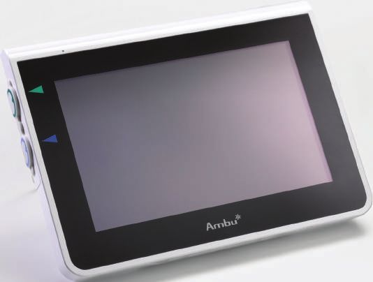
52.3. aView Parts
No. Part Function Material
1
1 Monitor Casing - PC / ABS
Rubber
2 Touch Screen Displays the image PET / Glass
4 from the Ambu
visualization device
and a touch screen
interface.
3 2 3 Stand To place the display ZDC3
on a solid surface.
4 Connection Power supply and PC / ABS
for Ambu® data connection Rubber
visualization Protected by a
6 7 devices rubber cover.
5 Power Power inlet for
charging aView. Rubber
Protected by a
rubber cover.
6 Input/output JACK connector -
connections (video-out) and
USB port.
7 Power button Push button for Rubber
5 8
power ON before
procedure and
power OFF after
procedure.
9 8 Docking For future use. -
connector
9 Power supply Powers the system PC
Power cord with PVC
country-specific plug.
10 Hexagonal key To tighten the bolt CrV
on the bracket.
10
11 Bracket Secures the monitor POM
to e.g. an IV pole.
12 Pouch hook Slide the hook PAA
through the 3 holes
on the bracket. It can
now be used to hold
12 visualization device
11 pouches with a hole
in top corner for easy
storage before and
during use.
13 13 Adapter cable For the composite PE/PVC
video-out interface
(see no. 6).
Abbreviations: PC (Polycarbonate), PE (Polyethylene), ABS (Acrylonitrile Butadiene Styrene),
ZDC3 (Zinc alloy), PVC (Polyvinylchloride), POM (Polyoxymethylene), PAA (Polyarylamide),
CrV (Chrome Vanadium)
6EN
3. Explanation of Symbols Used
Symbols for Indication Symbols for Indication
the aView the aView
Consult Instruction Date of Manufacture,
for Use. followed by YYYY-MM-DD.
Caution. Manufacturer.
Humidity limitation:
CE mark. The product
relative humidity
complies with the EU Coun-
% between 30 and
cil directive concerning
85% in operating
Medical Devices 93/42/EEC
environment.
Waste Bin symbol,
Atmospheric
indicating that waste
pressure limitation:
must be collected according
between 80 and 109
to local regulation and
kPa in operating
collection schemes for
environment
disposal of batteries.
Waste Bin symbol,
indicating that waste must
be collected according to
Connection to
local regulation and
external monitor.
collection schemes for
disposal of electronic and
electrical waste (WEEE).
Battery type Lithium ion.
Direct current. Li-ion Only applicable for the
battery inside the aView.
Re-chargeable battery.
Alternating current. Only applicable for the
battery inside the aView.
Protection against
IP30 Only for indoor use.
solid objects.
Lot Number,
Batch Code.
Tested to comply with
FCC Standards - Medical
Equipment.
Reference Number.
7Medical — general medical equipment as to
electrical shock, fire and mechanical hazards
only in accordance with
ANSI/AAMI ES60601-1:2005/(R):2012
CAN/CSA-C22.2 No. 60601-1:08 (R2013)
IEC 60601-2-18:2009. UL60601-1, 1st ed.: 2006
CAN/CSA-C22.2 No. 601.1-M90, 2005
IEC 60601-2-18:1996. Control no 4UD1.
4. Use of aView
Numbers in gray circles below refer to illustrations on page 2.
4.1. Preparation and Inspection of aView
1. losely examine aView and all parts for any damage (free from wear and tear) 1 .
C
2. Place aView on a solid flat surface by using the stand on the back of aView 2a .
If needed, aView can be placed on a pole by using the supplied bracket 2b .
3. Switch aView on by pressing the power button 3 . A white hourglass indicating that
aView is loading the User Interface will appear on the screen.
4. Check the battery indicator on aView. A full charge lasts approximately 3 hours. Charge
the aView monitor if necessary by connecting the aView power supply to the wall socket
and insert the power plug into the power inlet of aView 4 . Make sure the power supply
is present and working at any time. It is recommended to locate the nearest wall socket
before start of the procedure.
The battery icon remains white until one block is left, after which it turns red.
When remaining battery capacity is 10% the red battery icon starts flashing.
Max. battery Min. battery Fully charged
status of status of battery still connected
the aView the aView to charger
Charging is shown with blocks flashing. Current capacity is shown with non-flashing blocks.
Battery is Battery current
Battery damaged
charging capacity
The power button will light up green when aView is turned ON and not connected to mains
and orange when aView is connected to mains. When aView is turned off, fully charged and
connected to mains the button will turn green.
If the battery is critically low, the recording functions will become unavailable.
If the aView is turned off and the battery is critically low, the power button will flash orange
five times every ten seconds to remind that charging is needed.
5. Connect the selected Ambu visualization device to aView by plugging the cable connector
into the corresponding female connector on aView (push aside the rubber cover)
5a or 5b . Align the arrows on the visualisation device and aView before insertion.
6. Verify that a live video image appears on the screen. Point the distal end of the Ambu
visualization device towards an object, e.g. the palm of your hand 6 .
7. Adjust the image preferences on aView if necessary – refer to the online aView User
Guide on www.ambu.com.
4.2. Installing, Preparing and Operating the Ambu Visualization Device
Please refer to the Instruction for Use for the specific visualization device.
8EN
4.3. Operating the aView Monitor
Startup Image Mode User Interface
Starts immediately after the power A live image is available and the User
button is pressed and continues Interface displays advanced user functions
until the User Interface is loaded (refer to the online aView User Guide on
(after approximately 1 min). www.ambu.com).
A live image from the plugged in Ambu aView starts up in the Blue tab for Live Image
visualization device is available while aView Viewing and recording live image.
is loading. If no device is connected the
screen will be blue.
The screen layout may vary depending on The screen layout may vary depending on
the software version. the software version.
Interface nomenclature
Power button Video recording
Viewing and recording
Brightness adjustment
live image.
Contrast adjustment Managing saved files.
System settings and User
Snap shot
Accounts.
Live image vs. recorded image
Round BLUE buttons are shown in the blue Live Image tab and indicates a live image.
Square YELLOW or GREEN buttons are shown in the yellow File Management tab and the
green Settings tab and indicates a recorded image.
Battery status: During start up, aView powers up and configures the visualization device.
If the aView battery icon on the screen changes from fully charged to low battery (red battery)
within 30 minutes, aView must be replaced.
Connection to external monitor
The image from an Ambu visualization device can be viewed on an external monitor using the
video out interface on aView. Connect the external monitor to the composite interface on the
right side of aView using the adaptor cable supplied (refer to the online aView User Guide on
www.ambu.com). Please consult the manual of the external monitor for further information on
how to connect an external video source by composite.
94.4. After Use
Final steps
1. isconnect the Ambu visualization device from aView. For disposal of the visualisation
D
device, refer to the Instruction for Use of the specific device.
2. Switch off aView by pressing the power button for at least 2 seconds. A blue
hourglass indicating that aView is powering down will appear on the screen and
aView will power down.
3. Clean and disinfect aView (cf. section 5).
4. If the battery level of aView is low, charge the aView (cf. section 4.1).
5. Cleaning and Disinfection of aView
The aView should be cleaned and disinfected before and after each use. It is recommended that
aView is cleaned and disinfected before and after use following the instructions below. Ambu
has validated these instructions in accordance with AAMI TIR 12 & 30. Any deviation from the
instructions should be properly evaluated for effectiveness and potential adverse consequences
by the reprocessor, to ensure that the device continues to fulfil its intended purpose.
Clean and disinfect the aView according to good medical practice using one of the procedures below:
Procedure 1 - SANI-CLOTH® BLEACH from PDI
Cleaning
Use a wipe to remove heavy soil. All blood and other body fluids must be thoroughly
cleaned from surfaces and objects before disinfection by germicidal wipe.
Disinfecting
1. For heavily soiled surfaces, use a wipe to pre-clean aView prior to disinfecting.
2. Unfold a clean wipe and thoroughly wet the surface of aView.
3. The treated surfaces must remain visibly wet for a full four (4) minutes. Use additional
wipes if needed to assure continuous 4 minutes wet contact time.
4. Let aView air dry.
Procedure 2 - SUPER SANI-CLOTH® from PDI
Cleaning
Use a wipe to remove heavy soil. All blood and other body fluids must be thoroughly
cleaned from surfaces and objects before disinfection by germicidal wipe.
Disinfecting
1. For heavily soiled surfaces, use a wipe to pre-clean aView prior to disinfecting.
2. Unfold a clean wipe and thoroughly wet the surface of aView.
3. The treated surfaces must remain visibly wet for a full two (2) minutes. Use additional
wipes if needed to assure continuous 2 minutes wet contact time.
4. Let aView air dry.
Procedure 3
Cleaning
1. Prepare a cleaning solution using a standard enzymatic detergent prepared per
manufacturers recommendations. Recommended detergent: enzymatic, mild pH:
7-9, low foaming (Enzol or equivalent).
2. Soak a sterile gauze in the enzymatic solution and make sure that the gauze is moist
and not dripping.
3. Thoroughly clean the button, rubber covers, screen, external casing of the monitor
and stand with the moist gauze. Avoid getting the device wet to prevent damaging
internal electronic components.
4. Using a sterile soft bristled brush that has been dipped in the enzymatic solution,
brush the button until all evidence of soil is removed.
5. Wait for 10 minutes (or the time recommended by the manufacturer of the deter-
gent) to allow the enzymes to activate.
6. Wipe the aView clean using sterile gauze that has been moistened with RO/DI water.
Ensure all traces of the detergent are removed.
7. Repeat steps 1 to 6.
10EN
Disinfecting
Wipe the surfaces of aView for approximately 15 minutes using a piece of sterile gauze
moistened with the alcohol mixture indicated below (approximately once every 2 min-
utes). Follow safety procedures for the handling of isopropyl. The gauze should be moist
and not dripping since liquid can affect the electronics inside the aView. Pay close atten-
tion to the button, rubber covers, screen, external casing and stand, slots and gaps on the
aView. Use a sterile cotton swab for these areas.
Solution: Isopropyl (alcohol) 95%; Concentration: 70-80%; Preparation: 80cc of 95% Isopro-
pyl (alcohol) added to 20cc of purified water (PURW) (Alternatively, use EPA-registered hos-
pital disinfection wipes containing at least 70% isopropyl. Safety precautions and direc-
tions of use of the manufacturer must be followed).
After cleaning and disinfection, the aView must be submitted to the pre-check procedure in section 4.1.
Between procedures, aView must be stored in accordance with local guidelines.
6. Maintenance and Disposal
6.1. Maintenance of Battery
To prolong battery life it is recommended to fully charge the monitor at least every third
month and store it in a cool place. If the battery is flat the procedure can take up to 5 hours.
The battery should be charged at temperatures between 10 - 40°C.
6.2. Disposal
At the end of product life open up the aView and dispose of the batteries and aView separately
in accordance with local guidelines.
7. Technical Product Specifications
7.1. Standards Applied
The aView function conforms with:
– Council Directive 93/42/EEC concerning Medical Devices.
– IEC 60601-1 ed 2 Medical electrical equipment – Part 1: General requirements for safety.
– IEC 60601-1 ed 3.1 Medical electrical equipment - Part 1: General requirements for basic safe-
ty and essential performance.
– IEC 60601-1-2: Medical electrical equipment – Part 1-2 General requirements for safety –
Collateral standard: Electromagnetic compatibility - Requirements for test.
The Ambu aView power supply conforms with:
– Council Directive 93/42/EEC concerning Medical Devices.
– IEC 60601-1 ed 2 Medical electrical equipment – Part 1: General requirements for safety.
– IEC 60601-1 ed 3.1 Medical electrical equipment - Part 1: General requirements for basic safe-
ty and essential performance.
7.2. aView Specifications
Display
Max. resolution 800 * 480
Orientation Landscape
Display type 8.5” colour TFT LCD
Brightness control Yes, (“+” / ”-“)
Contrast control Yes, (“+” / ”-“)
Start up time Immediately after pressing the power button.
11Connections
USB connection Type A
Analog composite video out RCA connection (use adapter cable included)
Storage and transportation
Temperature 10 ~ 40°C (50 ~ 104°F)
Relative humidity 30 ~ 85%
Atmospheric pressure 80-109 kPa
Memory
Storage capacity 8GB
Mounting interface
Mounting interface standard VESA MIS-D, 75 C, VESA FDMI compliant display, Part
D, with centre located mounting interface
Electrical power
Power requirement 18V 1.67A DC input
Battery type 10.8V 4300mAh
Typical battery runtime of a new, fully charged battery
Battery Operation
(aView turned on and scope connected) is min. 3 hours
Protection against electrical shock Internally Powered
Fixture
Mounting interface 75 mm (2.96”)
Fits poles with thicknesses 10 mm ~ 45 mm (0.4 ~ 1.8”)
Operating environment
Temperature 10 ~ 40°C (50 ~ 104°F)
Relative humidity 30 ~ 85%
IP Protection Classification Sys- The aView is classified IP30.
tem
Atmospheric pressure 80-109 kPa
Altitude ≤ 2000 m
Dimensions
Width 241 mm (9.49")
Height 175 mm (6.89")
Thickness 33.5 mm (1.32")
Weight 1500 g (331lbs)
12EN
7.3. aView Power Supply
Dimensions
Weight 360g (0.79 lbs)
Electrical power
Power requirement 100 - 240V AC; 50-60Hz; 0.6A
Power out 18V DC; 1.67A
Protection against Class I
electrical shock
Operating environment
Temperature 10 ~ 40° C (50 ~ 104° F)
Storage
Temperature 10 ~ 40°C (50 ~ 104°F)
Relative humidity 10 ~ 90%
Plugs
Between the power supply Ø5.5mm DC jack connector
and aView
6 interchangeable types 1. Model NEMA 5 AC grounded power plug
2. Australian configuration: AS3112, AC grounded
power plug
3. UK configuration: BS1363, AC grounded power plug
4. European configuration: CEE 7, AC grounded
power plug
5. Danish configuration: 2-5a, AC grounded power plug
6. Swiss configuration: Type J, AC grounded power plug
Contact Ambu for further information.
138. Trouble Shooting
If problems occur with the aView monitor, please use this trouble-shooting guide to identify
the cause and correct the error.
Problem Possible cause Recommended action
No live image An Ambu visualization Connect an Ambu visualization device to
on the screen device is not connected the blue or green port on aView.
but User to aView.
Interface is
present on the aView and the Ambu Restart aView by pressing the power but-
display or the visualization device ton for at least 2 seconds. When aView is
image shown have communication off restart by pressing the power button
is frozen. problems. once more.
The Ambu visualization Replace the Ambu visualization device with
device is damaged. a new one.
A recorded image is Return to live image by pressing the blue
shown in the yellow Live image tab or restart aView by pressing
file management tab. the power button for at least 2 seconds.
When aView is off restart by pressing
power button once more.
Low picture Light reflecting on the Move aView to a position where no direct
quality. aView screen. light influences the screen.
Dirty / damp screen. Wipe the screen with a clean cloth.
Brightness and contrast Adjust the contrast and brightness using
settings not optimal. the designated menu on aView.
Video out is No live image on the Make sure the external monitor is connect-
not working. external screen. ed to aView using the composite cable and
that the external monitor is displaying the
correct input. The external monitor shall be
capable of receiving NTSC or PAL. Toggle
between NTSC and PAL in the video out
menu on aView for best result. The external
monitor is only displaying a live image
when aView is displaying a live image. The
image size on the external monitor is
determined by the settings in the external
monitor.
The colours, brightness Adjust the colours, brightness and contrast
and contrast looks dif- on the external monitor to achieve the
ferent from the aView desired result.
screen.
Horizontal lines (noise) If horizontal lines (noise) appear on the
on external monitor. external monitor, try to connect the aView
power supply.
Appendix 1. Electromagnetic Compatibility
Like other electrical medical equipment the system requires special precautions to ensure
electromagnetic compatibility with other electrical medical devices. To ensure electromagnetic
compatibility (EMC) the system must be installed and operated according to the EMC
information provided in this manual.
The system has been designed and tested to comply with IEC 60601-1-2 requirements for EMC
with other devices.
14EN
Guidance and manufacturer’s declaration – electromagnetic immunity
The system is intended for use in the electromagnetic environment specified below.
The customer or the user of the system should assure that it is used in such an environment.
Emissions Test Compliance Electromagnetic Environment Guidance
RF emission CISPR 11 Group 1 The system use RF energy only for
its internal function. Therefore, its RF
emissions are very low and are not
likely to cause any interference in
nearby electronic equipment.
RF emission CISPR 11 Class B The system is suitable for use in all
establishments, including domestic
Harmonic emission Not applicable establishments and those directly
IEC/EN 61000-3-2 connected to the public low-voltage
power supply network that supplies
Voltage fluctuations Complies buildings used for domestic purposes.
/ flicker emissions
IEC/EN 61000-3-3
Guidance and manufacturer’s declaration – electromagnetic immunity
The system is intended for use in the electromagnetic environment specified below.
The customer or the user of the system should assure that it is used in such an environment.
Immunity Test IEC 60601-1 Compliance Electromagnetic Envi-
test level Level ronment Guidance
Electrostatic +/- 8 kV contact +/- 8 kV contact If floors are covered with
discharge (ESD) +/- 2, 4, 8, 15 kV air +/- 2, 4, 8, 15 kV synthetic material the
IEC 61000-4-2 air relative humidity shall
be least 30 %.
Electrical fast +/- 2 kV for power +/- 2 kV power Mains power quality
transient / burst supply lines supply lines N/A shall be that of a typical
IEC 61000-4-4 +/- 1 kV for input / commercial or hospital
output lines environment.
Surge IEC 61000-4-5 +/- 1 kV line(s) Mains power quality
to line(s) shall be that of a typical
+/- 2 kV line(s) commercial or hospital
to earth environment.
Voltage Dips, shortPower frequency 30 A/m 30 A/m Power frequency
(50/60 Hz) magnetic fields
magnetic field should be at levels
IEC 61000-4-8 characteristic of a
typical location in a
typical commercial or
hospital environment.
Guidance and manufacturer’s declaration – electromagnetic immunity
The system is intended for use in the electromagnetic environment specified below.
The customer or the user of the system should assure that it is used in such an environment.
Immunity test IEC 60601 Compliance Electromagnetic
test level level Environment Guidance
Conducted 3 V RMS 3 V RMS Portable and mobile RF
Radio 0,15 MHz – 0,15 MHz – communications equipment should
Frequency 80 MHz 80 MHz be used no closer to any part of the
IEC 61000-4-6 6 V RMS 6 V RMS system, including its cables, than
in ISM bands in ISM bands the recommended separation
80 % AM at 80 % AM at distance calculated from the
1 kHz 1 kHz equation applicable to the
frequency of the transmitter.
Radiated 3 V/m 80 MHz 3 V/m
Radio to 2.7 GHz 80-2700 MHz Recommended separation distance
Frequency 80 % AM at 80% AM at d = 1.17√P
IEC 61000-4-3 1 kHz 1 kHz d = 1.17√P 80 MHz to 800 MHz
d = 2.33√P 800 MHz to 2.7 GHz
Where P is the maximum output
power rating of the transmitter
in watts (W) according to the
transmitter manufacturer and d
is the recommended separation
distance in metres (m).
Field strengths from fixed RF
transmitters, as determined by
an electromagnetic site survey,
a) should be less than the compliance
level in each frequency range
b). Interference may occur in the
vicinity of equipment marked with
the following symbol.
NOTE 1: At 80 MHz, the higher frequency range applies.
NOTE 2: These guidelines may not apply in all situations. Electromagnetic propagation is
affected by absorption and reflection from structures, objects and people.
16EN
a) Field strengths from fixed transmitters, such as base stations for radio (celluar/cordless)
telephones and land mobile radios, amateur radio, AM and FM radio broadcast, and TV
broadcast, cannot be predicted theoretically with accuracy. To assess the electromagnetic
environment due to fixed RF transmitters, an electromagnetic site survey shall be considered.
If the measured field strength in the location in which the system is used exceeds the
applicable RF compliance level above, the system shall be observed to verify normal operation.
If abnormal performance is observed, additional measures may be necessary, such as
reorienting or relocating the system.
b) Over the frequency range 150kHz to 80MHz, field strengths shall be less than 3 V/m.
Recommended Separation Distances Between Portable and Mobile RF Communication
Equipment and system.
The system is intended for use in an electromagnetic environment in which radiated RF
disturbances are controlled. The user of the system can help prevent electromagnetic
interference by maintaining a minimum distance between portable and mobile RF
communications equipment (transmitters and the system as recommended below,
according to the maximum output power of the communication equipment.
Separation distance (m) according to frequency of transmitter
Rated maximum
output power (W)
150kHZ to 80MHz 80MHz to 800MHZ 800MHz to 2.7GHz
of transmitter
D = 1.17√P D = 1.17√P D = 2.33√P
0.01 0.12 m 0.12 m 0.23 m
0.1 0.37 m 0.37 m 0.74 m
1 1.17 m 1.17 m 2.33 m
10 3.70 m 3.70 m 7.37 m
100 11.7 m 11.7 m 23.3 m
For transmitters rated at a maximum output power not listed above, the recommended
separation distance (D) in meters (m) can be estimated using the equation applicable to the
frequency of the transmitter, where P is the maximum output power rating of the transmitter
in watts (W) according to the transmitter manufacturer.
NOTE 1: At 80 MHz and 800 MHz, the separation distance for the higher frequency range applies
NOTE 2: These guidelines may not apply in all situations. Electromagnetic propagation is
affected by absorption and reflection from structures, objects and people.
Appendix 2. Warranty and Replacement Program
The warranty period for the aView is one year from delivery to the customer. Ambu agrees
to replace an aView free of charge if proof can be provided of faulty materials or faulty
workmanship. In doing so Ambu cannot accept the cost of transportation or risk of shipment.
Repair of an aView due to faulty materials or faulty workmanship may be offered in situations
where this option is available. Ambu holds the right to make the choice between repair or
replacement in every situation.
Ambu holds the right to ask the technical department at the customer site, or a similar
department, to carry out repair of an aView under proper guidance by Ambu.
A defective aView must be handled exclusively by persons authorised by Ambu A/S. To
prevent infection, it is strictly forbidden to ship contaminated medical devices. The medical
device (aView or Ambu visualization device) must be decontaminated on site before shipment
to Ambu. The cleaning and disinfection procedures explained in section 5 shall be followed.
Ambu reserve the right to return contaminated medical devices to the sender.
171. Wichtige Informationen – Vor Verwendung lesen
Lesen Sie die Sicherheitsanweisungen sorgfältig durch, bevor Sie den aView-Monitor in Betrieb
nehmen. Die Bedienungsanleitung kann ohne besondere Benachrichtigung aktualisiert und
ergänzt werden. Die aktuelle Version ist auf Anfrage erhältlich. In den hier gegebenen Anlei-
tungen werden keine klinischen Verfahren erläutert oder behandelt. Sie beschreiben aus-
schließlich die grundlegenden Schritte und Vorsichtsmaßnahmen zur Bedienung des
aView-Monitors.
1.1. Zweckbestimmung
Der aView™-Monitor ist ein nicht steriler, wiederverwendbarer digitaler Monitor zur Anzeige
von Live-Bilddaten von Ambu-Visualisierungsgeräten.
1.2. Warnhinweise und Vorsichtsmaßnahmen
Ein Nichtbeachten dieser Warnhinweise und Vorsichtsmaßnahmen kann zu Verletzungen
des Patienten oder Beschädigungen der Geräte führen. Ambu lehnt jegliche Haftung für
Schäden am System oder Verletzungen des Patienten ab, die auf eine nicht sachgemäße
Benutzung zurückzuführen sind.
WARNHINWEISE
1. a View-Bilder dürfen nicht ausschließlich zur Diagnose von Erkrankungen herangezo-
gen werden. Ärzte müssen alle Ergebnisse im Zusammenhang mit anderen Verfahren
und den klinischen Kennzeichnen des Patienten interpretieren und belegen.
2. Den aView-Monitor nicht verwenden, wenn er beschädigt ist oder ein Teil der
Funktionsprüfung fehlschlägt.
3. Der aView darf nicht in Verbindung mit brennbaren Anästhesiegasen benutzt
werden. Dies kann zu potenziellen Verletzungen des Patienten führen.
4. Der aView darf nicht in einer MRT-Umgebung verwendet werden.
5. Der aView darf nicht während der Defibrillation verwendet werden.
6. Bei der Behandlung des Patienten nicht zeitgleich den aView-Stromanschluss oder
den Anschluss der Dockingstation berühren.
7. Beachten Sie beim Einführen oder Herausziehen eines Visualisierungsgeräts immer
das Live-Bild auf dem aView-Monitor.
8. Um einen Stromschlag zu vermeiden, muss das Gerät an ein Stromnetz mit Schutzlei-
ter angeschlossen sein. Um den aView Monitor vom Stromnetz zu trennen, ziehen Sie
den Netzstecker aus der Steckdose.
9. Reinigen und desinfizieren Sie den aView-Monitor nach jeder Verwendung gemäß
den Anweisungen in Abschnitt 5. Trennen Sie den aView Monitor von der Stromver-
sorgung, entfernen Sie alle Zubehörteile und stellen Sie sicher, dass der aView-Moni-
tor vollständig ausgeschaltet ist, bevor Sie ihn reinigen und desinfizieren.
10. Nur die vom Hersteller angegebenen oder mitgelieferten Zubehörteile, Wandler und
Kabel verwenden, da andernfalls stärkere elektromagnetische Emissionen entstehen
können oder sich die Immunität dieses Geräts verringern kann, was zu einer Fehl-
funktion führen könnte.
11. Elektronische Geräte und der aView können ihre jeweilige normale Funktion gegen-
seitig beeinträchtigen. Wird der aView in unmittelbarer Nähe von anderen Geräten
betrieben, muss die einwandfreie Funktion des aView und der anderen elektroni-
schen Geräte vor der Verwendung überwacht und überprüft werden. Möglicherwei-
se ist eine Neuausrichtung oder eine Verlagerung der Ausstattung oder eine Abschir-
mung des genutzten Raums erforderlich. Anweisungen zur Platzierung des aView
finden Sie in den Tabellen in Anhang 1.
12. Achten Sie darauf, ob es sich beim angezeigten Bild auf dem Monitor um ein Live-
Bild oder eine Aufzeichnung handelt und stellen Sie sicher, dass das Bild/die Auf-
zeichnung wie erwartet ausgerichtet ist.
13. Tragbare HF-Kommunikationsgeräte (einschließlich Peripheriegeräte wie Antennenka-
bel und externe Antennen) sollten in einem Abstand von mindestens 30 cm von allen
Teilen des Systems, einschließlich der vom Hersteller angegebenen Kabel, betrieben
werden. Andernfalls kann die Leistung dieses Geräts beeinträchtigt werden.
62SICHERHEITSHINWEISE
1. alten Sie bitte ein geeignetes Backup-Gerät für den sofortigen Einsatz bereit, sodass
H
das Verfahren weitergeführt werden kann, wenn eine Funktionsstörung auftritt.
2. Dieses Gerät darf nach US-Recht nur von Ärzten bestellt und an solche verkauft werden.
3. Achten Sie darauf, dass der aView während der Vorbereitung, Verwendung und Lage-
rung trocken gehalten wird.
4. Die Akkustandanzeige auf dem aView-Monitor ist zu beachten. Sobald die Akkuladung
schwach ist, den aView wiederaufladen (siehe Abschnitt 4.1). Es wird empfohlen, den aView
vor jedem Verfahren aufzuladen und das Ladegerät bei der Verwendung bereitzuhalten.
5. Den aView während der Verwendung auf eine stabile Unterlage stellen oder aufhän-
gen. Ein Herunterfallen des aView kann zu Schäden führen.
6. Das Stromkabel so verlegen, dass niemand stolpern oder darauf treten kann. Keine
Gegenstände auf das Stromkabel stellen.
7. Der aView ist nicht zur Reparatur vorgesehen. Ist der aView defekt, muss er entsorgt werden.
8. Die Akkus im aView sind nicht austauschbar und dürfen nur zur Entsorgung
herausgenommen werden.
2. Systembeschreibung
Der aView-Monitor kann an verschiedene Visualisierungsgeräte von Ambu angeschlossen wer-
DE
den (kompatible Geräte sind Abschnitt 2.2 zu entnehmen), um Videobilder eines Ambu-Visua-
lisierungsgeräts anzuzeigen. Der aView-Monitor ist wiederverwendbar. An diesem Gerät dür-
fen keine Veränderungen vorgenommen werden.
(z. B. zur Befestigung) des aView
Ambu® aView™ Teilenummern: Halterung an einem Infusionsständer) Teilenummern:
405002000 405017700
Modellnr.
JANUS2-
W08-R10 (SW
Versionen
v2.XX)
Die Modell-Nr. des aView ist auf der Rückseite des Etiketts auf dem aView zu finden.
aView ist nicht in allen Ländern erhältlich. Bitte wenden Sie sich an Ihr Vertriebsbüro vor Ort.
Stromversorgung Teilenummern:
Hersteller der EU/CH 405014700X
(außer DK & UK)
x5 aView-Stromversorgung:
FSP Group Inc. UK 405013700X
Teile-Nr. der DK 405012700X
aView-Stromversorgung: AUS & NZ 405015700X
FSP030-REAM US 405016700X
Zubehör Teilenummern:
aView-Adapter Kabel für 405000712
Composite-Anschluss
2.2. Kompatible Geräte
Die folgenden Ambu-Visualisierungsgeräte sind mit dem aView kompatibel:
Grüner Anschluss (siehe „5a“ auf Seite 2): Blauer Anschluss (siehe „5b“ auf Seite 2):
- Ambu® aScope™ 2 - Ambu® aScope™ 3 Familie
- Ambu® aScope™ 4 Broncho Familie
Es kann jeweils nur ein Visualisierungsgerät an den aView angeschlossen werden. aScope 2, aScope 3 Familie und
aScope 4 Broncho Familie sind nicht in allen Ländern erhältlich. Bitte wenden Sie sich an Ihr Vertriebsbüro vor Ort.
632.3. aView-Teile
Pos. Teil Funktion Material
4
1 1 Monitorgehäuse - PC/ABS
Gummi
2 Touchscreen Zeigt das Bild des PET/Glas
Ambu-Visualisierungsgeräts
und eine Touchscreen-Ober-
fläche an.
3 Untergestell Zum Aufstellen des Monitors ZDC3
auf einer ebenen Oberfläche.
3 2 4 Anschluss für Stromversorgung PC/ABS
Ambu®-Visualisie- und Datenverbindung Gummi
rungsgeräte Geschützt durch eine
Gummiabdeckung.
6 7
5 Stromeingang Stromanschluss zum
Laden des aView. Gummi
Geschützt durch eine
Gummiabdeckung.
6 Eingangs-/Ausgangs- Anschlussstecker (Videoaus- -
anschlüsse gang) und USB-Anschluss.
7 Ein-/Aus-Taste Vor dem Verfahren Gummi
5 8 einschalten und nach dem
Verfahren ausschalten.
9
8 Anschluss der Für künftige Anwendungen. -
Dockingstation
9 Stromversorgung Versorgt das PC
System mit Strom PVC
Stromkabel mit länderspezifi-
schem Stecker.
10 Sechskantschlüssel Zum Anziehen der Schraube CrV
10 an der Halterung.
11 aView Monitor Zur Befestigung des Moni- POM
Halterung tors, z. B. an einen Infusions-
ständer.
12 aScope Haken Führen Sie den Haken durch PAA
die 3 Löcher der Halterung. Er
kann nun verwendet werden,
um Visualisierungsgerät-Ver-
packungen mit einem Loch in
12
der oberen Ecke zu befesti-
gen, sodass diese vor und
11
während der Anwendung
griffbereit bleiben.
13 Adapterkabel Für die Composite-Videoaus- PE/PVC
gangs-Schnittstelle (siehe
Pos. 6).
13
Abkürzungen: PC (Polycarbonat), PE (Polyethylen), ABS (Acrylnitril-Butadien-Styrol),
ZDC3 (Zinklegierung), PVC (Polyvinylchlorid), POM (Polyoxymethylen), PAA (Polyarylamid),
CrV (Chrom-Vanadium)
643. Erklärung der verwendeten Symbole
Symbole für Bedeutung Symbole für Bedeutung
den aView den aView
Bedienungsanleitung Herstellungsdatum,
beachten. gefolgt von JJJJ-MM-TT.
Warnung. Hersteller.
CE-Kennzeichnung.
Feuchtigkeitsbeschränkung:
Das Produkt erfüllt die
relative Feuchtigkeit zwi-
% schen 30 und 85 % in
Richtlinie 93/42/EWG
des Rates über Medi-
Betriebsumgebung.
zinprodukte
Abfallbehälter-Symbol
zeigt an, dass Abfälle
Beschränkung des atmo-
gemäß örtlicher Vor-
sphärischen Drucks: zwi-
schriften und örtlicher
schen 80 und 109 kPa in
DE
Sammelordnung zur Ent-
Betriebsumgebung
sorgung von Akkus ent-
sorgt werden müssen.
Abfallbehälter-Symbol
zeigt an, dass Abfälle
gemäß der örtlichen
Vorschriften und der
örtlichen Sammelord-
Anschluss an
nung zur Entsorgung
externen Monitor.
von elektronischen und
elektrischen Abfällen
entsorgt werden müs-
sen (Elektro- und Elekt-
ronik-Altgeräte).
Lithium-Ionen-Akku.
Gleichstrom. Li-ion Gilt nur für den Akku
im Inneren des aView.
Akku. Gilt nur für
Wechselstrom. den Akku im Inneren
des aView.
Schutz vor Nur zur Verwendung
IP30
festen Gegenständen. in Innenräumen.
Lotnummer,
Chargencode. Entspricht der
FCC-Norm – Medizini-
sche Geräte.
Artikelnummer.
65Medizinisch – allgemeine medizinische
Geräte hinsichtlich Stromschlägen, Brand
und mechanischen Gefahren nur gemäß
ANSI/AAMI ES60601-1:2005/(R):2012
CAN/CSA-C22.2 No. 60601-1:08 (R2013)
IEC 60601-2-18:2009. UL60601-1,
1st ed.: 2006
CAN/CSA-C22.2 No. 601.1-M90, 2005
IEC 60601-2-18:1996. Kontrollnr. 4UD1.
4. Verwendung des aView
Die nachstehendenden, mit grauen Kreisen hinterlegten Nummern verweisen auf Abbildun-
gen auf Seite 2.
4.1. Vorbereitung und Prüfung des aView
1. en aView und alle Teile auf Schäden überprüfen (frei von Verschleißerscheinungen) 1 .
D
2. Den aView mit dem auf der Rückseite vorhandenen Ständer auf eine ebene Oberfläche
stellen 2a . Bei Bedarf kann der aView auch mit der beiliegenden Halterung auf einer
Stange aufgehängt werden 2b .
3. Schalten Sie den aView durch Betätigen Einschalttaste ein 3 . Eine weiße Sanduhr wird
auf dem Bildschirm angezeigt, die angibt, dass der aView die Benutzerschnittstelle lädt.
4. Überprüfen Sie die Akkuanzeige am aView. Eine volle Akkuladung sollte etwa 3 Stunden
halten. Den aView-Monitor bei Bedarf durch Anschließen des Netzsteckers an die Steck-
dose aufladen und den Netzstecker in den Stromeingang des aView stecken 4 . Stellen
Sie sicher, dass das Netzteil angeschlossen ist und jederzeit funktioniert.
Vor der Anwendung wird empfohlen die nächst gelegene Steckdose zu ermitteln.
Das Akku-Symbol ist weiß, solange noch ein Balken angezeigt wird. Danach ist das Symbol rot.
Wenn der Akku nur noch zu 10 % Kapazität hat, blinkt das rote Akkusymbol.
Vollständig geladener
Max. Akku-La- Min. Akku-La-
Akku, der noch am
dezustand dezustand des
Ladegerät ange-
des aView aView
schlossen ist
Wenn der Akku geladen wird, blinken die Balken. Der aktuelle Ladezustand wird durch
nicht-blinkende Balken angezeigt.
Aktueller Lade-
Akku wird
zustand des Akku beschädigt
geladen.
Akkus
Die Einschalttaste leuchtet grün, wenn der aView EINGESCHALTET und nicht an das Stromnetz
angeschlossen ist; wenn der aView an das Stromnetz angeschlossen ist, leuchtet die Taste
orange. Wenn der aView ausgeschaltet, vollständig aufgeladen und an das Stromnetz ange-
schlossen ist, leuchtet die Taste grün.
Wenn der Akkuladezustand sehr niedrig ist, sind die Aufnahmefunktionen nicht verfügbar.
Falls der aView ausgeschaltet und der Akkuladezustand sehr niedrig ist, blinkt die Einschalttas-
te alle zehn Sekunden fünf Mal orange auf, um daran zu erinnern, dass das Gerät aufgeladen
werden muss.
5. Schließen Sie das ausgewählte Ambu-Visualisierungsgerät am aView an, indem Sie den
Kabelstecker in die entsprechende Buchse am aView stecken (schieben Sie die Gummiab-
deckung zur Seite) 5a oder 5b . Richten Sie die Pfeile am Visualisierungsgerät und am
aView vor dem Einstecken aufeinander aus.
666. ergewissern Sie sich, dass das Live-Bild auf dem Bildschirm angezeigt wird. Zeigen
V
Sie mit dem distalen Ende des Ambu-Visualisierungsgeräts auf ein Objekt, z. B. auf Ihre
Handfläche 6 .
7. Passen Sie ggf. die Bildeinstellungen auf dem aView an (siehe Online-aView-Bedienungs-
anleitung auf www.ambu.de).
4.2. Installation, Vorbereitung und Betrieb des Ambu Visualisierungsgeräts
Angaben zu spezifischen Visualisierungsgeräten sind den jeweiligen Bedienungsanleitungen
zu entnehmen.
4.3. Betrieb eines aView-Monitors
Startup Image-Modus Benutzeroberfläche
Startet sofort nach dem Drücken der Ein- Ein Live-Bild ist verfügbar, und die Benut-
schalttaste und besteht so lange, bis die zeroberfläche zeigt erweiterte Benutzer-
Benutzeroberfläche geladen ist (nach etwa funktionen an (siehe Online-aView-Bedie-
einer Minute). nungsanleitung
auf www.ambu.de).
Ein Live-Bild von einem angeschlossenen Der aView erscheint in der blauen
Ambu-Visualisierungsgerät ist verfügbar wäh- Registerkarte für das Live-Bild
DE
rend der aView geladen wird. Falls kein Gerät Live-Bild ansehen und aufnehmen.
angeschlossen, erscheint der Monitor blau.
Das Bildschirm-Layout kann je nach Soft- Das Bildschirm-Layout kann je nach Soft-
ware-Version variieren. ware-Version variieren.
Schnittstellen-Nomenklatur
Ein-/Aus-Taste Videoaufnahme
Live-Bild ansehen und auf-
Anpassung der Helligkeit
nehmen.
Verwaltung gespeicherter
Anpassung des Kontrasts
Dateien.
Systemeinstellungen und
Momentaufnahme
Benutzerkonten.
Live-Bild im Vergleich zum aufgezeichnetem Bild
Runde, BLAUE Tasten werden in der blauen Registerkarte Live-Bild angezeigt und
weisen auf ein Live-Bild hin. Quadratische GELBE oder GRÜNE Tasten werden in der gelben
Registerkarte Dateimanagement und der grünen Registerkarte Einstellungen
angezeigt und weisen auf eine Aufzeichnung hin.
Akkuzustand: Während des Starts werden der aView eingeschaltet und das Visualisierungsgerät
konfiguriert. Wenn sich das Akkusymbol für den aView auf dem Bildschirm innerhalb von
30 Minuten von einem vollständig aufgeladenen Akku in einen Akku mit wenig Kapazität
(rotes Akkusymbol) ändert, muss der aView ausgetauscht werden.
67Anschluss an externen Monitor
Das Bild von einem Ambu-Visualisierungsgerät kann mithilfe der Videoausgangsschnittstelle
des aView auf einem externen Monitor angesehen werden. Verbinden Sie den externen Moni-
tor mit der Composite-Schnittstelle an der rechten Seite des aView. Verwenden Sie dazu das
mitgelieferte Adapterkabel (siehe Online-aView-Bedienungsanleitung auf www.ambu.de).
Weitere Informationen zum Anschluss einer externen Videoquelle über einen Composite-An-
schluss finden Sie im Handbuch des externen Monitors.
4.4. Nach der Anwendung
Abschließende Schritte
1. T renne Sie das Ambu-Visualisierungsgerät vom aView. Angaben zur Entsorgung des
Visualisierungsgeräts sind den spezifischen Bedienungsanleitungen zu entnehmen.
2. Schalten Sie den aView aus, indem Sie mindestens zwei Sekunden lang die Einschalttaste
drücken. Eine blaue Sanduhr wird auf dem Bildschirm angezeigt, die angibt, dass der
aView ausgeschaltet wird, und der aView wird ausgeschaltet.
3. Reinigen und desinfizieren Sie den aView (siehe Abschnitt 5).
4. Falls der Akkuladezustand des aView schwach ist, laden Sie den aView auf (siehe Abschnitt 4.1).
5. Reinigung und Desinfektion des aView
Der aView muss vor der ersten Verwendung sowie direkt nach und vor jeder weiteren Verwen-
dung gereinigt und desinfiziert werden. Der aView sollte vor und nach der Anwendung gemäß
der nachstehenden Anleitung gereinigt und desinfiziert werden. Ambu hat diese Anleitung
gemäß AAMI TIR 12 & 30 genehmigt. Jede Abweichung von dieser Anleitung sollte vom Wieder-
aufbereiter gründlich auf Wirksamkeit und mögliche negative Auswirkungen überprüft werden,
um sicherzustellen, dass die Vorrichtung weiterhin ihren vorgesehenen Zweck erfüllt.
Reinigen und desinfizieren Sie den aView nach medizinisch anerkannter Praxis folgendermaßen:
Verfahren 1 – SANI-CLOTH® BLEACH von PDI
Reinigung
Entfernen Sie groben Schmutz mit einem Tuch. Oberflächen und Objekte müssen gründ-
lich von Blut und sonstigen Körperflüssigkeiten gereinigt sein, bevor der Monitor mit
einem keimtötenden Tuch desinfiziert wird.
Desinfektion
1. Sehr verschmutzte Oberflächen am aView müssen vor der Desinfektion mit einem
Tuch vorgereinigt werden.
2. Falten Sie ein Tuch auseinander und befeuchten Sie die Oberfläche des aView gründlich.
3. Die behandelten Oberflächen müssen mindestens vier (4) ganze Minuten lang sicht-
bar feucht sein. Verwenden Sie bei Bedarf weitere Tücher, um sicherzustellen, dass die
Oberflächen 4 Minuten lang feucht bleiben.
4. Lassen Sie den aView trocknen.
Verfahren 2 – SUPER SANI-CLOTH® von PDI
Reinigung
Entfernen Sie groben Schmutz mit einem Tuch. Oberflächen und Objekte müssen gründ-
lich von Blut und sonstigen Körperflüssigkeiten gereinigt sein, bevor der Monitor mit
einem keimtötenden Tuch desinfiziert wird.
Desinfektion
1. Sehr verschmutzte Oberflächen am aView müssen vor der Desinfektion mit einem
Tuch vorgereinigt werden.
2. Falten Sie ein Tuch auseinander und befeuchten Sie die Oberfläche des aView gründlich.
3. Die behandelten Oberflächen müssen mindestens zwei (2) ganze Minuten lang sicht-
bar feucht sein. Verwenden Sie bei Bedarf weitere Tücher, um sicherzustellen, dass die
Oberflächen 2 Minuten lang feucht bleiben.
4. Lassen Sie den aView trocknen.
Verfahren 3
68Reinigung
1. Bereiten Sie eine Lösung mit einem enzymatischen Reinigungsmittel gemäß den Her-
stellerangaben vor. Empfohlenes Reinigungsmittel: milder Enzymreiniger,
pH: 7–9, schaumarm (Enzol oder vergleichbares Produkt).
2. Weichen Sie eine sterile Mullbinde in die enzymatische Lösung ein. Sie muss feucht,
darf aber nicht tropfnass sein.
3. Reinigen Sie die Schaltertaste, die Gummiabdeckungen, den Bildschirm und das
Gehäuse des Monitors sorgfältig mit der feuchten Gaze. Achten Sie darauf, dass keine
Feuchtigkeit in das Gerät dringt, da andernfalls innenliegende elektronische Kompo-
nenten beschädigt werden können.
4. Tauchen Sie eine sterile weiche Bürste in die enzymatische Lösung, und entfernen
Sie Verschmutzungen von der Schaltertaste.
5. Warten Sie 10 Minuten (oder entsprechend der Herstellerangaben), bis die Enzyme wirken.
6. Wischen Sie den aView anschließend mit einer sterilen, in gefiltertem Trinkwasser
(RO/DI) angefeuchteten Gaze ab. Stellen Sie sicher, dass alle Rückstände des Reini-
gungsmittels entfernt wurden.
7. Wiederholen Sie die Schritte 1 bis 6.
Desinfektion
Wischen Sie die Oberfläche des aView mit einem Stück steriler Gaze (die ca. alle 2 Minuten
mit der unten beschriebenen Alkoholmischung befeuchtet wird) über einen Zeitraum von
DE
etwa 15 Minuten ab. Befolgen Sie die Sicherheitsvorkehrungen für den Umgang mit Isopro-
pyl. Die Mullbinde muss feucht, darf aber nicht tropfnass sein, da Flüssigkeit die Elektronik im
Inneren des aView beeinträchtigen kann. Reinigen Sie die Schaltertaste, Gummiabdeckun-
gen, den Bildschirm, das Gehäuse und den Ständer sowie die Schlitze und Aussparungen am
aView gründlich. Verwenden Sie für diese Stellen einen sterilen Baumwolltupfer.
Lösung: Isopropyl (Alkohol) 95 %; Konzentration: 70-80%; Vorbereitung: 80 cm³ Isopropyl
95 % (Alkohol) auf 20 cm³ destilliertes Wasser (PURW) (Alternativ können krankenhausübli-
che EPA-registrierte Desinfektionstücher mit mindestens 70 % Isopropyl verwendet werden.
Die Sicherheitsvorkehrungen und Anwendungshinweise des Herstellers sind zu beachten).
Nach dem Reinigen und Desinfizieren muss der aView dem in Abschnitt 4.1 beschriebenen Kontrollverfahren
unterzogen werden.
Wenn der aView nicht in Verwendung ist, muss er gemäß den örtlich geltenden Richtlinien aufbewahrt werden.
6. Wartung und Entsorgung
6.1. Akkupflege
Um die Akku-Lebensdauer zu verlängern, wird empfohlen, den Monitor mindestens alle drei
Monate vollständig aufzuladen und ihn kühl zu lagern. Ist der Akku leer, kann das Aufladen bis zu
5 Stunden dauern. Der Akku sollte bei einer Temperatur zwischen 10 bis 40 °C geladen werden.
6.2. Entsorgung
Öffnen Sie am Ende der Produktlebensdauer den aView und entsorgen Sie die Akkus und den
aView separat gemäß den geltenden örtlichen Vorschriften.
7. Technische Daten
7.1. Angewandte Normen
Die Funktionsweise des aView entspricht folgenden Normen und Richtlinien:
– Richtlinie 93/42/EWG des Rates über Medizinprodukte.
– DIN EN 60601-1 Ed. 2 Medizinische elektrische Geräte – Teil 1: Allgemeine Festlegungen für
die Sicherheit.
– DIN EN 60601-1 Ed. 3.1 Medizinische elektrische Geräte – Teil 1: Allgemeine Festlegungen für
die Basissicherheit einschließlich der wesentlichen Leistungsmerkmale.
– DIN EN 60601-1-2: Medizinische elektrische Geräte – Teil 1-2: Allgemeine Festlegungen für
die Sicherheit – Ergänzungsnorm: Elektromagnetische Verträglichkeit – Anforderungen
und Prüfungen.
Die Stromversorgung des Ambu aView entspricht den folgenden Normen und Richtlinien:
– Richtlinie 93/42/EWG des Rates über Medizinprodukte.
69You can also read