Installation Instructions - GE Appliances
←
→
Page content transcription
If your browser does not render page correctly, please read the page content below
Installation
                                                 Air Handler
  Instructions

The manufacture recommends installing AHRI
listed matched indoor and outdoor system.                  READ CAREFULLY.
Installing approved matched indoor and
outdoor system will provide optimum efficiency     KEEP THESE INSTRUCTIONS.
and best overall system reliability.
                                                         31-5000486 Rev. 2 08-20 GEA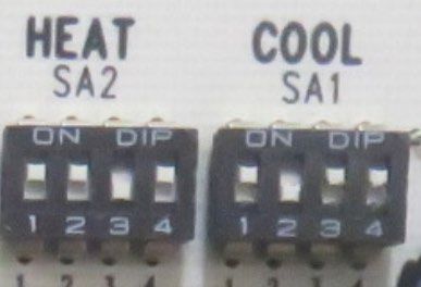
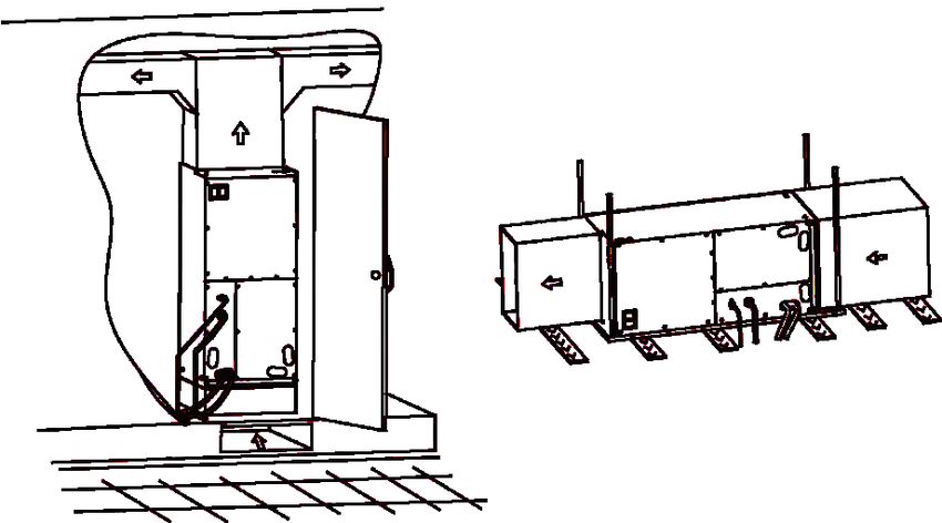
Table of Contents
SAFETY INFORMATION. . . . . . . . . . . . . . . . . . . . . . . . . . . . . . . . . . . . . . . . . . . . . . . . . . . . . . . . . . . . . . . . . . . . . . . . . 4

OVERVIEW. . . . . . . . . . . . . . . . . . . . . . . . . . . . . . . . . . . . . . . . . . . . . . . . . . . . . . . . . . . . . . . . . . . . . . . . . . . . . . . . . . . 6

ACCESSORIES. . . . . . . . . . . . . . . . . . . . . . . . . . . . . . . . . . . . . . . . . . . . . . . . . . . . . . . . . . . . . . . . . . . . . . . . . . . . . . . .6

REQUIRED TOOLS FOR INSTALLATION. . . . . . . . . . . . . . . . . . . . . . . . . . . . . . . . . . . . . . . . . . . . . . . . . . . . . . . . . . . 7

UNIT DIMENSIONS . . . . . . . . . . . . . . . . . . . . . . . . . . . . . . . . . . . . . . . . . . . . . . . . . . . . . . . . . . . . . . . . . . . . . . . . . . . . 8

MAIN PARTS . . . . . . . . . . . . . . . . . . . . . . . . . . . . . . . . . . . . . . . . . . . . . . . . . . . . . . . . . . . . . . . . . . . . . . . . . . . . . . . . . 9

INSTALLATION INSTRUCTIONS. . . . . . . . . . . . . . . . . . . . . . . . . . . . . . . . . . . . . . . . . . . . . . . . . . . . . . . . . . . . . . . . . 10

CONVENTIONAL LINE SET INSTALLATION. . . . . . . . . . . . . . . . . . . . . . . . . . . . . . . . . . . . . . . . . . . . . . . . . . . . . . . . 11

REFRIGERANT LINE INSTALLATION. . . . . . . . . . . . . . . . . . . . . . . . . . . . . . . . . . . . . . . . . . . . . . . . . . . . . . . . . . . . . 11

INSTALL CONDENSATE DRAIN . . . . . . . . . . . . . . . . . . . . . . . . . . . . . . . . . . . . . . . . . . . . . . . . . . . . . . . . . . . . . . . . . 12

ELECTRICAL REQUIREMENTS . . . . . . . . . . . . . . . . . . . . . . . . . . . . . . . . . . . . . . . . . . . . . . . . . . . . . . . . . . . . . . . . . 13

DUCT SYSTEM. . . . . . . . . . . . . . . . . . . . . . . . . . . . . . . . . . . . . . . . . . . . . . . . . . . . . . . . . . . . . . . . . . . . . . . . . . . . . . . 13

HEATER KIT. . . . . . . . . . . . . . . . . . . . . . . . . . . . . . . . . . . . . . . . . . . . . . . . . . . . . . . . . . . . . . . . . . . . . . . . . . . . . . . . . 14

ELECTRICAL CONNECTIONS . . . . . . . . . . . . . . . . . . . . . . . . . . . . . . . . . . . . . . . . . . . . . . . . . . . . . . . . . . . . . . . . . . 14

THERMAL EXPANSION VALVE. . . . . . . . . . . . . . . . . . . . . . . . . . . . . . . . . . . . . . . . . . . . . . . . . . . . . . . . . . . . . . . . . . 15

THERMOSTAT CONNECTION. . . . . . . . . . . . . . . . . . . . . . . . . . . . . . . . . . . . . . . . . . . . . . . . . . . . . . . . . . . . . . . . . . . 16

AIR FLOW ADJUSTMENT INSTRUCTIONS FOR CONNECT SERIES. . . . . . . . . . . . . . . . . . . . . . . . . . . . . . . . . . . . 18

FINAL CHECK. . . . . . . . . . . . . . . . . . . . . . . . . . . . . . . . . . . . . . . . . . . . . . . . . . . . . . . . . . . . . . . . . . . . . . . . . . . . . . . . 19

TROUBLESHOOTING . . . . . . . . . . . . . . . . . . . . . . . . . . . . . . . . . . . . . . . . . . . . . . . . . . . . . . . . . . . . . . . . . . . . . . . . . 19

LIMITED WARRANTY. . . . . . . . . . . . . . . . . . . . . . . . . . . . . . . . . . . . . . . . . . . . . . . . . . . . . . . . . . . . . . . . . . . . . . . . . . 21

Record Keeping
Thank you for purchase this product from GE Appliances, a Haier
company. This installation manual will help you to get the best
performance.                                                                                             _______________________________________
                                                                                                         Model number
For future reference, record the model and serial number located on
the label on the side of your air conditioner, and the date of purchase. _______________________________________
                                                                         Serial number
Staple your proof of purchase to this manual to aid in obtaining
warranty service if needed.                                              _______________________________________
                                                                         Date of purchase

To register your new air handler, go to
http://www.haierductless.com/product-registration and input the
model/serial number information on this page. To receive a 10-year
compressor and parts warranty, registration is required within 60
days of installation.

31-5000486 Rev. 2                                                                                                                                                                 3
IMPORTANT SAFETY INFORMATION
READ ALL INSTRUCTIONS BEFORE USING THE SYSTEM
WARNING For your safety, the information in this manual must be followed to minimize the risk of fire,
electric shock, or personal injury.
• Use this equipment only for its intended purpose as For any service which requires entry into the
described in this manual. refrigerant sealed system, Federal regulations
•T his air handler must be properly installed in require that the work is performed by a technician
accordance with these instructions before it is used. having a Class II or Universal certification.
•A ll wiring should be rated for the amperage value listed
on the rating plate. Use only copper wiring. •A
ll air conditioners contain refrigerants, which under
federal law must be removed prior to product disposal.
•A ll electrical work must be completed by a qualified
If you are disposing of an old product with refrigerants,
electrician and completed in accordance with local and
check with the company handling disposal.
national building codes.
•R
-410A systems require that contractors and technicians
•A ny servicing must be performed by a qualified
use tools, equipment and safety standards approved
individual.
for use with this refrigerant. DO NOT use equipment
certified for R22 refrigerant only.
WARNING RISK OF ELECTRIC SHOCK. Could cause injury or death.
•A
n adequate ground is essential before connecting the •R
epair or replace immediately all electrical wiring that
power supply. has become frayed or otherwise damaged. Do not use
•D
isconnect all connected electric power supplies before wiring that shows cracks or abrasion damage along its
installation or service. length or at either end.
WARNING RISK OF FIRE. Could cause injury or death.
•D
o not store or use combustible materials, gasoline or other flammable vapors or liquids in the vicinity of this or any
other appliance.
WARNING
This unit is not intended for use by persons (including The rated power supply of this product is 208/230
children) with reduced physical, sensory or mental VAC/60hz/1PH. Verify the voltage is within the 187~253
capabilities, or lack of experience and knowledge. range before turning the equipment on.
To avoid danger of suffocation, keep the plastic bag or Supply power to the air handler should be from a
thin film used as the packaging material away from young dedicated circuit that meets branch circuit ampacity
children. requirements.
Be sure not to allow foreign materials to enter the Use a special branch circuit breaker and disconnect
refrigerant piping. Seal the ends of refrigerant piping switch matched to the power circuit capacity of the air
before storage. handler. Install in accordance with national and local
For installation purposes, be sure to use the parts code.
supplied by the manufacturer or other prescribed parts.
The use of non-prescribed parts can cause serious
accidents such as the unit falling, water leakage, electric
shock, or fire.
4 31-5000486 Rev. 2IMPORTANT SAFETY INFORMATION
READ ALL INSTRUCTIONS BEFORE USING THE SYSTEM
CAUTION Regulation of cables and breaker differs from each
locality. Be aware of these regulations prior to installtion.
It is highly recommended that you do not open or close
the stop valves when the outdoor temperature is below Do not use existing refrigerant lines.
-5°F (-21°C), as this may cause refrigerant leakage. Use refrigerant tubing that is clean and free of any
Do not touch the fins of the coil. Touching the coil fins contamination which may cause damage to the system,
could result in damage to the fins or personal injury. including sulfur, copper oxide, dust, metal chips, powder,
oil, or water.
Ensure the power circuit capacity is adequate for all loads
connected to the electrical service panel. Increase the Avoid coupling lines whenever possible. Use a continuous
conductor and panel capacity if the total electrical loads length of copper tubing, as oxides formed during improper
exceed the power source capacity. brazing techniques can damage the equipment.
Contact the power utility if the power provided is below Do not use copper pipes that have a collapsed,
equipment rating plate requirements. deformed, or discolored portion (especially on the interior
surface). Otherwise, the expansion valve or capillary tube
Be sure to install a breaker of the specified capacity.
may become blocked with contaminants.
Refer to local requirements regarding type and kind of
Improper line sizing will degrade performance. Peak
breaker, power wiring, and control cable.
pressure of R410A is much higher than R22. Use ACR
copper tubing with adequate wall thickness.
Use a tubing bender to change piping direction. Make
sure the radius of the bend is no less than 4”.
If the pipe is bent repeatedly at the same place, it will
break.
SAVE THESE INSTRUCTIONS
FOR MORE HELP, VISIT HAIERAPPLIANCES.COM OR CALL THE CONSUMER HELP LINE AT 877-337-3639.
BEFORE YOU BEGIN CAUTION
Read these instructions completely and carefully.
• Aluminum electrical wiring may present special
• IMPORTANT – Save these instructions problems - consult a qualified electrician.
for local inspector’s use. • When the unit is in the STOP position, there is still
voltage to the electrical controls.
• IMPORTANT – Observe all governing
codes and ordinances.
• Note to Installer – Be sure to leave these instructions OUTDOOR REQUIUREMENTS
with the owner to use for future reference.
• Note to Owner – Keep these instructions for future There is a matching air handler and must be used with
reference. the outdoor units as rated by AHRI.
• Skill level – A licensed certified technician (to handle The outdoor sections are manufactured with an
refrigerant R-410A, recovery, etc.) and a qualified interchangeable refrigerant metering device for optimum
electrician are required for equipment and service of this refrigerant control and system performance. The AHRI
air handler system. rating may require the metering device be changed, in
• Use team lift for installation of this product. some cases, to meet the rated performance.
• Proper installation is the responsibility of the installer.
• Product failure due to improper installation is not covered
under the limited warranty.
• For personal safety, this system must be properly
grounded.
• Protective devices (fuses or circuit breakers) acceptable
for installation are specified on the nameplate of each unit.
• Piping or wiring within walls must be protected per local code.
31-5000486 Rev. 2 5Overview
It is the responsibility of the installer to ensure all please contact GE Appliances technical support. Provide
installation aspects of this product adhere to national, the following information:
state, and local codes.
a. Product Nameplate data (model number, cooling / heating
Every possible system difference or work site abnormality
capacity, product serial number, factory date)
cannot be addressed in this manual. If questions arise, it
is the obligation of the installer to contact the distributor or b. Nature of Malfunction (specify the circumstances before
supplier of this product for assistance. and after the error occurred)
To ensure proper performance, the duct system pressure 7. All illustrations and information in the instruction manual
drop should never exceed the static pressure capacity of are for reference only. We retain the right to make
the blower.
necessary revisions to the product from time to time.
Only use and apply accessory heater components that
are approved in this manual. 8. GE Appliances assumes no responsibility for personal
All work should be performed by persons trained, injury, property loss or equipment damage caused by
experienced, and licensed in the mechanical and improper installation and commissioning, unecessary
electrical fields. maintenance, or failure to follow relevant federal and state
The manufacturer will not be responsible for equipment regulations, industry standards, and the requirements of
that is under-performing due to a failure to follow the this instuction manual.
instructions in this manual or best industry practices.
9. G
E Appliances will bear no responsibilities for personal
The manufacturer has the right to revise this manual
without notice. injury or property damage caused by the following:
1. No person should operate, maintain, or service this a. Improper use of the appliance
equipment unless suitably trained by an industry b. Altering, maintaining, or operating the product with non-
professional. approved equipment.
2. Disconnect unit from the power supply if it not to be used c. Altering, maintaining, or operating the product outside of
for an extended period. the guidelines of this manual.
3. Be certain that you have selected the proper model for the d. Defects caused by corrosive gas.
operating load. Improper selection may impact operating e. Defects caused by shipping damage.
performance. f. Failure to abide by this instruction manual or government
4. Please do not disassemble the unit without proper regulations.
training. This equipment has undergone strict inspection g. Products made by other manufacturers
and operational testing at the factory. h. Natural disasters, improper installation environment, or
5. For technical assistance, please contact GE Appliances force majeure.
technical support
6. If the product is malfunctioning and/or is inoperable, Owner’s
Manual
Accessories
Owner’s
Part Looks Like Manual Quantity
Owner’s Manual 1
Owner’s
Manual
Optional Liquid Side Stub Kit 1
To connect the unit with the liquid pipe
Optional Gas Side Stub Kit 1
To connect the unit with the gas pipe
6 31-5000486 Rev. 2Installation Instructions
Required Tools for Installation
• 18-8 thermostat wire • Micron gauge
• 5/8” (16mm), 7/8” (22mm), 1” (25mm) or Adjustable • Mini-split adapter (5/16”F to 1/4”M)
Wrench • Nitrogen*
• R-410A Refrigerant* • Pipe cutter
• Adhesive tape* • PVC pipe
• Conduit cable clamp 1/2”* • Razor knife
• Copper line set (for size, see table on page 15) • Reamer
• #2 phillips screwdriver • Saddle clamp (L.S.) w/ screws
• Drill • Sealant, non-expanding (for lineset hole)
• R-410A flaring tool • Soap/water solution* or gas leakage detector
• Hex wrench • Stud finder
• Hole saw 2 1/4” • Torque wrench
• Insulation* • Vacuum pump
• Refrigerant scale • Wire strippers
• Level • All usual and customary HVAC hand and power tools,
• Manifold gauge set meters, and testing devices
• Measuring tape * consumable
31-5000486 Rev. 2 7Installation Instructions
Unit Dimensions
A
B
H
W D
Model Dimension
W D H A B
UUY24ZGDAA 21-1/4(540) 21-1/4(540) 48-1/4(1224) 11-5/8(295) 20(508)
UUY36ZGDAA
UUY48ZGDAA 24-3/4(630) 21-1/4(540) 57(1448) 11-5/8(295) 20(508)
UUY60ZGDAA
Installation Clearances
24” clearance is required for filter, coil, or blower removal and service access.
The air handler can be installed in a closet with a false bottom to form a return air plenum or be installed with a return
air plenum under the air handler.
8 31-5000486 Rev. 2Installation Instructions
Main Parts
Control Box
Assembly
Blower Wheel
Fan Motor
Secondary Drain Pan
Evaporator
Assembly
Primary Drain Pan
Model Cooling capacity (ton) Optional electric heater (kW)
UUY24ZGDAA 2.0 8
UUY36ZGDAA 3.0 8
UUY48ZGDAA 4.0 15
UUY60ZGDAA 5.0 15
Model Motor @ 230V ~, 60Hz
HP FLA
UUY24ZGDAA 1/2 2.1
UUY36ZGDAA
UUY48ZGDAA 1 3.2
UUY60ZGDAA
Model Filter Size
UUY24ZGDAA 20” x 20”
UUY36ZGDAA
UUY48ZGDAA 21” x 20”
UUY60ZGDAA
31-5000486 Rev. 2 9Installation Instructions
CAUTION WARNING
Prior to installation, turn off all electrical power supplies •T
his air handler is designed for indoor installation
intended for use with this equipment. only. Do not install it outdoors.
•W
hen installing the air handler, take consideration to
1. Checking Product Received minimize the length of refrigerant tubing as much as
After receiving the product, please check for any possible.
damage caused by transportation. Shipping damage
•W
hen installing in an area directly over a finished
is the responsibility of the carrier. Verify the model
ceiling (such as an attic), installation of an emergency
number, specifications, and accessories are correct
drain pan is required directly under the unit. See local
prior to installation. The distributor or manufacturer
and state code for requirements.
will not accept claims from dealers for transportation
damage or installation of incorrectly shipped units. •W
hen installing this unit in an area that may become
The manufacturer assumes no responsibility for the wet, elevate the unit with a sturdy,
installation of incorrectly delivered units. non-porous material. Install a protective barrier per
2. Before Installation code for installations that may be subject to damage,
such as a garage.
Carefully read all instructions for the installation prior
to installing. Make sure each step or procedure is •T
his air handler is designed for a complete supply
understood and any special considerations are taken and return duct system. DO NOT operate this product
into account before starting installation. Assemble all without attaching a completed duct system.
tools, hardware and supplies needed to complete the DO NOT install the air handler in a location above or
installation. Some items may need to be purchased below the outdoor unit that violates the instructions
separately. Make sure everything needed to install the provided with the outdoor unit. Service clearance is
product is on hand before starting. to take precedence. Allow a minimum of 24” service
3. Codes and Regulations clearance in front of the unit.
This product is designed and manufactured to comply • If this air handler is to be installed in an enclosed
with national codes. It is installer’s responsibilities space containing fossil fuel burning appliances,
to install the product in accordance with such codes vehicle exhaust emissions, or other potential carbon
and/or any prevailing local codes/regulations. The monoxide sources, all code requirements for these
manufacturer assumes no responsibilities for equipment conditions must be strictly followed. Carbon monoxide
installed in violation of any codes or regulations. emissions can be circulated throughout the occupied
4. Replacement Parts space by the air handler’s duct system, causing death
When reporting shortages or damages, or ordering or serious illness.
repair parts, give the complete product model and serial
numbers as stamped on the nameplate. Replacement Typical installation configurations as shown
parts are available through your contractor or local
distributor.
Upflow Horizontal Left
10 31-5000486 Rev. 2Installation Instructions
Conventional Line Set Installation Refrigerant Line Installation
Pipe Size Refrigerant lines must be connected by a licensed,
EPA certified refrigerant technician in accordance with
Model External Diameter (inch) established procedures.
Gas pipe Liquid Pipe IMPORTANT:
UUY24ZGDAA 3/4 3/8 • Connecting refrigerant lines must be clean,
UUY36ZGDAA dehydrated, refrigerant-grade copper lines. Air handler
UUY48ZGDAA coils should be installed only with specified line sizes
UUY60ZGDAA for approved system combinations.
Proper flaring is essential to achieve an airtight seal. • Use care with the refrigerant lines during the
1. Ensure there is enough insulation to protect the entire installation process. Sharp bends or possible kinking
line set from end to end. Use multiple light passes in the lines will cause a restriction.
when cutting tubing to the desired length, tightening • Do not remove the caps from the lines or system
the cutting wheel only until light resistance is felt. connection points unit connections are ready to be
Ream both outside and inside, holding tube down to completed.
keep reaming chips from falling into the tube. 1. Route the suction and liquid lines from the fittings on
2. Use the flare nuts from the accessories pouch, the indoor coil to the fittings on the outdoor unit. Run
located in the indoor unit packaging. Fit the nut on the lines in a direct path, avoiding unnecessary turns
the tubing to be flared. and bends.
Flare nut 2. Ensure that the suction line is insulated over the
entire exposed length and that both suction and
liquid lines are not in direct contact with floors, walls,
ductwork, floor joists, or other piping.
Copper pipe
3. Connect the suction and liquid line to the evaporator
coil.
4. To avoid damage; remove the TXV sensing bulb
3. Remove the seal over the exposed end, and place while brazing. Relocate rubber grommets away from
the tube into the R-410A flaring tool. the heat to avoid melting them.
5. Braze with an alloy of silver or cooper and
phosphorus with a melting point above 1,100°F.
NOTE: Do not use soft solder.
4. Run the tube against the flaring tool pipe stop, and
6. Reinstall the TXV sensing bulb and the rubber
clamp the form on the tube.
grommets after brazing is finished.
5. Rotate the handle of the die clockwise until the clutch
7. Make sure the outdoor air conditioning unit has been
releases, then remove the flared tubing from the form.
put in place according to the Installation Instructions
and is connected to the refrigerant lines.
While brazing, purge the system with Nitrogen to
prevent contamination. Manufacturer recommends
reattaching and insulating the TXV sensing bulb at a 10
or 2 o’clock position on the suction line, outside the coil
Flare form housing, no more than one foot from the connection.
A Evacuate the system to 500 microns to ensure proper
air and moisture removal (Note: Deep evacuation or
triple evacuation method recommended). Open the
suction service valve slowly and allow the refrigerant to
bleed into the system before opening the liquid service
Pipe valve.
A = ~1/16” (1.6mm)
6. Examine the flare to make sure there are no
imperfections on the lip of the flare, and that the back
of the flare exactly fits the seat of the flare nut.
31-5000486 Rev. 2 11Installation Instructions
Install Condensate Drain Install Condensate Drain (cont.)
The air handler is provided with 3/4” NPT condensate 1. P our several quarts of water into the drain pan,
drain connections. enough to fill drain trap and line.
A field fabricated secondary drain pan with a drain 2. Check to make sure the drain pan is draining
pipe to the outside of the building is required in all completely, no leaks are found in drain line fittings,
installations over a finished living space or in any area and water is draining from the end o the primary
that may be damaged by overflow from the main drain drain pan.
pa. In some localities, local codes require secondary 3. Correct any leaks found.
drain pan for any horizontal installations. The secondary Drain Line and Vent Tee
drain pan must have a larger footprint than the air
handler. Vent must extend a minimum of 2”
1. Remove the appropriate panel knockouts for drains. Clean Out
Press in
above the drain pan
See “Drain Pan Connections” section. You may need (DO NOT GLUE)
to remove the indoor coil assembly from the cabinet.
Vent
“T”
Drain Pan 2” Min.
2. Determine the drain connection to be used and
note differences between the primary (green) and
secondary (red) openings. Drain plugs are provided 3/4” MPT Connector
Drain Line
for all openings; remove and discard the appropriate
Reducing Tee with
plugs with 1/2” drive ratchet and verify that remaining 1” Slip Hex Plug 2” Min. Pitch horizontal
drain lines
plugs are tight (2.5 ft-lbs). Attach drain line to pan downward 1” per 10'
with 3/4” make pipe thread PVC fittings. Hand tight is Insulate pipe as needed
adequate—do not over tighten and do not reduce the
line size.
3. Secondary drain connections should be connected
to a separate drainage system. Run this drain to
a place in compliance with local installation codes
where is will be secondary drain indicates a plugged
primary drain.
4. Install a 2” trap in the primary drain line as close to
the unit as practical. Make sure the top of the trap
is below the connection to the drain pan to allow
complete drainage of the pan.
NOTE: Horizonal runs must also have an anti-siphon
air vent (standpipe) installed ahead of the horizontal
run. An extremely long horizontal run may require an
oversized drain line to eliminate air trapping.
NOTE: Do not operate air handler without a drain trap.
The condensate drain is on the negative pressure
side of the blower; therefore being pulled through the
condensate line will prevent positive drainage without a
proper trap.
5. Route the drain line to the outside or to an
appropriate drain. Drain lines must be installed so
they do not block serviceaccess to the front of the air
handler. A 24” clearance is required for filter, coil, or
blower removal and service access.
NOTE: Check local codes before connecting the drain
line to an existing drainage system.
6. Insulate the drain lines where sweating could cause
water damage.
Upon completeion of installation, it is the responsibility
of the installer to ensure the drain pan(s) is capturing
all condensate, and all condensate is draining properly
and not getting into the duct/system.
12 31-5000486 Rev. 2Installation Instructions
Electrical Requirements
Model Power Supply Recommended breaker
size (A)
UUY24ZGDAA
UUY36ZGDAA
208/230V-1Ph-60Hz 15
UUY48ZGDAA
UUY60ZGDAA
Control wiring” to “Electric wiring Wiring Connections
Using 18 Gauge Solid Core Copper Wire 1. High and low voltage wires should be led through
1. Cut back the insulation 1” from the end of the wire. different rubber rings of the electric box cover.
2. Remove the screw from the terminal block, and wrap 2. To avoid communication errors, maintain as much
the wire around the screw. separation as possible between the power and control
wiring.
3. Return the screw and wire to the terminal block and
tighten securely. 3. High and low voltage wires should be secured
separately. Secure the former ones with large clamps
and the latter ones with small clamps.
4. Use screws to tighten high and low voltage wiring on
1” (25mm)
the terminal board. Improper connection may create a
fire hazard.
5. Ground the units by connecting the ground wire.
6. All wiring must comply with local and national code.
Screw with
Special Fastener
Round
Terminal
Jacket / Insulation
Terminal
Stranded Wire Board
1. Cut back the insulation 3/8” from the end of the wire.
2. Make sure the round or forked terminal connector is Wire
rated for the amperage of the unit being installed.
3. Use a crimping tool only to fasten the connector to the
wire. Duct System
4. Return the screw and connector to the terminal block CAUTION
and tighten securely.
1. Ensure that the power supply is disconnected prior to
Solderless
Terminal installing the heater kit.
2. A
means of strain relief and conductor protection must
be provided at the supply wire entrance into cabinet.
3. Only use copper conductors.
4. Installation must follow The National Electrical Code
3/8” (10mm)
and other applicable codes.
5. If this appliance is installed in an enclosed area, such
as a garage or utility room with any carbon monoxide
producing appliance, ensure that area is properly
ventilated to the outside.
31-5000486 Rev. 2 13Installation Instructions
Heater Kit Electrical Connections
1. Refer to the table for the appropriate heater kit.
Connect to 8kw heater Circuit Breaker
2. Check for any physical damage; do not install a
damaged heater kit. Air Handler Supply Voltage
3. Remove the upper access panel from the air handler.
Wire Connections
4. Remove cover plate from air handler.
Field Supply
5. Slide the heater kit into the slot and secure element Ground Wires
208/230 Volt
plate with previously removed screws. Field Supply Wires
6. Insert power leads into the circuit breaker lugs or
stripped red and black wires (for heater kit without
circuit breaker) and tighten.
7. Connect ground wire to ground lug.
8. Knock off appropriate area of the plastic circuit
breaker cover on the access panel of the air handler.
Connect to 15kw heater Circuit Breaker
Knock off the holes according to the actual installation Air Handler Supply Voltage
number and positions of circuit breakers. If circuit Wire Connections
breaker is not installed, do not knock off the holes,
otherwise there maybe has electric shock occur.
Field Supply
9. Replace access panel and check operation. Ground Wires
208/230 Volt
Field Supply Wires
10. Finalize power and control wiring.
Cover Plate
Bolt
Heater Kit Connect to Terminal Block
Air Handler Supply Voltage Wire Connections
Circuit Breaker
Fig 2.9 Field Supply
Ground Wires L2
208/230 Volt
Field Supply Wires
L1
ATTENTION: If it is new air handler and it is the first
time install heat, make sure the L1/L2 wire to heater
breaker, then wire the ground wire. Use proper wire
size as specified in this manual for 8K and 15 K heater
assemblies.
If there is no heat kit to install, please make sure wire to
Kit # Description terminal block.
UAZEH08A 8kW Heater with 45A breaker
UAZEH15A 15kW Heater with 30A and 60A
breakers
14 31-5000486 Rev. 2Installation Instructions
Thermal Expansion Valve (TXV)
Factory Installed Expansion Valves: Sensing bulbs are
factory installed and clamped to the suction line. For
optimum performance, reattach and insulate the bulb
at a 10 or 2 o’clock position outside of the cabinet to
the main suction line no more than one foot from the
suction line connection. If necessary, the bulb can be
installed on a vertical suction line. In this instance, the
bulb must be placed before any trap, with the bulb’s
capillary tube facing upward.
Thermal Expansion Valve (Letter A)
NOTE: Some models are equipped with thermo expansion
valve and do not require any orifice change.
NOTE: The coil comes pre-charged with refrigerant
R410A. The coil must be evacuated if the TXV valve is
changed.
31-5000486 Rev. 2 15Installation Instructions
Thermostat Connections
See Note
G
CB1 CB1
XT1 8kw Heat Kit
L1 L1 X1 X1
Power L2 L2
G
Indoor Unit Note:
XT2 1. Please refer to the Instruction Manual to check
Y Y
B B whether the unit can connect to the engineerig
W1 W1 electric heating.
Thermostat
R R 2. When the unit doesn't connect to the engineering
C C
G
electric heating, connect the engineering power
G
supply to the L1 and L2 of wiring board.
3. When the unit connects to the engineering electyric
heating, connect the engineering power supply to
the breaker.
XT1
L1 L1
Power L2 L2
G
XT2 Outdoor Unit
Y
B
W1
R
C
G
ATTENTION: Thermostat must energize reversing valve in heat mode using the “B” terminal.
Indoor Unit - 2/3 ton
Power L1 G L2
L1 W5
G
W6 CB1 Heat CB1
L2
XT1
G
1
W3
1 X1
G 1 2 3 4 5 6
W4
N 2
X1
W1 W2
8KW HEAT KIT
Y
XT2 Y Y
Y
W7 W8 X1 X2 W12
B B B
AP2
B W13 CN1 COM2
X10
W1 W1 W1
DC_MOTOR1 Code Name
CB1 Circuit breaker
W1
TC Transformer
W9 AP1
R R R
Thermostat XT1~XT3 Wiring board
X4
R Fan motor Y
RDXT1-1 4-way valve control
W10 M
C C C
C X3 B signal, energized under
X9 X13X7 BKXT1-2 the heating mode
W11 ① YEGN W1 Heater control signal
G G
G XT3 1 R 24V AC power supply
G
WHTCBU C 24V common
BK G Indoor unit fan signal
YE RD
Note:
1. Please refer to the instruction manual to check whether the unit can connect to the engineering electric heating.
2. When the unit doesn’t connect to the engineering electric heating, connect the engineering power supply to the W5(BK) and W6(WH) of X1.
3. When the unit connects to the engineering electric heating, connect the engineering power supply to the breaker.
4. The primary input voltage of transformer is defaulted at 230V(BK). When switching the power supply of the complete unit to 208V, connect the
primary input voltage of transformer to 208V(BU), which can be realized by exchanging the black wire and the blue wire.
5. 1 Only applicable for the unit whose motor is with earthing wire.
16 31-5000486 Rev. 2Installation Instructions
Indoor Unit - 4/5 ton
L1 G L2
Power
L1 W5 G
CB1 CB2 CB2 CB1
W6 Heat
L2
XT1
G
1
W3
1 X1
G 1 2 3 4 5 6
W4
N 2
W14
X1
W1 W2 15KW Heat kit
Y
XT2 Y Y
Y
W7 W8 X1 X2 W12
B B B
4 Code Name
B W13 CN1 COM2 AP2 CB1
Circuit breaker only for
X10 10KW heat kit
W1 W1 W1
DC_MOTOR1 Circuit breaker only for
CB2
W1 5KW heat kit
TC Transformer
W9 AP1 4
R R R
Thermostat X4 XT1~XT3 Wiring board
R Y
W10 Fan RD XT1-1 4-way valve control
C C C
X3 M B signal, energized under
C X9 X13 X7 motor
BK XT1-2 the heating mode
W11 W1 Heater control signal
G G
G XT3 1 YEGN R 24V AC power supply
WHTC BU ① C 24V common
BK G G Indoor unit fan signal
Note: YE RD
1. Please refer to the instruction manual to check whether the unit can connect to the engineering electric heating.
2. When the unit doesn’t connect to the engineering electric heating, connect the engineering power supply to the W5(BK) and W6(WH) of X1.
3. When the unit connects to the engineering electric heating, connect the engineering power supply to the breaker.
4. The primary input voltage of transformer is defaulted at 230V(BK). When switching the power supply of the complete unit to 208V, connect the
primary input voltage of transformer to 208V(BU), which can be realized by exchanging the black wire and the blue wire.
5. 1 Only applicable for the unit whose motor is with earthing wire.
6. As for wiring, please refer to the parameters before “ /” of MCA and MOP of heat kit on the nameplate for CB1; please refer to parameters after “ /”
of MCA and MOP for CB2.
31-5000486 Rev. 2 17Installation Instructions
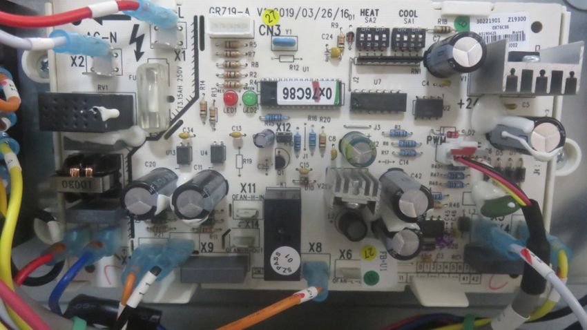
Airflow Adjustments Instructions for Connect Series
Default airflow setting of air handler is in speed 1. It can be adjusted by using the control board dip switch to different speed
according to Water static(Pa). Operation Instruction is below:
1. Dip switch settings must be completed before power on the unit.
2. Airflow dip switch is indicated by the red circle.
DIP Switch Configuration
Model Level Heat (SA2) Cool (SA1)
UUY24ZGDAA Speed 1-CFM (L) Default ON OFF ON OFF ON OFF ON OFF
Speed 2-CFM (M) ON OFF OFF ON ON OFF OFF ON
Speed 3-CFM (H) ON OFF OFF OFF ON OFF OFF OFF
UUY36GDAA Speed 1-CFM (L) Default ON ON OFF ON ON ON OFF ON
Speed 2-CFM (M) ON ON OFF OFF ON ON OFF OFF
Speed 3-CFM (H) ON OFF ON ON ON OFF ON ON
UUY48ZGDAA Speed 1-CFM (L) Default OFF ON OFF OFF OFF ON OFF OFF
Speed 2-CFM (M) OFF OFF ON ON OFF OFF ON ON
Speed 3-CFM (H) OFF OFF ON OFF OFF OFF ON OFF
UUY60GDAA Speed 1-CFM (L) Default OFF ON ON ON OFF ON ON ON
Speed 2-CFM (M) OFF ON ON OFF OFF ON ON OFF
Speed 3-CFM (H) OFF ON OFF ON OFF ON OFF ON
Blower Performance Data
Model Static Pressure - 0 0.1 0.15 0.2 0.3 0.4 0.5
Inches W.C.
UUY24ZGDAA Speed 1-CFM (L) 1050 940 910 850 720 - -
Speed 2-CFM (M) 1200 1070 1010 950 820 630 -
Speed 3-CFM (H) 1280 1180 1130 1080 970 790 660
UUY36ZGDAA Speed 1-CFM (L) 1230 1100 1000 950 900 - -
Speed 2-CFM (M) 1315 1230 1190 1145 1050 900 -
Speed 3-CFM (H) 1430 1325 1275 1225 1120 1050 900
Model Static Pressure - 0 0.1 0.2 0.3 0.4 0.5 0.6
Inches W.C.
UUY48ZGDAA Speed 1-CFM (L) 1650 1550 1470 1320 1210 - -
Speed 2-CFM (M) 1830 1730 1580 1500 1400 1280 -
Speed 3-CFM (H) 2000 1915 1810 1700 1590 1480 1350
UUY60ZGDAA Speed 1-CFM (L) 1850 1750 1600 1540 1440 - -
Speed 2-CFM (M) 2020 1930 1830 1730 1630 1530 -
Speed 3-CFM (H) 2100 2050 1950 1840 1750 1640 1580
18 31-5000486 Rev. 2Installation Instructions
Final Check
System Test Check Items for Test Run
Please explain to the customer how to operate the system
by using the Owner’s Manual found with the indoor unit. No gas leak from linesets?
Are the linesets insulated properly?
Are the connecting wirings of indoor and outdoor firmly
inserted to the terminal block?
Is the connecting wiring of indoor and outdoor fixed?
Explaining Operation To the End User Is condensate draining correctly?
• Using
the User Manual, explain to the user how to use
Is the ground wire securely connected? Is the indoor
the air conditioner/heat pump, (the remote controller, unit securely fixed?
adding/removing the air filters, placing or removing
Is power source voltage correct according to local
the remote controller from the remote control holder, code?
cleaning methods, precautions for operation, etc.)
Is there any odd noise?
• Review
precautions for operation. Does the cooling temperature drop between 20-30°F?
• Recommend
that the user read the Operating Does the heating temperature raise between 30-40°F?
Instructions carefully. Is the room temperature display accurate?
Troubleshooting
Problem Possible Causes Solution
The unit cannot be The unit is not connected to the power supply Connect to power supply
turned on. Low voltage Check if circuit voltage is within rated scope.
The fuse is broken or the breaker shorted out Replace fuse or connect breaker
The unit operates but Air inlet/outlet of indoor unit is blocked. Remove obstacles.
stops immediately.
Abnormal cooling or Air inlet/outlet of indoor unit is blocked. Remove obstacles.
heating. Inaccurate temperature setting. Adjust setting at wired controller.
Doors or windows are opened. Close the door or windows.
Direct sunshine. Draw curtain or louver.
Too much heat source in the room. Reduce heat source.
Filter screen is blocked by dirt. Clean the filter.
Unit doesn’t run. When unit is started immediately after it is Overload protection switch makes it run after
just turned off. 3 minutes delay.
When power is turned on. Standby operating for about 1 minute.
Mist comes from the Under cooling. Indoor high humidity air is cooled rapidly.
unit.
The unit is making Slight cracking sound is heard when just It is noise when electronic expansion valve
noises turned on. initialization.
There is consecutive sound when cooling. That’s sound for gas refrigerant flowing in the
unit.
There is sound when unit starts or stops. That’s sound for gas refrigerant stops flowing.
There is slight and consecutive sound when That’s sound for operation of drainage
unit is running or after running. system.
The unit blows out dust. When unit runs after no operation for a long Dust in indoor unit is blew out.
period.
The unit smells Operating. The room odor absorbed by the unit is blew
abnormal out again.
Indoor unit still runs After every indoor unit receive “stop” signal, Indoor fan can be set as “ON” or “AUTO”
after switch off. fan will keep running. mode. Under “ON” mode, indoor fan will keep
running after switch off the unit.
31-5000486 Rev. 2 19Notes 20 31-5000486 Rev. 2
Limited Warranty
For the product models listed on Attachment 1 (the “Product”), this Standard Limited Warranty is provided to the Original
Owner of the Product:

  For The Period Of:          Haier Will Replace:
  5 year limited parts        This limited warranty cover all defects in workmanship or material for the mechanical and
  warranty                    electrical parts contained in the Product (“Defective Parts”) for a period of 5 years from the
  From the date of the        Date of Purchase. Haier will provide new or refurbished parts, or a replacement for all or part
  original purchase           of the unit, at its sole discretion, to your licensed HVAC technician installer. This warranty also
                              covers all defects in workmanship or material for the unit controller for a period of 1 year. The
                              remote controller is covered by 1-year accessory warranty. The ductless system is covered
                              by standard warranty. Haier will provide a new or refurbished controller, at its sole discretion.
  7 year compressor      The compressor contained in this product is warrantied for a period of 7 years from the Date of
  warranty from the date Purchase. Haier will provide a new or refurbished compressor, or a replacement for all or part
  of the original purchase    of the unit, at its sole discretion, to your licensed HVAC technician installer.

WHAT IS THE DATE OF PURCHASE
The “Date of Purchase” is the date that the original installation is complete and all product start-up procedures have been
properly completed and verified by the installer’s invoice. If the installation date cannot be verified, then the Date of Purchase
will be sixty (60) days after the manufacture date, as determined by the Product’s serial number. You should keep and be
able to provide your original sales receipt from the installer as proof of the Date of Purchase. In new construction, the Date of
Purchase will be the date the owner purchased the residence from the builder.
WHO IS COVERED
Owner occupied: The “Original Owner” of this product, which means the original owner (and his or her spouse) of the residence
where the Product was originally installed. Subject to the law of the state or province where the Product is installed, this warranty
is not transferable to subsequent owners or if the product is moved to a different residence after the initial installation. Non-
owner occupied: This limited warranty is provided for product 1) installed in a) single family or multi-family non-owner occupied
residential buildings, or b) non-industrial commercial applications, (such as office buildings, retail establishments, hotels/motels)
where the product is not subjected to an atmosphere with corrosives or high levels of particulates (such as soot, aerosols, fumes,
grease), and 2) if the product is maintained annually by a licensed HVAC technician (proof of annual maintenance is required).
The “Original Owner” of the product, means the original owner of the building where the product was originally installed. For
new construction, the purchaser of the building from the builder will also be considered an original owner. This warranty is not
transferable to subsequent owners or if the product is moved to a different location after the initial installation.

HOW CAN YOU GET SERVICE
Contact your licensed HVAC technician installer. All installation and service must be performed by a licensed HVAC
technician. Failure to use a licensed HVAC technician for installation of this Product voids all warranty on this Product.

THIS WARRANTY DOES NOT COVER
                                                                                                                                 date is needed to obtain service under the warranty.
                                                                                                                                 Staple your receipt here. Proof of the original purchase
• Damage from improper installation.                              • Batteries for the controller and other accessories
• Damage in shipping.                                               provided with the Product for installation (e.g., plastic
• Defects other than from manufacturing (i.e., workmanship         hose).
   or materials).                                                 • Normal maintenance, such as cleaning of coils, cleaning
• Damage from misuse, abuse, accident, alteration, lack            filters, and lubrication.
   of proper care and/or regular maintenance, or incorrect        • For Product installed in non-owner occupied applications,
   electrical voltage or current.                                   Product that has not been maintained annually by a
• Damage resulting from floods, fires, wind, lightning,            licensed HVAC technician (proof required).
   accidents or similar conditions.                               • Damage caused by a used or unapproved component
• Damage from installation or other services performed by          or part by GE Appliances, a Haier company (e.g., a used
   other than a licensed HVAC technician.                           and/or unapproved condenser / air handler).
• Labor and related services for repair or installation of the   • Component or parts are not provided by GE Appliances,
   Product.                                                         a Haier Company
• A Product purchased from an online retailer.
• Damage as a result of subjecting Product to an
   atmosphere with corrosives or high levels of particulates
   (such as soot, aerosols, fumes, grease).
• A Product sold and/or installed outside of the 50 United
  States, the District of Columbia, or Canada.

31-5000486 Rev. 2                                                                                                                               21
Limited Warranty 10 YEAR STANDARD REGISTERED LIMITED WARRANTY All “Indoor and Outdoor Products,” identified in Attachment 1, registered by the installer or the Original Owner within 60 days of the Date of Purchase shall receive a Standard Registered Limited Warranty, which shall be identical to the Standard Base Warranty, except that the Limited Parts Warranty shall be for a term of 10 Years and the Limited Compressor Warranty shall be for a term of 10 years. All Product not registered within 60 days of the Date of Purchase shall be subject to the Standard Base Warranty. Some states and provinces do not allow warranty terms to be subject to registration; in those states and provinces the longer terms for Limited Parts Warranty and the Limited Compressor Warranty apply. THIS LIMITED WARRANTY IS GIVEN IN LIEU OF ALL OTHER WARRANTIES, EXPRESS OR IMPLIED, INCLUDING THE WARRANTIES OF MERCHANTABILITY AND FITNESS FOR A PARTICULAR PURPOSE. The remedy provided in this warranty is exclusive and is granted in lieu of all other remedies. This warranty does not cover incidental or consequential damages. Some states and provinces do not allow the exclusion of incidental or consequential damages, so this limitation may not apply to you. Some states and provinces do not allow limitations on how long an implied warranty lasts, so this limitation may not apply to you. This warranty gives you specific legal rights and you may also have other rights which vary by state and province. This warranty covers units within the 50 United States, the District of Columbia and Canada. This warranty it provided by GE Appliances a Haier company, Louisville, KY 40225. ATTACHMENT 1 The product is defined as product sold by GE Appliances, a Haier Company. The product containers 2 sub-categories of goods, indoor and outdoor products, which are defined as AUH**, AHY**, UUH**, UUY***, UUC**, UUH* 22 31-5000486 Rev. 2
Instructions                                             Unité de
  d’installation                                       traitement d’air

Le fabricant recommande d’installer un système
intérieur et extérieur assorti répertorié AHRI.
L’installation d’un système intérieur et extérieur         LISEZ ET CONSERVEZ CES
apparié approuvé fournira une efficacité optimale et
la meilleure fiabilité globale du système.
                                                                     INSTRUCTIONS
                                                               31-5000486 Rev. 2 08-20 GEA
Renseignements De Référence
Merci d’acheter ce produit Haier. Ce manuel d’utilisation vous ai- _______________________________________
dera à obtenir le meilleur rendement de votre nouveau climatiseur. Numéro de modèle
Pour référence ultérieure, inscrivez les numéros de modèle et de _______________________________________
série sur l’étiquette située sur le côté de votre climatiseur ainsi Numéro de série
que la date d’achat.
_______________________________________
Agrafez votre preuve d’achat à ce manuel pour faciliter le service Date d’achat
de la garantie en cas de besoin.
Pour enregistrer votre nouveau système sans conduit Haier, allez
sur la page http://www.haierductless.com/product-registration et
entrez les numéros de modèle et de série sur cette page. Vous
devez enregistrer votre produit dans les soixante (60) jours suiv-
ant l’installation afin de vous prévaloir de la garantie de dix (10)
ans sur le compresseur et les pièces.
Ce manuel contient les instructions d’installation pour les unités intérieures en hauteur.
Pour la série FlexFit utilisant des unités intérieures de style différent, reportez-vous aux
manuel d’utilisation fourni avec l’unité intérieure pour les instructions d’installation.
31-5000486 Rev. 2 3CONSIGNES DE SÉCURITÉ IMPORTANTES
LISEZ TOUTES LES INSTRUCTIONS AVANT D’UTILISER LE SYSTÈME
AVERTISSEMENT
Pour votre sécurité, les renseignements dans ce manuel doivent être observés afin de minimiser le
risque d’incendie, de décharge électrique ou de blessure.
•U tilisez cet équipement uniquement aux fins auxquelles il est Si une réparation exige de pénétrer dans le système de
fait mention dans ce manuel d’utilisation. frigorigène étanche, la réglementation fédérale impose de
• Avant son utilisation, ce climatiseur doit être installé faire réaliser le travail par un technicien de Classe II ou
correctement en conformité avec les instructions d’installation. détenant une certification universelle.
• Tout le câblage doit présenter des valeurs nominales
• Tous les climatiseurs contiennent un frigorigène qu’il faut retirer
compatibles avec l’alimentation électrique spécifiée sur la
avant de disposer du produit en vertu de la loi fédérale. Si
plaque signalétique. Utilisez seulement du fil de cuivre.
vous vous débarrassez d’un produit qui contient un frigorigène,
• Toute la partie électrique de l’installation doit être exécutée informez-vous auprès de l’organisme responsable d’en disposer.
par un électricien agréé selon les codes de l’électricité local et
•C
es systèmes de climatisation R-410A exigent que les
national.
entrepreneurs et les techniciens utilisent des outils, des
• Toute réparation doit être effectuée par une personne qualifiée. équipements et des normes de sécurité approuvés pour ce type
de frigorigène. N’utilisez PAS un équipement certifié pour le
frigorigène R22 seulement.
AVERTISSEMENT RISQUE DE CHOC ÉLECTRIQUE. Peut occasionner une blessure ou la mort.
•U
ne mise à la terre est essentielle avant de brancher •R
éparez ou remplacez immédiatement tout câblage électrique
l’alimentation électrique. usé ou autrement endommagé. N’utilisez pas un câblage
•C
oupez l’alimentation électrique à la source avant de procéder qui présente des fissures ou des marques d’abrasion sur sa
longueur ou l’une de ses extrémités.
à une réparation ou un entretien.
AVERTISSEMENT RISQUE D’INCENDIE. Peut occasionner une blessure ou la mort.
•A
bstenez-vous d’entreposer ou d’utiliser des matières combustibles, de l’essence ou d’autres vapeurs ou liquides inflammables à
proximité de cet appareil ou de tout autre.
AVERTISSEMENT L’alimentation électrique nominale de ce produit est de
208/230 VCA/60Hz/1PH. Vérifiez que la tension se situe
Cet appareil n’est pas destiné à être utilisé par des
entre 187 et 253 V avant de mettre l’équipement sous
personnes (y compris les enfants) dont les capacités
tension.
physiques, sensorielles ou mentales sont réduites, ou
manquant d’expérience et de connaissance, sauf si elles L’alimentation électrique à la pompe à chaleur doit provenir
sont étroitement surveillées et instruites sur l’utilisation de d’un circuit dédié qui satisfait les exigences en courant
l’appareil par une personne responsable de leur sécurité. admissible d’un circuit de dérivation.
Les enfants doivent être surveillés afin de s’assurer qu’ils ne Utilisez un disjoncteur et une prise de circuit de
jouent pas avec l’électroménager. dérivation spéciaux qui correspondent à la capacité du
Pour prévenir le risque de suffocation, gardez à l’écart des circuit d’alimentation de la pompe à chaleur. (Installez
enfants les sacs ou les pellicules en plastique utilisés pour conformément aux normes techniques locales relatives aux
l’emballage. équipements électriques.)
Assurez-vous de ne pas laisser pénétrer des matières N’utilisez pas de rallonge de cordon électrique.
étrangères (huile, eau, etc.) dans la tuyauterie de réfrigérant. Exécutez le câblage en satisfaisant les normes en vigueur
Scellez les extrémités de la tuyauterie de réfrigérant avant le de façon à utiliser le climatiseur d’un manière sûre et
remisage positive.
À des fins d’installation, assurez-vous d’utiliser les pièces Installez un disjoncteur de fuite à la terre conformément aux
fournies par le fabricant ou d’autres pièces prescrites. lois et réglementations en vigueur ainsi qu’aux normes du
L’utilisation de pièces non prescrites peut entraîner de fournisseur d’électricité.
graves accidents tels que la chute de l’appareil, les fuites
d’eau, la décharge électrique ou l’incendie.
4 31-5000486 Rev. 2CONSIGNES DE SÉCURITÉ IMPORTANTES
LISEZ TOUTES LES INSTRUCTIONS AVANT D’UTILISER LE SYSTÈME
N’utilisez pas les conduites de réfrigérant existantes.
ATTENTION
Il est fortement recommandé de ne Utilisez une tuyauterie de réfrigérant qui est propre et exempte
pas ouvrir ou fermer les robinets d’arrêt lorsque la température de contamination pouvant causer des dommages au système,
extérieure est en dessous de -5 °F (-21 °C) car cela pourrait y compris les éléments suivants : souffre, oxyde de cuivre,
causer une fuite de réfrigérant. poussière, fragments de métal, poudre, huile ou eau.
Assurez-vous que l’appareil est sous tension durant au moins Évitez de braser les conduites ensemble. Utilisez une longueur
12 heures après des périodes de mise hors tension dans un de tuyau de cuivre continue étant donné que les oxydes
environnement de 32 °F (0 °C) ou plus froid. produits par une technique de brasage incorrecte peuvent
endommager l’équipement.
Ne touchez pas aux ailettes du serpentin. Toucher aux ailettes
risque de les endommager ou d’occasionner une coupure de la N’utilisez pas de tuyaux de cuivre dont une partie s’est
peau. effondrée, déformée ou décolorée (en particulier la surface
intérieure). Autrement, des contaminants peuvent bloquer le
Assurez-vous que la capacité du circuit d’alimentation est
détendeur ou le tube capillaire.
adéquate pour toutes les charges connectées au panneau de
branchement électrique. Augmentez la capacité du conducteur Un dimensionnement incorrect de la tuyauterie va diminuer
et du panneau si le total des charges électriques excède la le rendement. Les pointes de pression du réfrigérant R410A
source d’alimentation électrique. sont beaucoup plus élevées que celles du R22. Utilisez une
tuyauterie en cuivre dont l’épaisseur des parois est adéquate.
Contactez le fournisseur d’électricité si l’alimentation électrique
est en-dessous des spécifications inscrites sur la plaque Évitez les courbures abruptes afin de prévenir
signalétique de l’équipement. l’endommagement du tuyau. Courbez le tuyau selon un rayon
de courbure de 4 po (100 mm) ou plus.
Assurez-vous d’installer un disjoncteur de la capacité requise.
Le tuyau se brisera s’il est courbé à répétition au même endroit.
La réglementation relative aux câbles et aux disjoncteurs diffère
selon les régions, il faut donc respecter les codes locaux.
LISEZ ET CONSERVEZ CES INSTRUCTIONS
POUR OBTENIR DE L’AIDE SUPPLÉMENTAIRE, VISITEZ HAIERAPPLIANCES.COM OU COMMUNIQUEZ AVEC
L’ASSISTANCE AU CONSOMMATEUR AU 877-337-3639.
AVANT DE COMMENCER ATTENTION
Veuillez lire toutes ces instructions attentivement.
• IMPORTANT – Conservez ces instructions à •
Le câblage électrique en aluminium peut présenter des
problèmes particuliers, veuillez consulter un électricien
l’usage de l’inspecteur local. agréé.
• IMPORTANT – Observez tous les codes et
• Le
câblage de bâtiment en aluminium peut présenter des
problèmes particuliers, veuillez consulter un électricien
ordonnances en vigueur.
agréé.
• Note à l’installateur – Assurez-vous de laisser ces instructions au
consommateur.
• Note au consommateur - Conservez ces instructions pour
référence ultérieure.
• Niveau de compétence – Un technicien (pour manipuler le
frigorigène R-410A, récupération, etc.) et un électricien agréés sont
requis pour l’installation y servicio de ce climatiseur à deux blocs.
• L’exactitude de l’installation est la responsabilité de l’installateur.
• La garantie ne couvre pas les défectuosités du produit causées
par une installation inadéquate.
• Pour votre sécurité, ce produit doit être correctement mis à la terre.
• Les dispositifs de protection (fusibles ou disjoncteurs) admissibles
pour l’installation sont spécifiés sur la plaque signalétique de
chaque unité.
. • Si une réparation exige de pénétrer dans le système de
frigorigène étanche, la réglementation fédérale impose de faire
réaliser le travail par un technicien de Classe II ou détenant une
certification universelle.
31-5000486 Rev. 2 5You can also read