Waterpolo Equipment - Racing Lane Lines - FINA
←
→
Page content transcription
If your browser does not render page correctly, please read the page content below
Waterpolo
         Equipment

                                     Racing
                                   Lane Lines

           We are proud to be selected
     for important events all over the world.

Selected When it Counts

       Follow us on social media

                                        www.malmsten.com
FACILITIES RULES 2017 – 2021

                                   PART X

                     FINA FACILITIES RULES
                                 2017– 2021

                      PREAMBLE

         FR 1         GENERAL

         FR 2         SWIMMING POOLS

         FR 3         SWIMMING POOLS FOR OLYMPIC GAMES
                      AND WORLD CHAMPIONSHIPS

         FR 4         AUTOMATIC OFFICIATING EQUIPMENT

         FR 5         DIVING FACILITIES

         FR 6         DIVING FACILITIES FOR OLYMPIC GAMES
                      AND WORLD CHAMPIONSHIPS

         FR 7         POOLS FOR WATER POLO

         FR 8         WATER POLO POOLS FOR OLYMPIC GAMES
                      AND WORLD CHAMPIONSHIPS

         FR 9         EQUIPMENT FOR WATER POLO POOLS

         FR 10        POOLS FOR ARTISTIC SWIMMING

         FR 11        POOLS FOR ARTISTIC SWIMMING IN OLYMPIC GAMES
                      AND WORLD CHAMPIONSHIPS

         FR 12        AUTOMATIC OFFICIATING EQUIPMENT

         FR 13        SOUND EQUIPMENT AND PRESENTATION STANDARDS

         FR 14        HIGH DIVING FACILITIES

Version 28.01.2020                                                             1
FACILITIES RULES 2017 – 2021

PREAMBLE

         The Facilities Rules are intended to provide the best possible environment for competitive
         use and training. These Rules are not intended to govern issues related to the general public.
         It is the responsibility of the owner or controller of a facility to provide supervision for
         activities undertaken by the general public.

FR 1     GENERAL

         FR 1.1      FINA Olympic Standard Pools.
         All World Championships (except the Masters World Championships) and Olympic Games must
         be held in pools that comply with Rules FR 3, FR 6, FR 8, and FR 11.

         FR 1.2      FINA General Standard Pools.
         Other FINA events should be held in FINA Olympic Standard Pools, but the Bureau may waive
         certain standards for existing pools if they do not materially interfere with the competitions.

         FR 1.3      FINA Minimum Standard Pools.
         All other events held under FINA Rules should be conducted in pools that comply with all of the
         minimum standards contained within these Facilities Rules.

         FR 1.4       In order to protect the health and safety of persons using swimming facilities for the
         purposes of recreation, training and competition, owners of public pools or pools restricted only to
         training and competition must comply with the requirements established by law and the health
         authorities in the country where the pool is situated.

         FR 1.5      New competition equipment (e.g. Starting blocks, lane-ropes, etc.) must be available by
         1st January in the year of the Olympic Games and FINA World Championships.

FR 2     SWIMMING POOLS

         FR 2.1      Length

                     FR 2.1.1 50.000 metres. When touch panels of Automatic Officiating Equipment
                     are used on the starting end, or additionally on the turning end, the pool must be of
                     such length that ensures the required distance of 50.000 metres between the two
                     panels. See Swimming Diagram SW 1

                     FR 2.1.2 25.000 metres. When touch panels of Automatic Officiating Equipment
                     are used on the starting end, or additionally on the turning end, the pool must be of
                     such length that ensures the required distance of 25.000 metres between the two
                     panels. See Swimming Diagram SW 6, SW 7

Version 28.01.2020                                                                                         2
FACILITIES RULES 2017 – 2021

         FR 2.2      Dimensional Tolerances

                     FR 2.2.1   50m swimming pools.

                     The admissible tolerance in 50.00 m swimming pools will be +0.010, -0.000 metre
                     when touch panels are installed.

                     Tolerances will be measured as follows:

                     For swimming pools with touch panels of Automatic Officiating Equipment on
                     both ends the Wall to Wall distance shall be: Minimum 50.020 metre / Maximum
                     50.030 metre.
                     Tolerances have to be consistent 0.300 metre above to 0.800 metre bellow the
                     water surface.
                     These measurements should be certified by a surveyor or other qualified official,
                     appointed or approved by the Member in the country in which the pool is situated.
                     See Swimming Diagram SW 1

                     FR 2.2.2   25m swimming pools.

                     The admissible tolerance in 25.00 m swimming pools will be +0.010, -0.000 metre
                     when touch panels are installed.

                     Tolerances will be measured as follows:

                     For swimming pools with touch panels of Automatic Officiating Equipment on
                     both ends the Wall to Wall distance shall be: Minimum 25.020 metre / Maximum
                     25.030 metre.
                     For swimming pools with a touch panel of Automatic Officiating Equipment
                     on one end the Wall to Wall distance shall be: Minimum 25.010 metre /
                     Maximum 25.020 metre.
                     Tolerances have to be consistent 0.300 metre above to 0.800 metre bellow the
                     water surface.
                     These measurements should be certified by a surveyor or other qualified official,
                     appointed or approved by the Member in the country in which the pool is situated.
                     See Swimming Diagram SW 6, SW 7

         FR 2.3       Depth
         A minimum depth of 1.35 metres, extending from 1.0 metre to at least 6.0 metres from the end wall
         is required for pools with starting blocks. A minimum depth of 1.0 metre is required elsewhere.

         FR 2.4      Walls

                     FR 2.4.1 End walls shall be vertical, parallel and form 90 degree right angles to the
                     swimming course and to the surface of the water. They shall be constructed of solid
                     material, with a non-slip surface extending 0.8 metre below the water surface, so as
                     to enable the competitor to touch and push off in turning without hazard.
                     The admissible tolerance in walls verticality will be ±0.3 degrees

Version 28.01.2020                                                                                       3
FACILITIES RULES 2017 – 2021

                     FR 2.4.2 Rest ledges along the pool walls are permitted; they must be not less than
                     1.2 metres below the water surface, and may be 0.1 metre to 0.15 metre wide. Both
                     internal and external ledges are acceptable, however internal ledges are preferred.

                     FR 2.4.3 Gutters may be placed on all four walls of the pool. If end wall gutters are
                     installed, they must allow for attachment of touch panels to the required 0.3 metre above
                     the water surface. They must be covered with a suitable grill or screen.

         FR 2.5      Lanes shall be at least 2.5 metres wide, with two spaces of at least 0.2 metre outside
                     of the first and last lanes.

         FR 2.6      Lane Ropes

                     FR 2.6.1 The main function of a lane rope is not only to separate swimming
                     lanes, but to reduce the pool waves. A lane rope should have the properties to
                     reduce the waves going through to the other side of rope or bouncing back into
                     the swimming lane.

                     In an 8 lane pool, lane ropes shall extend the full length of the course and components
                     not contributing to its wave reduction function, such as tension spring and take‐up
                     reel, shall measure less than 200mm each end of rope.

                     Lane rope should be secured at each end wall to anchor brackets recessed into the
                     end walls. If anchor placement is on pool deck, an extender, firm and non‐elastic,
                     should be in place. The installed lane rope should stay in the pool water. The anchor,
                     including extender, shall not extend more than 10mm into the pool. The anchor shall
                     not influence the length of the lane rope by more than +‐ 10mm each end of rope.

                     The anchor shall be positioned so that the wave reducing components at each end
                     wall of the pool shall be 50% below the surface of the water. Anchors should be
                     installed to withstand 20kN. Each lane rope will consist of wave reducing components
                     placed end‐to‐end having a minimum diameter of 0, 15 metre. The design of discs
                     and floats should be so that the floats, by themselves, do not influence the length of
                     the lane rope. A float should be an integral part in between two discs. The lane rope
                     length of the course shall have a negative buoyancy in such a way that at least one
                     half to maximum two thirds of the height of the wave reducing components should be
                     beneath the water surface.

                     The take‐up reel of the lane rope should require a tool to lock tensioning into position
                     and to prevent non‐ authorized tampering. The lane rope shall be equipped with a
                     tension spring, absorbing sudden high point loads and a wire withstanding a tensile
                     force of 12kN.

                     In a swimming pool the colour of the lane ropes should be as follows:

                     •     Two (2) GREEN ropes for lanes 1 and 8
                     •     Four (4) BLUE ropes for lanes 2, 3, 6 and 7
                     •     Three (3) YELLOW ropes for lanes 4 and 5

Version 28.01.2020                                                                                          4
FACILITIES RULES 2017 – 2021

                     The components extending for a distance of 5.0 metres from each end of the pool
                     shall be of RED colour.

                     There shall not be more than one lane rope between each lane. The lane ropes shall
                     be firmly stretched and the tensions should be 1‐1,2kN.
                     See Swimming Diagram SW 1, SW 6, SW 7

                     FR 2.6.2 At the 15‐metre mark from each end wall of the pool the components shall
                     be distinct in colour from the surrounding components.

                     FR 2.6.3    In 50 metre pools the components shall be distinct to mark 25 metres.

                     FR 2.6.4 Lane numbers of soft material may be placed on the lane ropes at the start
                     and turning end of the pool.

                     FR 2.6.5 Lane marking measurements, please read in conjunction with FR 2.6.6.
                     See Swimming Diagram SW 1, SW 6, SW 7

                     FR 2.6.6    Pool Diagrams.

                     See Swimming Diagram SW 1, 50m Swimming Pool for Olympic Games
                     See Swimming Diagram SW 6, SW 7, 25m Swimming Pool

         FR 2.7      Starting Platforms
         Starting Platforms shall be firm and give no springing effect. The height of the platform above the
         water surface shall be from 0.5 metre to 0.75 metre. The surface area shall be at least 0.5 metre
         x 0.5 metre and covered with a non-slip material.

         Maximum slope shall not be more than 10 degrees. The starting platform may have an adjustable
         setting back plate. The platform shall be constructed so as to permit the gripping of the platform
         by the swimmer in the forward start at the front and the sides; it is recommended that, if the
         thickness of the starting platform exceeds 0.04 metre, grips of at least 0.1 metre width on each
         side and 0.4 metre width in the front be cut out to 0.03 metre from the surface of the platform.
         Handgrips for the forward start may be installed on the sides of the starting platforms. Handgrips
         for backstroke starts shall be placed within 0.3 mete to 0.6 metre above the water surface both
         horizontally and vertically. They shall be parallel to the surface of the end wall and must not
         protrude beyond the end wall.

         A minimum depth of 1.35 metres, extending from 1.0 metre to at least 6.0 metres from the end
         wall is required for pools with starting blocks. Electronic read‐out boards may be installed under
         the blocks. Flashing is not allowed. Figures must not move during a backstroke start.
         See Swimming Diagrams SW 1, SW 6, SW 7

         FR 2.8      Numbering
         Each starting block must be distinctly numbered on all four sides, clearly visible. It is recommended
         that lane number 0 shall be on the right-hand side when facing the course from the starting end with
         exception of 50m events, which may start from the opposite end. Touch panels may be numbered
         on the top part.

Version 28.01.2020                                                                                          5
FACILITIES RULES 2017 – 2021

         FR 2.9       Backstroke Turn Indicators
         Flagged ropes shall be suspended across the pool, 1.8 metres above the water surface, from fixed
         standards placed 5.0 metres from each end wall. Distinctive marks must be placed on both sides
         of the pool, and where possible on each lane rope, 15.0 metres from each end wall.

         FR 2.10     Backstroke Ledge

                     A backstroke ledge may be used:

                     •    The ledge may be adjustable to 4 cm above or 4 cm below the water level.
                     •    The ledge is a minimum of 65 cm in length.
                     •    The ledge must be 8 cm in height, 2 cm at the width with 10 degrees of slope

                     See Diagram

         FR 2.11     False Start Rope may be suspended across the pool not less than 1.2 metres above
         the water level from fixed standards placed 15.0 metres in front of the starting end. It shall be
         attached to the standards by a quick release mechanism. The rope must effectively cover all lanes
         when activated.

         See Pool Diagrams in FR 2.6.6.
         See Swimming Diagrams SW 1, SW 6, SW 7.

         FR 2.12     Water conditions

                     FR 2.12.1 Water Temperature
                     Water temperature shall be 25° to 28°.

                     FR 2.12.2 Water Movement
                     During competition, the water in the pool must be at a constant level, with no
                     appreciable movement.

Version 28.01.2020                                                                                       6
FACILITIES RULES 2017 – 2021

                     In order to keep the water level, preserve the transparency of water and take into
                     consideration the health regulations in force in most countries, inflow and outflow has
                     to be regulated as follows:

                     •     220 to 250 m3/h for 50.00 m pools
                     •     150 to 180 m3/h for 33.33 m pools
                     •     120 to 150 m3/h for 25.00 m pools

                     In daily use, inflow and outflow has to follow the health regulation of each country.

                     At these turnover rates, the water distribution has to be such that no appreciable
                     current or turbulence is created.

                     “Appreciable current” is defined as water movement that can move a floating
                     basketball (filled with 6 liters of water to obtain the right buoyancy) in one direction for
                     more than 1,25m in 60 seconds.

                     The practical way to test this is to install two floating lines crosswise in a swim lane
                     (to obtain a square with 2,5m size, ref. Image 1) and then to leave the basketball in
                     the central point of the square. If the ball does not touch any of the four lane ropes
                     within 60 seconds, the turbulence test is successful.

                     Test should be repeated in lanes 1,3,6,8 on two sides, at 5m from each headwall.

                     FR 2.12.3 Salinity of the water
                     Worlds Records and World Junior Records can be established only in water with
                     less than 3 gr/litre of salt.
                     No World Records will be recognized in any kind of sea or ocean water.

         FR 2.13      Lighting
         Light intensity over starting platforms and turning ends shall not be less than 600 lux.

         FR 2.14     Lane Markings shall be of a dark contrasting colour, placed on the floor of the pool
                     in the centre of each lane.

                     Width:      minimum 0.2 metre, maximum 0.3 metre.
                     Length:     46.0 metres for 50 metre long pools;
                                 21.0 metres for 25 metre long pools.

Version 28.01.2020                                                                                             7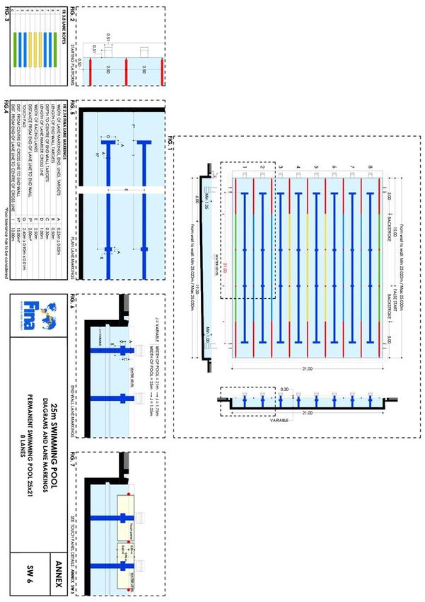
FACILITIES RULES 2017 – 2021

                     Each lane line shall end 2.0* metres from the end wall of the pool with a distinctive
                     cross line 1.0 metre long and of the same width as the lane line. Target lines shall be
                     placed on the end walls or on the touch panels, in the centre of each lane, of the same
                     width as the lane lines. *Pool length tolerances must be considered.

                     They shall extend without interruption from the deck edge (curb), to the floor of the
                     pool to a maximum of 3 metres. A cross line 0.5 metre long shall be placed 0.3 metre
                     below the water surface, measured to the centre point of the cross line.
                     For 50m and 25m pools constructed after 1 January 2006, cross lines 0.5 metre long
                     shall be placed at the 15 metre mark from each end of the pool. After October 2013
                     this shall be measured from the end wall to the centre point of the cross line.
                     See Swimming Diagrams SW 1, SW 6, SW 7
                     For swimming pools with bulkheads, lane markings shall be as shown on
                     Swimming Diagram SW 8

         FR 2.15      Bulkheads
         When a bulkhead serves as an end wall, it must extend the full width of the course and present a
         solid smooth, non-slippery stable vertical surface on which touch pads may be mounted extending
         not less than 0.8m below and 0.3m above the surface of the water, and must be free of hazardous
         openings above or below the waterline which may be penetrated by a swimmer’s hands, feet, toes
         or fingers. A bulkhead must be of a design that provides for the free movement of officials along its
         length without such movement creating any appreciable current or water turbulence.

FR 3     SWIMMING POOLS FOR OLYMPIC GAMES AND WORLD CHAMPIONSHIPS

         Length: 50.0 metres between the Automatic Officiating Equipment touch panels, except for the World
         Swimming Championships (25m), which shall be 25.0 metres between the Automatic Officiating
         Equipment touch panels at the starting end and the wall or touch panels at the turning end.

         FR 3.1      Dimensional Tolerances as in FR 2.2.1.

         FR 3.2      Width:

                     OLYMPIC GAMES
                     •   Permanent Swimming Pools: 25.00 meter
                     •   Temporary Swimming Pools: 25.00 meter

                     WORLD CHAMPIONSHIPS
                     •  Permanent Swimming Pools: 25.00 meter
                     •  Temporary Swimming Pools: 26.00 meter

         FR 3.3      Depth: 2 Metres (minimum); 3 metres recommended, when using the pool for multi
                     disciplines i.e. Artistic Swimming

         FR 3.4      Walls: as in FR 2.4.1.

Version 28.01.2020                                                                                           8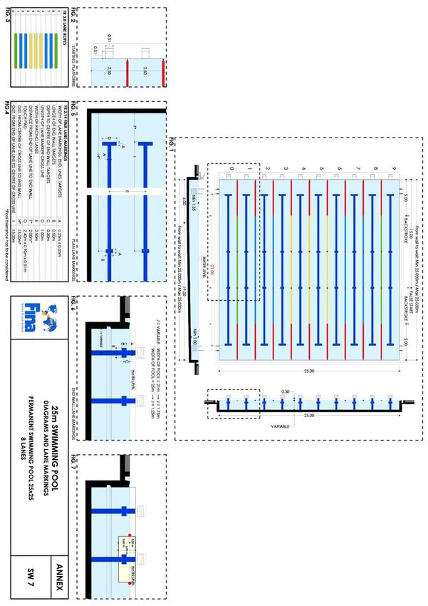
FACILITIES RULES 2017 – 2021

         FR 3.5      Pools for Olympic Games and World Championships must be equipped with flush
                     walls (consistently flat) at both ends.

         FR 3.6      Number of lanes:

                     •     8 lanes for OLYMPIC GAMES
                     •     10 lanes for WORLD CHAMPIONSHIPS

         FR 3.7      Lanes

                     FR 3.7.1 Olympic Games. Lanes shall be 2.5 metres wide with 2 spaces 2.5 metres
                     wide outside of lanes 1 and 8. There must be a lane rope separating these spaces from
                     lanes 1 and 8. See Diagram: SW 1

                     FR 3.7.2 World Championships. For permanent swimming pools, lanes from 1 to
                     8 shall be 2.5 metres wide and lanes 0 and 9 shall be 2.4 metres wide with 2 spaces
                     0.1 metres wide outside of lanes 0 and 9. There must be a lane rope separating these
                     spaces from lanes 0 and 9 for World Championships. See Diagram: SW 2, SW 4

                     For temporary swimming pools, lanes shall be 2.5 metres wide with 2 spaces 0.5
                     metres wide outside of lanes 0 and 9. There must be a lane rope a separating these
                     spaces from lanes 0 and 9. See Diagram: SW 3, SW 5

         FR 3.8      Lane Ropes: The main function of a lane rope is not only to separate swimming lanes,
         but to reduce the pool waves. A lane rope should have the properties to reduce the waves going
         through to the other side of rope or bouncing back into the swimming lane.

         In an 8 lane pool, lane ropes shall extend the full length of the course and components not
         contributing to its wave reduction function, such as tension spring and take‐up reel, shall measure
         less than 200mm each end of rope.

         Lane rope should be secured at each end wall to anchor brackets recessed into the end walls. If
         anchor placement is on pool deck, an extender, firm and non‐elastic, should be in place. The
         installed lane rope should stay in the pool water. The anchor, including extender, shall not extend
         more than 10mm into the pool. The anchor shall not influence the length of the lane rope by more
         than +‐ 10mm each end of rope.

         The anchor shall be positioned so that the wave reducing components at each end wall of the pool
         shall be 50% below the surface of the water. Anchors should be installed to withstand 20kN. Each
         lane rope will consist of wave reducing components placed end‐to‐end having a minimum diameter
         of 0, 15 metre. The design of discs and floats should be so that the floats, by themselves, do not
         influence the length of the lane rope. A float should be an integral part in between two discs. The
         lane rope length of the course shall have a negative buoyancy in such a way that at least one half
         to maximum two thirds of the height of the wave reducing components should be beneath the water
         surface.

         The take‐up reel of the lane rope should require a tool to lock tensioning into position and to prevent
         non‐ authorized tampering. The lane rope shall be equipped with a tension spring, absorbing
         sudden high point loads and a wire withstanding a tensile force of 12kN.

Version 28.01.2020                                                                                            9
FACILITIES RULES 2017 – 2021
In a swimming pool the colour of the lane ropes should be as follows:
• Two (2) GREEN ropes for lanes 1 and 8
• Four (4) BLUE ropes for lanes 2, 3, 6 and 7
• Three (3) YELLOW ropes for lanes 4 and 5
The components extending for a distance of 5.0 metres from each end of the pool shall be of RED
colour.
There shall not be more than one lane rope between each lane. The lane ropes shall be firmly
stretched and the tensions should be 1‐1,2kN. See Swimming Diagram SW 1, SW 2, SW 3, SW8
OLYMPIC GAMES
In an 8 (eight) lanes swimming pool the colour of the lane ropes should be as follows:
• Two (2) GREEN ropes for lanes 1 and 8
• Four (4) BLUE ropes for lanes 2, 3, 6 and 7
• Three (3) YELLOW ropes for lanes 4 and 5
WORLD CHAMPIONSHIPS
In a 10 (ten) lanes swimming pool the colour of the lane ropes should be as follows:
• Two (2) GREEN ropes for lanes 0 and 9
• Six (6) BLUE ropes for lanes 1, 2, 3, 6, 7 and 8
• Three (3) YELLOW ropes for lanes 4, 5
Version 28.01.2020 10FACILITIES RULES 2017 – 2021
FR 3.9 Starting Platforms: as in FR 2.7.
Except the surface area shall be at least 0.5 metres wide X 0.6 metres in length and covered with
non-slip material. False start control equipment must be installed.
FR 3.10 Numbering: as in FR 2.8.
FR 3.11 Backstroke turn indicators: as in FR 2.9
Flagged ropes must be 1.8 metres above the water surface. Flags must be fixed to the ropes
having the following dimensions: 0.20m metres on the rope forming a triangle measuring 0.40
metres on the sides. The distance between each flag must be 0.25metres. If the flags are printed
with or support / carry any signage this must be approved in advance by FINA
FR 3.12 Backstroke Ledge: as in FR 2.10
FR 3.13 False Start Rope: as in FR 2.11
FR 3.14 Water Temperature: as in FR 2.12
FR 3.15 Lighting: Light intensity over the whole pool shall not be less than 1500 lux.
FR 3.16 Lane Markings: as in FR 2.14. The distance between the centre points of each lane
shall be 2.5 metres
FR 3.17 If the swimming pool and the diving well are in the same area the minimum distance
separating the pools shall be 5.0 metres. For pools constructed from 1 January 2014 the minimum
distance separating the pool shall be a minimum of 8 metres however 10 metres is preferred
FR 4 AUTOMATIC OFFICIATING EQUIPMENT
FR 4.1 Automatic and Semi-Automatic Officiating Equipment records the elapsed time of each
swimmer and determines the relative place in a race. Judging and timing shall be to 2 decimal
places (1/100 of a second). Equipment that is installed shall not interfere with the swimmers' starts,
turns, or the function of the overflow system.
FR 4.2 The Equipment must:
FR 4.2.1 Be activated by the starter.
FR 4.2.2 Have no exposed wires on the pool deck, if possible.
FR 4.2.3 Be able to display all recorded information for each lane by place and by lane.
FR 4.2.4 Provide easy digital reading of a swimmer's time.
Version 28.01.2020 11FACILITIES RULES 2017 – 2021
FR 4.3 Starting devices
FR 4.3.1 The starter shall have a microphone for oral commands.
FR 4.3.2 If a pistol is used, it shall be used with a transducer.
FR 4.3.3 Both the microphone and the transducer shall be connected to
loudspeakers at each starting block where both the starter's commands and the starting
signal can be heard equally and simultaneously by each swimmer.
FR 4.4 Touch panels for Automatic Equipment
FR 4.4.1 The minimum measurement of the touch panels shall be 2.4 metres wide
and 0.9 metre high, and the thickness shall be 0.01m when the contact is closed (and
the time is stopped).
They shall extend 0.3 metre above and 0.6 metre below the surface of the water. The
equipment in each lane shall be connected independently, so it may be controlled
individually. The surface of the panels shall be of a bright colour and shall bear the line
markings approved for the end walls.
FR 4.4.2 Installation - The touch panels shall be installed in a fixed position in the
centre of the lanes. The panels may be portable, allowing the pool operator to remove
them when there are no competitors.
FR 4.4.3 Sensitivity - The sensitivity of the panels shall be such that they cannot be
activated by water turbulence, but will be activated by a light hand touch. The panels
shall be sensitive on the top edge.
FR 4.4.4 Markings - The markings on the panels shall conform with and superimpose
on the existing markings of the pool. The perimeter and edges of the panels shall be
defined by a 0.025 metre black border.
FR 4.4.5 Safety - The panels shall be safe from the possibility of electrical shock and
shall not have sharp edges.
FR 4.5 With Semi-Automatic Equipment, the finish shall be recorded by buttons pushed by
timekeepers at the finish touch of the swimmer.
FR 4.6 The following accessories are essential for a minimum installation of Automatic
Equipment:
FR 4.6.1 Printout of all information, which can be regenerated during a succeeding race.
FR 4.6.2 Spectator readout board.
Version 28.01.2020 12FACILITIES RULES 2017 – 2021
FR 4.6.3 Relay take-off judging to 1/100 of a second. Where overhead video
cameras are installed they may be reviewed as a supplement to the automatic system’s
judgement of relay take-off. For the differential in the relays take-off the manufacturer
of the device shall be consulted.
FR 4.6.4 Automatic lap counter.
FR 4.6.5 Readout of splits.
FR 4.6.6 Computer summaries.
FR 4.6.7 Correction of erroneous touch.
FR 4.6.8 Automatic rechargeable battery operation possibility.
FR 4.7 For Olympic Games and World Championships the following accessories are also
essential:
FR 4.7.1 The spectator electronic read-out board shall contain at least twelve (12)
lines of thirty-two (32) characters, each capable of displaying both letters and numbers.
Each character shall have a minimum height of 360 mm. Each line – matrix scoreboard
shall be able to scroll up or down, with blink function, and each full matrix scoreboard
shall be programmable, and capable of showing animation. The board must have a
minimum size of 7.5 m width by 4.5m height.
FR 4.7.2 There shall be an air-conditioned control centre, with dimensions of a least
6.0 metres x 3.0 metres, located between 3.0 metres and 5.0 metres from the finish
wall, with an unobstructed view of the finish wall at all times during the race. The referee
must have easy access to the control centre during the competition. At all other times
the control centre shall be able to be secured.
FR 4.7.3 Video timing
FR 4.8 Semi-Automatic Equipment may be used as a backup to the Automatic Officiating
Equipment at FINA or other major events if there are three buttons per lane, each operated by a
separate official (in which case other finish judges shall not be required). An inspector of turns may
operate one of the buttons.
DIAGRAMS FOR SWIMMING (Total 9)
FR 5 DIVING FACILITIES
FR 5.1 Springboard Diving
General requirements: Dimensions in metres for all diving facilities as detailed in Diving Diagram,
Annex 1.1 & Annex 1.2, shall be observed.
FR 5.1.1 The springboards shall be 4.88 metres long and 0.5 metre wide. At all
FINA Events, the type of springboard which must have a slip-resistant surface shall
be approved by FINA.
Version 28.01.2020 13FACILITIES RULES 2017 – 2021
FR 5.1.2 The springboards shall be provided with movable fulcrums easily
adjustable by the diver.
FR 5.1.3 For springboard diving facilities modified or constructed on concrete
platforms after 1 October 2013, the following shall be observed
FR 5.1.3.1 The vertical distance from the level of the platform, which
supports the fulcrum assembly, to the level of the top of the springboard,
shall be 0.35 metre.
FR 5.1.3.2 The distance from the front edge of the fulcrum assembly
(which is 0.741 metres in length) to the front edge of the supporting
platform, shall be a maximum of 0.44 metre.
FR 5.1.3.3 If the front edge of the platform projects past this point then
the fulcrum assembly and the rear hinge assembly must be moved
forward so as to provide for a maximum of 0.44 metres from the front edge
of the platform to the front of the fulcrum assembly.
FR 5.1.3.4 The concrete platform which supports the springboard
shall be aligned with the pool wall or project over the pool.
FR 5.1.4 The minimum distance recommended from the rear to the centre line of
the fulcrum shall be in accordance with the recommendation or specification of the
springboard manufacturer.
FR 5.1.5 The springboards shall be installed dead level at the leading edge when
the movable fulcrum is in all positions.
FR 5.1.6 The springboards should be placed on either one or both sides of the
platform. For Synchronised Diving, it is required that at least two springboards at the
same height shall be placed side by side and no objects should obstruct the visibility
in any part of the dive between the divers.
See Diving Diagram, Annex 2.1 & Annex 2.2
FR 5.1.7 The back and sides of 3m springboards shall be surrounded by handrails
with a minimum clearance of 1.0 metres between vertical pairs. The minimum height
shall be 1.0 metre, measured from the level of the springboard, and they shall be with
at least two horizontal crossbars placed outside the platform.
A solid transparent barrier is also permitted instead of a crossbar.
See Diagram: DV 1
Version 28.01.2020 14FACILITIES RULES 2017 – 2021
FR 5.2 Platform Diving
FR 5.2.1 Each platform shall be rigid and horizontal.
FR 5.2.2 The minimum dimensions of the platform shall be:
PLATFORM WIDTH LENGTH
0.6m to 1.0m 1.00m (2.90m preferred) 5.00m
2.6m to 3.0m 1.00m (2.00m preferred) 5.00m
5.0m 2.90m 6.00m
7.5m 2.00m 6.00m
10.0m 3.00m 6.00m
On 10m platforms, with a width of less than 3m,
only the handrails on each side for a distance of
at least 3.0m back from the front edge of the
platform may be shaped as detailed next (see
drawing).
It is recommended that an easily removable
section of handrail be included for general use,
which can be removed for synchronised diving.
See Diagram
FR 5.2.3 The preferred thickness of the front edge of the platform shall be 0.2 metre
but not exceeding 0.3 metre, and can be vertical or inclined at an angle not greater than
10 to the vertical inside the plummet line. The front edge is to be applied first and then
the top surface.
FR 5.2.4 The surface and the front edge of the platform shall be covered throughout
with a resilient slip-resistant surface. The two surfaces shall be covered separately in
order to achieve a clean 90° angle or as described in FR 5.2.3. The front surface is to
be applied first and then the top surface.
FR 5.2.5 The platforms shall be covered in a slip-resistant material that shall have
a tread pattern that provides sufficient traction in wet and dry conditions such that the
divers are prevented from slipping when performing dives in all directions. The
minimum thickness must be 6mm (- 0 / + 1mm) and the colour should give a contrast
to the surrounding décor. The material shall be easily cleaned to maintain the anti-
slip feature of the product. The installation of the slip-resistant platform covering shall
respect FINA Rule FR 5.2.4.
Version 28.01.2020 15FACILITIES RULES 2017 – 2021
FR 5.2.6 The front edge of the 10 metre platform shall project at least 1.50 metres,
the 7.5 metre, 5 metre and 2.6 – 3.0 metre platforms 1.25 metres, and the 0.6 – 1
metre platform 0.75 metre beyond the edge of the pool.
FR 5.2.7 Where a platform is directly underneath another platform the platform
above shall project a minimum of 0.75 metre (preferred 1.25 metres) beyond the
platform below.
FR 5.2.8 The back and sides of each platform (except 1.0 metre or lower platforms)
shall be surrounded by handrails up to 1m from the edge of the platform with a
minimum clearance of 1.0 metres between vertical pairs. The minimum height shall
be 1.0 metre and they shall be with at least two horizontal crossbars placed outside
the platform beginning 1.0 metre from the front edge of the platform.
A solid transparent barrier is also permitted instead of a crossbar.
FR 5.2.9 Each platform shall be accessible by suitable stairs (not ladders) as
required by the countries building regulations and or health and safety standards that
are applicable.
FR 5.2.10 It is preferable that a platform is not constructed directly under any other
platform however in circumstance where this cannot be avoided then you must refer
to Diving Diagram, Annex 1.1, 1.2, 2.1 & 2.2.
FR 5.2.11 Requirements for the supporting structure. For platforms and supporting
structure of the springboards the design load is p = 350 kiloponds (kilograms force)
per lineal metre.
In addition to the static requirements and for the comfort and safety of the user with
respect to the movement of the towers, the following limits shall be observed, with
respect to the platforms and springboard supports.
Fundamental frequency of platforms 10.0 Hz
TOLERANCES:
PLATFORM MINIMUM MAXIMUM
10m 10 Hz 20 Hz
7.5m, 5m, 3m and 1m 10 Hz 30 Hz
Fundamental frequency of tower 3.5 Hz
Total oscillation of total structure ± 2mm
The spatial deformation of the front edge of the
platforms as a result of Px = Py = Pz = 100 kiloponds
(kilograms force) shall be a maximum of 1 mm .
See Drawing
Version 28.01.2020 16FACILITIES RULES 2017 – 2021
These requirements can be met most adequately by a reinforced concrete structure.
Proof of the dynamic behavior is to be obtained together with the static calculations
for the whole structure.
FR 5.3 General Requirements
FR 5.3.1 For pools designed and constructed after 26 th September 2013 the
minimum dimensions in metres for diving facilities as detailed on the “Diving Facilities
Diagram” (Annex 1.2) shall prevail, using, as a basic measuring point of reference,
the plummet line, which is a vertical line extending through the centre of the front edge
of the springboard or platform. It is recommended that the preferred dimensions be
used for projects considered to have an important status.
FR 5.3.2 The dimensions C from plummet to adjacent plummet in the “FINA
Dimensions for Diving”, Annex 1.2 table apply to platforms with widths as detailed in
FR 5.2.2. If platform widths are increased then the dimensions B and C shall be
increased by half the additional widths.
FR 5.3.3 The height of the springboards and each platform above the water level
may vary by plus 0.05 metre and minus 0.00 metre from the heights prescribed in the
Rules.
FR 5.3.4 The end of 5, 3, and 1 metre platforms must not project beyond the ends
of the 3 and 1 metre springboards when they are adjacent to each other.
FR 5.3.5 In the area of full water depth, the bottom of the pool may rise up to 2%. In
the diving pool, the depth of water shall not be less than 1.8 metres at any point.
FR 5.3.6 In outdoor pools, best practice suggests that springboards and platforms
are recommended to face north in the northern hemisphere and south in the southern
hemisphere.
FR 5.3.7 The minimum illumination at a level of 1 metre above the water surface
shall not be less than 600 lux.
FR 5.3.8 Sources of natural and artificial illumination shall be provided with controls
to prevent glare.
FR 5.3.9 The water temperature shall be not less than 26 Celsius.
FR 5.3.10 Pool walls shall be vertical and form 90 degree right angles to the surface
of the water. They shall be constructed of solid material, with a non‐slip surface.
The admissible tolerance in walls verticality will be ±0.3 degrees.
Rest ledges along the pool walls are permitted; they must be not less than 1.2
metres below the water surface, and may be 0.1 metre to 0.15 metre wide. Only
internal rest ledges are permitted.
Version 28.01.2020 17FACILITIES RULES 2017 – 2021
FR 5.3.11 Mechanical surface agitation shall be installed under the diving facilities
to aid the divers in their visual perception of the surface of the water. In pools equipped
with an underwater bubble machine, the machine shall only be used for the purpose
if it creates sufficient water agitation when working with a very low pressure; otherwise
a horizontal water sprinkler system shall only be used.
FR 5.3.12 For Diving Pools that will also be used for swimming.
Lane markings for Diving pools shall be of a dark contrasting colour, placed on the
floor of the pool in the centre of each lane.
Width: minimum 0.2 metre, maximum 0.3 metre.
Length: 21.0 metres for 25 metre long pools.
Each lane line shall end 2.0 metres from the end wall of the pool with a distinctive
cross line 1.0 metre long and of the same width as the lane line. Target line shall be
placed on the end of the walls or on the touch panels, in the centre of each lane, of
the same width as the lane lines. A cross line 0.5 metre long shall be placed 0.3 metre
below the water surface, measured to the centre point of the cross line. They shall
extend without interruption from the deck edge (curb) to the floor or to a maximum of
3 metres.
FR 5.3.13 Individual diving
FR 5.3.13.1 The judges will be placed side by side in a line on each side
of the springboard / platform by the Referee.
FR 5.3.13.2 When seven (7) / five (5) judges are used, four (4) / three
(3) judges will be on the side closest to the competition.
Note: The Referee may decide to place four (4) / three (3) judges farthest
from the competition depending of the local situation in the pool.
FR 5.3.13.3 No judge shall be seated behind the front edge of the
springboard or platform.
FR 5.3.13.4 The numbering of the judge chairs will be clockwise when
facing the springboard / platform.
FR 5.3.13.5 In the 1 metre springboard competitions, chairs suitable for
use on poolside shall be used.
FR 5.3.13.6 In the 3 metre springboard competitions, the judges shall
be seated at a height of not lower than two (2) metres above the water
level.
Version 28.01.2020 18FACILITIES RULES 2017 – 2021
FR 5.3.13.7 In the 10 metre platform competitions, the chairs from the
3m springboard competitions can be used but if at all possible, the judges
shall be seated at an even higher level.
FR 5.3.13.8 To assist the judges in the 3 metre springboard and 10
metre platform competitions, the judge chairs must be positioned as far
back from the edge of the pool as is practical.
FR 5.3.14 Synchronised diving
FR 5.3.14.1 Three (3) / two (2) execution judges will be placed on either
side of the springboard / platform by the Referee.
FR 5.3.14.2 The numbering of the execution judge chairs will be
clockwise when facing the springboard / platform, namely E 1, E 2 and E
3 (or E 1, E 2) on the left side and E 4, E 5 and E 6 (or E 3, E 4) on the
right side.
FR 5.3.14.3 In between the execution judges on either side of the pool,
the synchronised judges will be placed in a line.
FR 5.3.14.4 Three (3) synchronised judges will be on the side closest
to the springboard / platform competition, and the other two (2)
synchronised judges on the opposite side.
FR 5.3.14.5 The numbering of the synchronised judge chairs will start
on the left-hand side on the pool with the lowest chair being S 1, and the
highest chair on the right-hand side of the pool being S 5.
FR 5.3.14.6 In the synchronised competitions, the synchronised judges
closest to the pool edge, shall be seated at a height of not lower than 2.0
metres above the water level.
FR 5.3.14.7 The subsequent heights for the remaining synchronised
judges (or additional execution judge) must increase no less than 0.5
metre per seat.
FR 5.3.14.8 There shall be no interference or movement in front of the
judge chairs.
FR 5.3.14.9 The above recommendations are shown in Diving
Diagram, DV 3 and DV 4.
Version 28.01.2020 19FACILITIES RULES 2017 – 2021
FR 5.3.15 Dry Land Training Facilities
General Requirements: Dimensions in metres for Dry Land Training Facilities as
detailed in Diving Dry Land Training, Diagram DV 5 and DV 6 and Diving Dry Land
Recommended Equipment, Diagram DV 7 and DV 8.
FR 5.3.15.1 For the safety, practise and development of divers and
competitions, it is strongly recommended that the guidelines presented
below be incorporated into the facility and placed adjacent to the
competitive diving area /facilities.
FR 5.3.15.2 When minimum dimensions are used in B and C a vertical
mat or other protective surface should be attached to the appropriate
forward and side walls.
FR 5.4 Electronic Officiating Equipment
FR 5.4.1 Electronic Officiating equipment records the judges awards for each
diver and determines the final score for each dive as required by Rule D 7
FR 5.4.2 Preferred Equipment must be able to;
FR 5.4.2.1 Record judges awards by whole and half points
FR 5.4.2.2 Be able to display all recorded and calculated information
for each diver both before and after each dive
FR 5.4.2.3 Be able to display the scores for all divers before and after
each dive
FR 5.4.2.4 Be able to display the rank order and scores for all divers
after each round of dives
FR 5.4.2.5 The equipment must provide each judge with an electronic
judging device that will permit each judge to enter their award and to see
their award on a window on the device. After the referee has accepted the
judges awards, all awards shall be displayed on each electronic judging
device
FR 5.4.2.6 Judges analysis is to be provided at the conclusion of each
event or series
FR 5.4.2.7 The referee must be provided with a monitor on which he/
she will be able to view the awards of all the judges prior to the awards
then being displayed on the score board
Version 28.01.2020 20FACILITIES RULES 2017 – 2021
FR 5.4.2.8 There is a requirement for a print out of the following information;
1. The draw for the diving order
2. A start list for each session or event
3. A ranking of dives at the end of each round
4. A ranking of dives at the end of each event
5. Judges awards and scores for each diver
at the end of each session and event
FR 6 DIVING FACILITIES FOR OLYMPIC GAMES AND WORLD CHAMPIONSHIPS
FR 6.1 General requirements: Dimensions in Metres for Diving Facilities as detailed in
Diving Diagram, Annex 1.1 & Annex 1.2 and ‘Field of Play for Olympic Games and World
Championships: Diving Diagram, Annex 2.1 & Annex 2.2.
FR 6.1.1 For Olympic Games and World Championships FR 5 in total shall apply;
however, the light intensity at the level of 1 metre above the water surface shall not
be less than 1500 lux.
FR 6.2 With regard to dimensions for diving facilities a combination of preferred and minimum
measurements found in the “FINA Dimensions for Diving Facilities, Annex 1.1 & Annex 1.2 table
may be used. However, measurements less than minimum are not acceptable and may not be
used. If the swimming pool and diving well are in the same area, the minimum distance separating
the pools shall be of 8 metres, however 10 metres is preferred (see FR 3.16).
FR 6.2.1 The vertical height from the plummet of the diving board and or
springboard at rest to the water surface at rest and before water sprays or bubbles
are set in motion shall be specified in the Diving Facilities Dimensions table. These
measurements should be certified by a surveyor or other qualified officials, appointed
or approved by the member of the country in which the pool is situated.
FR 6.3 Line markings for the diving well will consist of 3 lines running the width of the diving
well 90 degree angle to the diver facing forward on the springboard or platform. These lines shall
be as follows:
Width: minimum 0.2 metre, maximum 0.3 metres
Length: 21.0 metre for 25 metre wide diving well
The distance between the centre points of each lane shall be 2.5 metres
The centre of the first line shall be directly under the plummet of the 3 metre
springboard. See Diving Diagram, Annex 2.1 & Annex 2.2
FR 6.4 The host facility must provide a trampoline with spotting equipment and a hot tub. It
is preferred that there be two trampolines and a dry land area with a springboard and a platform
take-off into foam landing pits as detailed in Annex 3.1.
DIAGRAMS FOR DIVING (Total 8)
Version 28.01.2020 21FACILITIES RULES 2017 – 2021
FR 7 POOLS FOR WATER POLO
FR 7.1 General requirements: Water Polo Dimensions and Equipment as detailed in Field
of Play for Olympic Games and World Championships.
See Water Polo Diagram, Annex 5
FR 7.2 Field of Play.
The overall Field of Play will be 30.60m x 20.00m for men and 25.60m x 20.00m for
women.
The distance between respective goal lines shall be 30.00 metres for games played
by men and 25.00 metres for games played by women.
The anchor point at the edge of the Field of Play shall be placed 30cm behind the
front of the goal line. The width of the Field of Play shall be 20.00 metres.
The depth of the water shall be consistently not less than 2.00 metres
FR 7.3 The water temperature shall not be less than 26 plus 1 minus 1 Centigrade.
FR 7.4 The light intensity shall not be less than 600 lux.
FR 7.5 Exception from FR 7.2 may be allowed on the discretion of the federation controlling
the match.
FR 7.6 The game secretariat shall be placed at a table behind the referees and at the same
height
FR 7.7 Ceiling height for Indoor Pools
Minimum Ceiling height is not required.
FR 8 WATER POLO POOLS FOR OLYMPIC GAMES AND WORLD CHAMPIONSHIPS
See Water Polo Diagram, Annex 5
FR 8.1 Exceptions from the requirements in FR 7.2 are not allowed.
FR 8.2 The water temperature shall be as in FR 7.3.
FR 8.3 The light intensity shall not be less than 1500 lux.
Version 28.01.2020 22FACILITIES RULES 2017 – 2021
FR 8.4 In Olympic Games, World Championships and FINA events only water with less than 3
gr/litre of salt shall be used.
FR 8.5 Ceiling height for Indoor Pools
In indoor swimming pools the minimum height of the Field of Play shall be not less than
7.00 meter.
FR 9 EQUIPMENT FOR WATER POLO POOLS
FR 9.1 Distinctive marks shall be provided on both sides of the field of play to denote the goal
lines, lines 2.0 metres and 6.0 metres from that line and half the distance between the goal lines.
These markings shall be clearly visible throughout the game.
The white marker shall be measured from the anchor point and will be 0.3 metres to line up with
the front of the edge of the goal line. This shall be consistent at both ends of the field.
The 2 metre red marker shall be measured from the front end of the goal line extending into the
field of play. This shall be consistent at both ends of the field of play.
The yellow marker shall then extend 4 metre from the 2 metre marker into the field of play. There
will be a red marker placed 5 metre from the front end of the goal line. This shall be consistent at
both ends of the field of play.
The middle section of the field of play will be green and should be 18 metre for the men’s game
and 13 metre for the women’s game. There will be a white marker placed in the middle of the
green area to denote the centre of the field.
The exclusion zones shall be placed in the two corners on the opposite side of the pool to the
official table. They shall be 2 metre in length and shall extend along the goal line.
FR 9.2 Platforms must be provided on both sides of the field of play, which shall be 1 metre
in width and 70 cm in height above the water level. These platforms enable the referees to have
free way from end to end of the field of play. Sufficient space shall also be provided at the goal
lines for the Goal Judges. The platforms must be colour coded to meet the specification as shown
in the diagram of the field of play. See Water Polo Diagram WP 2
FR 9.3 Goals: The goal posts and crossbar must be of wood, metal or synthetic (plastic) with
rectangular sections of 80,0 millimetres, square with the goal line and painted white.
The goal posts must be fixed, rigid and perpendicular at each end of the playing space, equal
distances from the sides and at least 0.3 metre in front of the ends of the field of play or of any
obstruction. Any standing or resting place for the goalkeeper other than the floor of the pool is not
permitted.
FR 9.4 The inner sides of the goal posts must be 3.0 metre apart. The underside of the cross
bar must be 0.9 metre above the water surface.
FR 9.5 The underside of the crossbar must be 0.9 metre above the water surface when the
water is 1.5 metre or more in depth, and 2.4 metre above the bottom of the pool when the depth of
the water is less than 1.5 metre.
FR 9.6 The rectangular excluded players’ re-entry area shall have the following dimensions: 2.0
metres by 1.08 metre.
Version 28.01.2020 23FACILITIES RULES 2017 – 2021
FR 9.7 Limp nets must be attached to the goal fixtures to enclose the entire pool space
securely fastened to the goal posts and crossbar, allowing not less than 0.3m of clear space
behind the goal line everywhere within the goal area.
FR 9.8 Automatic Officiating Equipment
DIAGRAMS FOR WATER POLO (TOTAL 2)
FR 10 POOLS FOR ARTISTIC SWIMMING
FR 10.1 General requirements: Field of Play for Artistic Swimming in Olympic Games and
World Championships as detailed in: Artistic Swimming Diagram, Annex 6.
FR 10.1.1 For the figure section of competition two areas each 10.0 metres long by
3.0 metres wide are to be provided. Each area is to be close to a wall of the pool with
the 10.0 metre long side parallel to and not greater than 1.5 metres from the pool wall.
One of these areas is to be of 3.0 metres minimum depth and the other area is to be
of 2.5 metres minimum depth.
FR 10.2 For the routine section of competition a minimum area of 12 meters by 25 meters is
required, within an area of which 12 meters by 12 meters must have a minimum depth of 3.0 meters.
The depth of the remaining area shall be 2.0 meters minimum.
FR 10.2.1 Delimit in width and length the field of play in the Solo and the Duet with
two lanes (maximum width 16m length 25m).
For the Solo and Duet competition, the field of play may be delimited in width and
length.
FR 10.3 Where the water depth is more than 2.0 metres, the depth at the pool wall may be 2.0
metres and then sloped down to reach the general depth at 1.2 metres maximum from the pool
wall.
FR 10.4 The areas for figure competition in FR 10.1 can occupy the same area of the pool as
that used for routine competition.
FR 10.5 If there are no lane markings as described in FR 2.13, the floor of the pool must be
marked with contrasting lines in one direction, following the length of the pool.
FR 10.6 The water must be of sufficient clarity for the bottom of the pool to be visible.
FR 10.7 The water temperature shall not be less than 27° plus 1 minus 1 Centigrade.
Version 28.01.2020 24FACILITIES RULES 2017 – 2021
FR 11 POOLS FOR ARTISTIC SWIMMING IN OLYMPIC GAMES AND WORLD CHAMPIONSHIPS
FR 11.1 The Field of Play for Artistic Swimming in Olympic Games and World Championships
as detailed in: Artistic Swimming Diagram, Annex 6.
FR 11.1.1 For the routine section of competition at Olympic Games and World
Championships a minimum area of 12.0 metres by 30.0 metres is required, within
which an area of 12.0 metres by 12.0 metres must have a minimum depth of 3.0
metres. The depth of the remaining area shall be 2.5 metres minimum. The sloped
area from 3.0 metres depth to 2.5 metres depth should be over a minimum distance
of 8.0 metres.
FR 11.2 The water temperature shall be as in FR 10.7.
FR 11.3 The light intensity shall not be less than 1500 lux.
FR 11.4 Automatic officiating equipment, as listed in FR 12 shall be available.
FR 11.5 Sound equipment and presentation standards as listed in FR 13 shall be available.
FR 11.6 Starting platform is recommended 0.7metres in height but not less than 0.5 metres.
See Synchro Diagram, Annex 6
FR 11.7 Judges Platform must have tables and chairs and be of a minimum height of 0.6
metres. See Synchro Diagram, Annex 6
FR 12 AUTOMATIC OFFICIATING EQUIPMENT
The minimum installation consists of:
FR 12.1 same number of score recorder units as judges (figure: 5 up to 28; routine 5 up to 15)
FR 12.2 the results may only be transferred after confirmation by the referee or appointed official
FR 12.3 result unit (computer) with result recording and backup system. Only FINA approved
programmes and systems are allowed.
FR 12.4 print out system for all recorded information, start lists and result lists;
FR 12.5 A judge’s evaluation system based on the recorded results (FR 12.3). Only FINA
TSSC approved programmes and system are allowed.
FR 12.6 scoreboard control unit with a scoreboard; of a minimum of 10 lines containing 32
digits (or scoreboard as described in Rule FR 4.7.1). The scoreboard must be able to display all
recorded information and the running time;
FR 12.7 for each judge flash cards in case of failure of the electronic system.
Version 28.01.2020 25FACILITIES RULES 2017 – 2021
FR 13 SOUND EQUIPMENT AND PRESENTATION STANDARDS
The sound equipment should include, at minimum:
FR 13.1 Amplifier-mixer system
Mixer should have at least 16 inputs and 6 outputs (LR (Left-Right channels) PA, LR Speaker
system on the field of competition, 2 outputs Spare/or for Broadcasting). Amplifiers should be
suitable for used speakers.
FR 13.2 A sound reproduction system
FR 13.2.1 High quality microphones and microphone stations for announcements
and ceremonies.
FR 13.2.2 High quality air speakers (AS) of size, number and placement to obtain
uniform clear sound to the field of competition area. And should be able to produce
105 db SPL (sound pressure level) A without distortion. The maximum SPL shall not
exceed 125 dB SPL A. Speakers frequency response should be at least 40Hz-16kHz
FR 13.2.3 High quality air speakers (AS) of size, number and placement to obtain
uniform clear sound to the start podium of competition area. And should be able to
produce 105 db SPL A without distortion. The maximum SPL shall not exceed 125 dB
SPL A. Speakers frequency response should be at least 40Hz-16kHz
FR 13.2.4 All air speaker (AS) in the field of competition should be «passive»
(without built-in amplifier) to avoid risk of electrical shock.
FR 13.2.5 UWS (Under Water Speaker) for clear and uniform underwater sound
above. UWS should be able to produce 98dB A without distortion. The maximum SPL
shall not exceed 110 dB SPL A. UWS frequency response should be at least 200Hz-
10kHz. Isolation and impedance matching transformer systems for the UW speakers.
FR 13.2.6 DSP (Digital Sound Processor) to make amplitude frequency
characteristic and delay corrections in between AS and UWS. DSP should have at
least 2 inputs and independent 6 outputs (or 3 Stereo independent outputs). Each
output should have HPF (High Pass Filter), LPF (Low Pass Filter), GEQ (Graphic
equalizer) and/or Parametric equalizer, compressor/limiter, Delay (minimum 5
seconds)
FR 13.3 PA (Public Address) System (Sound reproducing system for spectators)
FR 13.3.1 The sound system shall be capable to cover spectators seats at least
with 110 dB A with deviations in overall direct sound levels across the spectator
seating area not exceeding +/- 3 dB A. The maximum SPL shall not exceed 125 dB
SPL A.
Version 28.01.2020 26FACILITIES RULES 2017 – 2021
FR13.3.2 STI PA (speech transmission index for PA systems) should be in 0,5-
1.0 STI
FR13.3.3 The PA system shall provide enough headroom to compensate for the
atmospheric loss of high frequencies.
FR13.3.4 The PA system should have a minimal impact to the field of competition
to avoid sound delay problems.
FR 13.4 Sound volume (decibel) meter for monitoring music sound levels both above and
under water.
FR 13.5 Patch cords for interconnecting equipment properly, speaker extension lines
adequate for placing speakers for optimal sound distribution.
FR 13.6 Fusing systems as needed to protect speakers and other equipment.
FR 13.7 Grounding lines to ensure safe grounding of all equipment.
FR 13.8 Safety materials to minimize potential of injury to person or equipment from stepping
on or tripping over electrical or speaker lines.
FR 13.9 A stopwatch.
FR 13.10 Tools and meters as needed for initial special hookups and emergency repairs.
FR 13.11 Systems for communication between officials and sound desk.
FR 13.12 A system for monitoring and recording underwater sound continuously.
DIAGRAM FOR ARTISTIC SWIMMING (Total 1)
FR 14 HIGH DIVING FACILITIES RULES
General requirements and definitions:
High Diving can be performed from artificial towers, platforms on existing buildings or platforms on
natural rocks (cliffs) into open water (sea, lake, river) or in temporary or permanent artificial pools.
Permanent artificial pools are preferable square, temporary artificial pools are normally round.
Dimensions in metres for all high diving facilities as detailed in High Diving Facilities Diagram, HD
1 and HD 2, shall be observed. The HD 1, HD 2, HD 3 and HD 4 are established by the FINA Facilities
Committee in cooperation with the FINA Technical High Diving Committee and approved by the FINA
Bureau.
Version 28.01.2020 27FACILITIES RULES 2017 – 2021
In special surroundings the dimensions and requirements can be adjusted to the local situation upon
recommendation by the FINA Facilities Committee and the FINA THDC and approved by the FINA
Bureau.
Security: The dimensions of these facilities are only for the use of expert athletes and they are not
suitable for public use. It is required by the local organising committees and local authorities to provide
security guards and lockable structures or gates to prevent any unauthorised persons to climb the
diving towers.
FR 14.1 Platform High Diving
FR 14.1.1 Each platform shall be rigid and horizontal.
FR 14.1.2 The preferred thickness of the front edge of the platform shall not
exceeding 0.16 metre and can be vertical or inclined at an angle not greater than
10° to the vertical inside the plummet line.
FR 14.1.3 The platforms shall be covered with slip-resistant material that shall
have a tread pattern that provides sufficient traction in wet and dry conditions such
that the divers are prevented from slipping when performing dives in all directions.
FR 14.1.4 The back and sides of each platform shall be surrounded by handrails
up to 1m from the edge of the platform with a minimum clearance of 1.8 metres
between vertical pairs. The minimum height shall be 1.0 metre and they shall be
with at least two horizontal crossbars placed outside the platform beginning 1.00
metre from the front edge of the platform.
FR 14.1.5 Each platform shall be accessible by suitable slip-resistant stairs (not
ladders) as required by the country’s building regulations and or health and safety
standards that are applicable.
FR 14.1.6 It is preferable that a platform is not constructed directly under any
other platform however in circumstances where this cannot be avoided (example:
artificial pools) then the dimensions in High Diving Diagram, HD 2 must be
observed.
FR 14.1.7 The platform shall be a concrete, steel or other rigid material
construction as approved by FINA. The longitude and latitude
movement/oscillation allowance for the entire 27 metres high tower structure shall
be 2.7 cm (1/1000 from 27m). The maximum wind speed for the tower oscillation
stability is 54km/hour (banners will affect the stability). The downward flex at the
diving end of the platform shall not exceed 2-3mm and approved by the local
authority of the area.
FR 14.2 General Requirements
FR 14.2.1 For High Diving platforms designed and constructed after 31t
December 2017 the minimum dimensions in metres for high diving facilities as
detailed on the “High Diving Facilities Diagram” (HD 1 and HD 2) shall prevail,
using, as a basic measuring point of reference, the plummet line, which is a
vertical line extending through the centre of the front edge of the platforms.
FR 14.2.2 The platforms shall face north in the northern hemisphere and south in
the southern hemisphere where possible.
Version 28.01.2020 28You can also read