Weather protection grilles - ALAS - Ferdinand Schad KG Steigstraße 25-27 D-78600 Kolbingen - Schako
←
→
Page content transcription
If your browser does not render page correctly, please read the page content below
Weather protection grilles
                 ALAS

             Ferdinand Schad KG
              Steigstraße 25-27
              D-78600 Kolbingen
       Telephone +49 (0) 74 63 - 980 - 0
         Fax +49 (0) 74 63 - 980 - 200
               info@schako.de
                 schako.com
Weather Protection Grille ALAS
Contents
Description ........................................................................................................................................ 3
   Construction .............................................................................................................................................................................. 3
   Model ......................................................................................................................................................................................... 3
   Accessories ................................................................................................................................................................................ 3
Models and dimensions ......................................................................................................................... 4
   Dimensions ................................................................................................................................................................................ 4
   Dimensions of accessories ........................................................................................................................................................ 5
Technical data .................................................................................................................................... 9
   Pressure loss and noise level ..................................................................................................................................................... 9
   Free cross section in m² ............................................................................................................................................................. 9
   Connection diagram ................................................................................................................................................................. 10
Legend ........................................................................................................................................... 10
Specification texts .............................................................................................................................. 10

                                                                                             08/01 - 2                                                               Version: 05.03.2021

Construction subject to change.                                                                                                                                       No return possible!
Weather Protection Grille ALAS
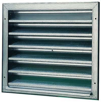
Description Construction
External air intake or return air grille with fixed, rain-repellent Blades
blades and back-fitted wire mesh grid. Mounting holes drilled as - Galvanised sheet steel
standard. - Natural aluminium
On request, all designs with mounting frames made of angular
- Natural colour anodised aluminium (E6/EV1)
30/30/3 steel are primed.
- Copper
ALAS with self-regulating heating strip Wire mesh grille
A better way of preventing ice formation is the installation of a - Galvanised steel
self-regulating heating strip. It is a heating strip that adapts the - Stainless steel 1.4301 (V2A)
heating output to the environment at any position of the grille. Frame
Available in any length, rated capacity max. 36 W/m. It can be
- Galvanised sheet steel
used up to -8 °C and 80% of relative humidity.
- Natural aluminium
ALAS with self-regulating "top" heating strip - Natural colour anodised aluminium (E6/EV1)
A better way of preventing ice formation is the installation of a - Copper
self-regulating heating strip. It is a heating strip that adapts the
heating output to the environment at any position of the grille. Model
Available in any length, rated capacity max. 64 W/m. It can be
used up to -15 °C and 80% of relative humidity. ALAS - Sheet steel design
ALAS-Alu - Aluminium design
Self-regulating heating strip ALAS-Cu - Copper design
The heating unit consists of semi-conductive, cross linked plas-
tic with two stranded copper conductors. As soon as ice is Accessories
formed, a current will flow through the heating element and gen-
erate heat. As soon as parts of the heating strip have defrosted Installation frame
and dried, the temperature rises on these parts and the resist- - Angular steel primed and perforated (unperforated if pre-
ance increases. This will minimise the current flow and the heat- ordered)
ing output. Heating strip
- plastic
- It can be used up to-8 °C and 80% of relative humidity.
"Top" heating strip
- plastic
- It can be used up to-15 °C and 80% of relative humidity.
Attention!
We would like to point out that for cleaning stainless steel mod-
els, only suitable cleaning materials may be used!
08/01 - 3 Version: 05.03.2021
Construction subject to change. No return possible!Weather Protection Grille ALAS
Models and dimensions Installation arrangement for sectioned design
at height > 1995
Dimensions
Mounting height (EMH)
For a height of > 1995 two standard surrounding air suction
grilles must be installed, one on top the other.
Available sizes Detail X
B B1 B2 H H1 H2 ALAS / ALAS-Cu Installation height (EMH):
400 475 389 345 420 338 "EMH=(H1xa)-(2x45)+15"
a = Number of grilles
600 675 589 510 585 503
800 875 789 675 750 668 for widths > 2000
1000 1075 989 840 915 833
1200 1275 11891005 1080 998
1400 1475 13891170 1245 1163
1600 1675 15891335 1410 1328
1800 1875 17891500 1575 1493
ALAS-Alu
2000 2075 19891665 1740 1658
1830 1905 1823
1995 2070 1988
Mounting width (EMB)
All combined widths and heights available!
1.) from height or width > 1600, 3 fixing holes per
side
2.) additional holes for widths > 900
For a width of > 2000 two standard surrounding air suction
grilles must be installed next to each other.
Installation width (EMB):
"EMB=(B1xa)-(2x45)+15“
a = Number of grilles
08/01 - 4 Version: 05.03.2021
Construction subject to change. No return possible!Weather Protection Grille ALAS
Position of fixing holes for band design
The illustration shows the grilles
as continuous run. Any number of
grilles can be installed next to each
other. Expansion joints have to be
allowed when fixing air suction
grilles on site.
On request, a mounting frame
made of angular steel 30/30/3 can
be delivered primed (at an extra
charge).
Mounting width (EMB) 1.) from a height or width > 1600, 3 fix-
ing holes per side
2.) additional holes for widths > 900
Dimensions of accessories
Mounting frame (-ER) Mounting frame for band design
Wall anchor
Wall anchor Mounting width (EMB)
Installation in front of the wall Installation in wall (mortar)
ALAS / ALAS-Cu ALAS-Alu ALAS / ALAS-Cu ALAS-Alu
Number of wall anchors for mounting frame
Height: H < 1000 = 2 wall anchors per side If the mounting frame is shipped beforehand, it will be delivered
unperforated.
1000 < H < 2000 = 3 wall anchors per side
A mounting frame in sectioned design must be screwed togeth-
er on site.
Width: B < 800 = without wall anchors
800 < B < 1000 = 2 wall anchors per side
1000 < B < 2000 = 3 wall anchors per side
08/01 - 5 Version: 05.03.2021
Construction subject to change. No return possible!Weather Protection Grille ALAS
Mounting detail ALAS with mounting frame Fixing lugs
Height one-piece Sectioned height (not removable from the outside)
Mounting height (EMH) + +10
Mounting height (EMH)
Sectioning of fixing lug
Height:
H < 800 a=100 2 fixing lugs per side
800 < H < 1100 a=140 2 fixing lugs per side
1100 < H < 1800 a=230 2 fixing lugs per side
1800 < H < 2000 a=230 3 fixing lugs per side
Wall Wall Width:
anchor anchor B < 900 b= ---- no fixing lug
900 < B < 1200 b=140 2 fixing lugs per side
1200 < B < 1800 b=230 2 fixing lugs per side
Sectioned width 1800 < B < 2000 b=230 3 fixing lugs per side
Separate fixing lugs
Wall
anchor
Sectioned width
Mounting width +10 Mounting detail fixing lug
Mounting width (EMB) to be screwed on-site riveted
Wall
anchor
08/01 - 6 Version: 05.03.2021
Construction subject to change. No return possible!Weather Protection Grille ALAS
ALAS with heating strip Technical details regarding the heating strip
Structure
1. 1.2 mm2 multi-strand copper conductor
2. Self-regulating, semi-conductive heating element
3. 0.7 mm electrical insulation made of modified polyolefin
4. Protection mesh made of galvanised copper leads
5. Outer casing made of modified polyolefin
Thermal safety class 0 according to VDE 0721 Part 2 E § 10
Technical data
Nominal voltage 230 V
Rated power
- Ice-water: at 0°C 36W/m
- Air: at 0°C 18 W/m
Connection max. resistance of protective mesh 0.0152 Ω/m
fittings max. permitted surrounding temperature
- switched on + 65 °C
- switched off + 85 °C
Per m² approx. 10 m of heating strip
Note
Protective measures for ALAS with heating strip
- The heating strip protective mesh must be connected to a
1. Protection against too high contact voltage: residual current protective conductor potential.
circuit breaker, nominal fault current 30 mA (according to - Provide FI residual current protective device
VDE 0100/5.73 § 13)
When used on metal, it must be included in the protective
2. Protection against atmospheric overvoltage: -
measures.
(according to VDE 0100/5.73 § 18 and the "General Light-
Protective measures and protection from contact have to be
ning Protection Regulations", ABB, Ed. 68 § 8) -
ensured during installation.
a) with surge arresters according to VDE 0675/5.72
- End of heating strip not heated connection spigot fitting
b) It is also advisable to connect the heating elements via a
- The heating strips are fitted during manufacture.
plug-and-socket device. During the season in which at-
mospheric disturbances (e.g. thunderstorms) occur,
disconnect the system from the power. Hang the plug to-
gether with all moving connections at a distance of min.
2 m from the power supply socket.
Connecting the heating strip
a) The electrical connection must be performed by a qualified
electrician taking all protective measures into consideration!
b) The following rules and regulations must be observed:
- VDE directives
- Regulations of the local power supply company
08/01 - 7 Version: 05.03.2021
Construction subject to change. No return possible!Weather Protection Grille ALAS
ALAS with "top" heating strip Technical details regarding the "top" heating strip
Structure
1. 1.4 mm2 multi-strand copper conductor
2. Self-regulating, semi-conductive heating element
3. Insulation made of fluoro polymer
4. Protection mesh made of galvanised copper leads
5. Outer casing made of fluoro polymer
Temperature classification T4 in accordance with European
standard EN 50014.
Technical data
Nominal voltage 230 V
Rated power
- Air: at 10°C 64W/m
max. resistance of protective mesh 0.01 Ω/m
Connection
fittings max. temperature of use (permanently switched
+ 110 °C
on)
Per m² approx. 10 m of heating strip Note
- The heating strip protective mesh must be connected to a
Protective measures for ALAS with "top" heating strip protective conductor potential.
1. Protection against too high contact voltage: residual current - Provide FI residual current protective device
circuit breaker, nominal fault current 30 mA (according to When used on metal, it must be included in the protective
-
VDE 0100/5.73 § 13) measures.
2. Protection against atmospheric overvoltage: Protective measures and protection from contact have to be
-
(according to VDE 0100/5.73 § 18 and the "General Light- ensured during installation.
ning Protection Regulations", ABB, Ed. 68 § 8) - The heating strips are fitted during manufacture.
a) with surge arresters according to VDE 0675/5.72
b) It is also advisable to connect the heating elements via a
plug-and-socket device. During the season in which at-
mospheric disturbances (e.g. thunderstorms) occur,
disconnect the system from the power. Hang the plug to-
gether with all moving connections at a distance of min.
2 m from the power supply socket.
Connecting the heating strip
a) The electrical connection must be performed by a qualified
electrician taking all protective measures into consideration!
b) The following rules and regulations must be observed:
- VDE directives
- Regulations of the local power supply company
08/01 - 8 Version: 05.03.2021
Construction subject to change. No return possible!Weather Protection Grille ALAS
Technical data
Pressure loss and noise level
ALAS / ALAS-Cu / ALAS-Alu Area correction
F (m²) 0,5 1 1,5 2 2,5 3 4
KF [dB(A)] -3 0 +2 +3 +4 +5 +6
Correction factor with insect protection wire fabric (MW=1.45
mm, D=0.5 mm) relative to 1 m²
vstirn (m/s) 0,5 1,0 1,5 2,0 2,5 3,0
KF (dB(A)) +4 +6 +8 + 10 + 12 + 14
KF (Pa) +8 + 10 + 14 + 18 + 22 + 28
intake-
operated
pressure-
operated
Free cross-section in m²
B
400 600 800 1000 1200 1400 1600 1800 2000
345 0,0578 0,0878 0,1178 0,1478 0,1778 0,2078 0,2378 0,2678 0,2978
510 0,0963 0,1463 0,1963 0,2463 0,2963 0,3463 0,3963 0,4463 0,4963
675 0,1348 0,2048 0,2748 0,3448 0,4148 0,4848 0,5548 0,6248 0,6948
840 0,1733 0,2633 0,3533 0,4433 0,5333 0,6233 0,7133 0,8033 0,8933
1005 0,2118 0,3218 0,4318 0,5418 0,6518 0,7618 0,8718 0,9818 1,0918
H 1170 0,2503 0,3803 0,5103 0,6403 0,7703 0,9003 1,0303 1,1603 1,2903
1335 0,2888 0,4388 0,5888 0,7388 0,8888 1,0388 1,1888 1,3388 1,4888
1500 0,3273 0,4973 0,6673 0,8373 1,0073 1,1773 1,3473 1,5173 1,6873
1665 0,3658 0,5558 0,7458 0,9358 1,1258 1,3158 1,5058 1,6958 1,8885
1830 0,4043 0,6143 0,8243 1,0343 1,2443 1,4543 1,6643 1,8743 2,0843
1995 0,4428 0,6728 0,9028 1,1328 1,3628 1,5928 1,8228 2,0528 2,2828
FQ (m²)
Free cross-section for band design in m²
H
345 510 675 840 1005 1170 1335 1500 1665 1830 1995
FQ (m²) 0,1478 0,2463 0,3448 0,4433 0,5418 0,6403 0,7388 0,8373 0,9358 1,0343 1,1328
KF (-) 0,0065 0,0108 0,0152 0,0195 0,0238 0,0280 0,0324 0,0367 0,0410 0,0454 0,0495
FQband = FQ - (KF x number of webs)
08/01 - 9 Version: 05.03.2021
Construction subject to change. No return possible!Weather Protection Grille ALAS
Circuit diagram
ALAS (with heating strip)
ALAS (with "top" heating strip)
on site
Hygrostat (measures
FI switch Protection Switch with humidity) Thermostat
device indicator light
Phase
Neutral conductor
Protective conductor
A completely wired switch cabinet is available on special request!
Legend Specification texts
B (mm) = Width External air intake or return air grille with fixed, rain-repellent
H (mm) = Height blades and back-fitted wire mesh grid.
Δpt (Pa) = Pressure loss
- Frame and blades from galvanised sheet steel, with galva-
LWA [dB(A)] = A-weighted sound power level, relative to 1 m²
nised wire mesh
(LWA = (LWA / m²) + KF)
Product: SCHAKO type ALAS
vstirn (m/s) = Intake velocity, relative to (H - 80) x B
F (m²) = Cross-section area, relative to (H - 80) x B
- Frame and blades made of natural or anodised aluminium
KF (m) = Surface area correction factor
(E6/EV1), with wire mesh made of galvanised steel.
KF (-) = Correction factor Product: SCHAKO type ALAS-Alu
FQ (m²) = free cross-section per running metre
MW (mm) = mesh width
- Frame and blades made of copper, with wire mesh grille
D (mm) = diameter of the mesh wire made of stainless steel 1.4301 (V2A).
ρ (kg/m³) = density Product: SCHAKO type ALAS-Cu
Accessories:
- perforated mounting frame (-ER) made of primed angular
steel 30/30/3 (unperforated with pre-delivery)
- self-regulating plastic heating strip
- self-regulating plastic "top" heating strip
08/01 - 10 Version: 05.03.2021
Construction subject to change. No return possible!You can also read