Table of Content 400176 - User manual 2. Legal Regulations 3. Safety Instructions 4. Technical Data 5. Mounting Principle 6. Cut Out Dimension ...
←
→
Page content transcription
If your browser does not render page correctly, please read the page content below
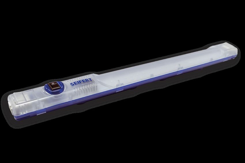
Table of Content 400176
1.   User manual ..................................................................................................................................   2
2.   Legal Regulations ........................................................................................................................       2
3.   Safety Instructions ......................................................................................................................       3
4.   Technical Data ..............................................................................................................................    4
5.   Mounting Principle .......................................................................................................................       5
6.   Cut Out Dimension .......................................................................................................................        5
7.   Electrical Connection ...................................................................................................................        6

     Version No. 1-1 - 19.01.2021                                 Doc. No. 99400176                                                         1/6
1. User manual
This instruction manual contains information and instructions to enable the user to work safely, correctly and
economically on the unit. Understanding and adhering to the manual can help one:
Avoid any dangers.
Reduce repair costs and stoppages.
Extend and improve the reliability and working life of the unit.
PLEASE ENSURE TO USE THE RIGHT VERSION OF THE INSTRUCTION MANUAL SUITABLE FOR YOUR
UNIT.
Intended use
The unit is to be used exclusively for the dissipation of heat from control cabinets and enclosures in order to
protect temperature sensitive components in an industrial environment. To meet the conditions of use, all the
information and instructions in the instruction manual must be adhered to.
General danger
Indicates compulsory safety regulations which are not
covered by a specific pictogram such as one of the following.
High electric voltage
Indicates electric shock danger.
Important safety instruction
Indicates instructions for safe maintenance and operation of
the unit.
Attention
Indicates possible burns from hot components.
Attention
Indicates possible damage to the unit.
Instruction
Indicates possible danger to the environment.
2. Legal Regulations
Liability
The information, data and instructions contained in this instruction manual are current at the time of going to
press. We reserve the right to make technical changes to the unit in the course of its development. Therefore,
no claims can be accepted for previously delivered units based on the information, diagrams or descriptions
contained in this manual. No liability can be accepted for damage and production caused by:
Version No. 1-1 - 19.01.2021 Doc. No. 99400176 2/6Disregarding the instruction manual
Operating error
Inappropriate work on or with the unit
The use of non-specified spare parts and accessories
Unauthorised modifications or changes to the unit by the user or his personnel
The supplier is only liable for errors and omissions as outlined in the guarantee conditions contained in the main
contractual agreement. Claims for damages on any grounds are excluded.
3. Safety Instructions
Upon delivery the unit is already meeting current technical standards and can therefore be safely taken into
operation. Only authorised personnel is allowed to work on the unit. Unauthorised personnel must be prohibited
from working on the unit. Operating personnel must inform their superiors immediately of any malfunction of
the unit.
Please note that before starting to work on or with the unit, a procedure must be carried out inside the cabinet
on which the unit is to be mounted.
Before commencing work inside the cabinet, the control cabinet manufacturer's instruction must be read with
regards to:
Safety instructions.
Instructions on taking the cabinet out of operation.
Instructions on the prevention of unauthorised cabinet reconnection.
The electric equipment meets the valid safety regulations. One can find dangerous voltages (above 50 V AC or
above 100 V DC)
Behind the control cabinet doors.
On the power supply in the unit housing.
The unit has to be operated according to the type plate and the wiring diagram, and must be protected
externally from overloading and electrical faults via suitable protective devices.
Danger through incorrect work on the unit
The unit can only be installed and maintained by technical competent and qualified personnel,
using only supplied material according to the supplied instructions.
Danger from electrical voltage
Only specialised personnel are allowed to maintain and clean the unit. The personnel must
ensure that for the duration of the maintenance and cleaning, the unit is disconnected from
the electrical supply.
Attention
Damage to the unit through the use of inappropriate cleaning materials. Please do not use
aggressive cleaning material.
Instruction
Damage to the environment through unauthorised disposal. All spare parts and associated
material must be disposed according to the environmental laws.
Version No. 1-1 - 19.01.2021 Doc. No. 99400176 3/64. Technical Data Order Number 400176 Operating Temperature Range -30°C -70°C Mounting Magnets / Clips Housing Material PC plastic Dimension A x B x C (D+E) 357.4 x 32 x 35.5 mm Weight 140 gr. Voltage / Frequency 120-230 V ~ 50/60 Hz Power Consumption 8 Watt Lamp LED, 120° angle, 7250K Luminosity 700 Lm Lifetime 50.000 hrs. @ 20°C Connection Wieland Connector Ingress Protection IP 20 Approvals CE, cURus Version No. 1-1 - 19.01.2021 Doc. No. 99400176 4/6
5. Mounting Principle

Safety Instructions

Read this instruction sheet before installing the light fixture.
Only specialised personnel are allowed to install, maintain and clean the fixture. The personnel must ensure that
for the duration of the installation, maintenance and cleaning the fixture is disconnected from the electrical
supply.

Installation

The light fixture is to be mounted indoors in a horizontal position as shown in the picture below and is to be
protected from the ingress of dust, water and corrosive agents. Use only the supplied mounting fasteners.

The door switch can be extended by a max. distance of 1.2”.

The supplied spacers can be used to adjust the vertical fixing position of the light fixture.

Spring channel nuts (#10-32) are also provided for channel mounting.

When installing a new tube take notice of the power enabled lamp holder (marked) on the fixture and fit the
corresponding end of the tube to it.

                                        6. Cut Out Dimension

   Version No. 1-1 - 19.01.2021                   Doc. No. 99400176                                        5/6
7. Electrical Connection
Check the serial label before making any connections to the power supply to ensure that current and voltage
ratings are met.
For convenience, the fixture has two power inlet/outlet terminal connectors. Power can be supplied to the either
of the two.
CAUTION: When one terminal connector is connected to the power supply the other will become LIVE. This
allows connecting multiple light fixtures to each other in a daisy chain. The optional NEMA 5-15 outlet socket
also becomes LIVE when either of the two terminal connectors is connected to the supply.
The electrical connections to the terminal connector are as follows:
1 Live
Earth
3 Neutral
IMPORTANT NOTES:
When connecting multiple fixtures to each other and to the NEMA 5-15 socket it is important that the total
current passing through the first light fixture (which supplies the others) does not exceed 12A.
The light fixture does not have an ON/OFF switch.
The door switch only discontinues the power supply to the tube. All other connectors remain LIVE unless the
power supply is disconnected (even if the tube is off).
Replacement bulbs for SCE-LF18/ SCE-LF18NO: T8 18” 8W LED, part no. SCE-LEDB18
Replacement bulbs for SCE-LF24/ SCE-LF24NO: T8 24” 10W LED, part no. SCE-LEDB24
Seifert Systems GmbH Seifert Systems Ltd. Seifert Systems AG Seifert Systems Inc. Seifert Systems Pty Ltd.
Albert - Einstein Str. 3 HF09/10 Wilerstrasse 16 75 Circuit Drive 105 Lewis Road
Hal-Far Industrial Estate North Kingstown Wantirna South
42477 Radevormwald Birzebbuga, BBG 3000 4563 Gerlafingen RI 02852 3152 Victoria
Germany Malta Switzerland United States Australia
Tel. +49 2195 68994-0 Tel. +356 2220 7000 Tel. +41 32 675 35 51 Tel. +1 401-294-6960 Tel. +61 3 98 01 19 06
Fax +49 2195 6899420 Fax +356 2165 2009 Fax +41 32 675 44 76 Fax +1 401-294-6963 Fax. +61 3 98 87 08 45
info.de@seifertsystems.com info@seifertsystems.com info.ch@seifertsystems.com info.us@seifertsystems.com info@seifertsystems.com.au
Version No. 1-1 - 19.01.2021 Doc. No. 99400176 6/6You can also read