INTELLIGENT MEDIUM POWERBAR - iMPB - E+I Engineering
←
→
Page content transcription
If your browser does not render page correctly, please read the page content below
INTELLIGENT MEDIUM
POWERBAR
iMPB
INTELLIGENT MEDIUM POWERBAR
iMPB

                                                          TECHNICAL FEATURES
                                                          iMPB is constructed from either high density 99.99%
                                                          conductivity copper or high density 55% conductivity
                                                          aluminium. The conductors are insulated with a custom
                                                          IEC certified thermoplastic material with outstanding
E+I Engineering’s Intelligent Medium Powerbar (iMPB) is
                                                          heat characteristics. The insulation has excellent
a 600 Volt encased track busway available with copper
                                                          dielectric strength and is impact resistant.
or aluminium conductors. The range is available in
two bar configurations from 160A to 800A. The bar is      iMPB is constructed with an aluminium housing providing
housed in an aluminium casing rated IP2X.                 a durable structure which also acts as a ground path.

Key features:                                             The iMPB range can be engineered with an over-rated
–	Unique open channel system allows tap offs to be       neutral option for busbar systems with non-linear loads.
    placed anywhere along the bar                         The additional neutral capacity prevents overloading
–	Solid joint pack construction                          caused by zero sequence harmonic currents.

–	Up to 4m lengths                                       E+I Engineering offer a 100% fully isolated ground for
–	Tap offs have mechanical/ electrical interlocks and   systems where earth isolation is required e.g. systems
    secure to the bar with an ‘earth first, break last’   with heavy microprocessors, based loads or large
    safety feature.                                       computer based installations.

                                                                                             Housing Size (inches)
                                                             Busbar Rating
                                                                (Amps)                    4 Pole                     5 Pole
                                                                 160A                   175 x 44mm                 210 x 44mm

                                                                 250A                   175 x 44mm                 210 x 44mm

                                                                 400A                   175 x 44mm                 210 x 44mm

                                                                 630A                   180 x 52mm                 215 x 52mm

                                                                 800A                   180 x 52mm                 215 x 52mm

                                                          Phase Configurations

                                                           Configuration     Phases                  Neutral             Earth
                                                               TP/N              100%                 100%               Case

                                                              TP/ON              100%                 170%               Case

                                                               TP/NE             100%                 100%               100%

                                                              TP/ONE             100%                 170%               100%

www.e-i-eng.com   1                                                                                            2    www.e-i-eng.com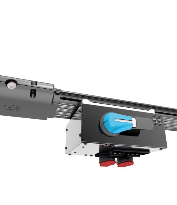
INTELLIGENT MEDIUM POWERBAR
iMPB

LENGTHS AND JOINTS
                                             Distribution lengths
                                             Distribution lengths are designed as an open track
                                             system; tap off units can be plugged in anywhere
                                             along the length of the busbar. The opening is
                                             finger safe meeting a rating of IP2X.

                                             Straight lengths can be supplied at any length from
                                             600mm - 4000mm.

                                             The iMPB joint pack securely locks two feeder
                                             lengths together with a traditional busbar bolted
                      Distribution Lengths   joint. No special tooling is required and joints may
                                             be disassembled and reassembled easily.

                                             iMPB uses custom designed thermally and
                                             electrically secure joint packs. Temperature
                                             monitoring of joints is available as an option.

                            Busway Joints

                                             End Feeds
                                             E+I Engineering can provide standard cable
                                             end boxes with options for cable entry from various
                                             points. Centre feeds and load bank feeds can also
                                             be supplied to meet specific project requirements.

                           Cable End Feed

www.e-i-eng.com   3                                                                                 4   www.e-i-eng.com
INTELLIGENT MEDIUM POWERBAR
iMPB
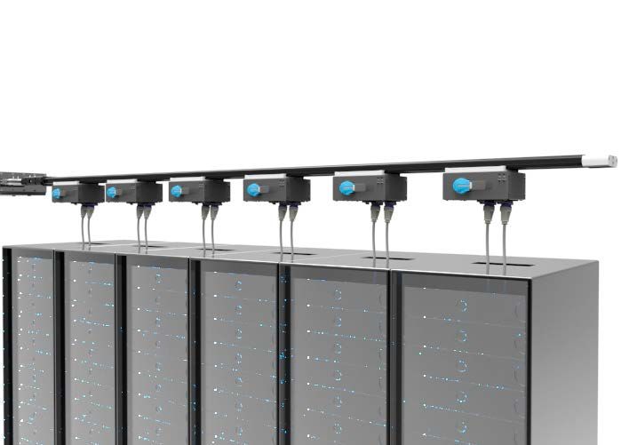
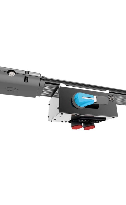
INSTALLATION TAP OFF UNITS
The modular design of iMPB iMPB tap off units are engineered with
allows it to be easily installed the safety of the installer and user as the
horizontally or vertically key criteria.
depending on specific
All tap off units have an ‘earth first, break last’ safety
project requirements.
feature and can be safely installed using Powerbar’s
Hanger brackets are supplied per length. SafeWork Technology.
These can be easily attached to drop
1. The units interlock onto the busway with a
rods for a seamless installation process.
ground strip. This ensures that the ground is the
iMPB can be connected directly to E+I first point of contact with the busbar system
Typical Underfloor Arrangement during installation.
Engineering’s High Powerbar (HPB) to
provide a full power solution.
2. The mechanical interlock secures the unit to
the bar using high tensile strength lockable
hardware which cannot be fitted incorrectly.
3. Once fitted to the bar, the engager handle
can be turned. This lifts the contacts into
the busway and has a positive lock once
fully rotated.
Key features:
– SafeWork Technology
– Individual tap-off units rated up to 125A
– Interlock feature ensures polarities do not
‘Hot Aisle Cold Aisle’ Arrangement mismatch
– Tap-off units can be fitted with IEC 309
receptacles, NEMA receptacles or whip cords
as required
Tap off units
HPB to iMPB Connection
www.e-i-eng.com 5 6 www.e-i-eng.comINTELLIGENT MEDIUM POWERBAR
iMPB
METERING TECHNICAL DATA
iMPB offers advanced metering which allows the user to monitor, integrate and display Technical Data
data centre power information via RJ45 Ethernet plug-in connections.
Rated Current (A) 160 250 400 630 800
Rated Operational Voltage (V) 600 600 600 600 600
Final circuit monitoring is integrated into
the busway to measure the total load of the Rated Insulation Voltage (V) 1000 1000 1000 1000 1000
busbar and tap off units. Power calculations Short Circuit
of total input power for each busway run can
Short Circuit Current Rating
25 25 30 36 35
also be provided. (rms symmetrical 1 second) KA
Peak Value (kA) 52.5 52.5 65 77 77
Options:
- Voltage for all three phases Short Circuit Conditional Rating (KAIC) 50 50 50 50 50
- Current - phase, ground and neutral Phase Conductor
- kW, KVa, kVAR, power factor, kWH
Cross Sectional Area (mm²) 122 122 210 255 320
Advanced options: Neutral Conductor
- Voltage total harmonic distortion
Cross Sectional Area (mm²) 122 122 210 255 320
- Overvoltage/ undervoltage alarm
threshold Isolated Ground Conductor
Daisy Chaining Meters
- Minimum and maximum current 100% Earth Cross Sectional Area (mm²) 122 122 210 255 320
- Demand and percentage load current
Housing Ground Path
- Crest factor
Cross Sectional Area (mm²) 1412 1412 1412 2030 2030
- Warning and alarm threshold
Overall Dimensions
It is also possible to monitor closed and trip
Height x Width of 4 Bar System (mm) 44 x 175 44 x 175 44 x 175 60 x 200 60 x 200
status for each MCB. The status signals are
fed back to the end feed using the integrated Weight
Ethernet cabling. The modules run in a daisy Weight of 4 Bar System (kg/m) 9.45 9.45 14.2 19.4 23.2
chain from meter to meter utilising the side
Resistance (R)
channel in the housing for cabling.
Resistance (mΩ/m) 0.173 0.173 0.108 0.098 0.078
Reactance (X)
Reactance (mΩ/m) 0.116 0.116 0.094 0.078 0.069
Impedance (Z)
Impedance (mΩ/m) 0.208 0.208 0.143 0.125 0.104
Voltage Drop at Full Load
Power Factor = 0.7 (V/m) 0.088 0.088 0.097 0.135 0.142
Power Factor = 0.8 (V/m) 0.087 0.087 0.096 0.134 0.141
Power Factor = 0.9 (V/m) 0.084 0.084 0.093 0.131 0.138
Power Factor = 1.0 (V/m) 0.090 0.090 0.099 0.137 0.144
www.e-i-eng.com 7 8 www.e-i-eng.comINTELLIGENT MEDIUM POWERBAR iMPB www.e-i-eng.com 9 10 www.e-i-eng.com
E+I Engineering Ltd.
                  European Manufacturing Location

                  Ballyderowen
                  Burnfoot
                  Co.Donegal
                  Ireland

                  Tel:
                  (UK) +44 (0)28 71353030
                  (ROI) +353 (0)74 9368719

                  Powerbar Gulf LLC
                  Middle East Manufacturing Location

                  N16/N17
                  Al Ghail Industrial Park
                  Ras Al Khaimah
                  PO Box 13229
                  UAE

                  Tel: +971 (0) 7221 6100

                  E+I Engineering USA Corp
                  USA Manufacturing Location

                  400 Supreme Industrial Drive
                  Anderson
                  South Carolina
                  29621

                  Tel: +1 864 375 1757

                  E+I Engineering Ltd.
                  UK Central Office

                  2/8 Victoria Avenue
                  London
                  EC2M 4NS

                  Tel: +44 (0)20 3206 1650

                  Email:
                  info@e-i-eng.com

WWW.E-I-ENG.COM

                                                 iMPB/IEC/MAY2020
You can also read