Assembly Instructions for a Motor Robot Car Kit 2WD, L298N Motor driver, HC-SC04 Ultrasonic module, Arduino - Stephen A. Edwards July 2018
←
→
Page content transcription
If your browser does not render page correctly, please read the page content below
Assembly Instructions for a Motor Robot Car Kit
         2WD, L298N Motor driver,
    HC-SC04 Ultrasonic module, Arduino
                Stephen A. Edwards

                    July 2018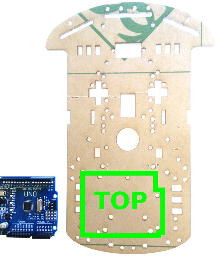
Search for “DIY L298N 2WD” on http://www.banggood.com.
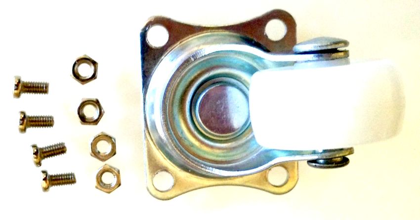
1   Mount the Swivel Wheel
    Parts Needed

    Swivel Wheel
    4 × 5 mm M3 screws
    4 × M3 nuts

    2 Determine the top of the baseplate; it is not symmetric. Use the Arduino as a guide.

    2 Attach the swivel to the bottom of the baseplate using the screws and nuts.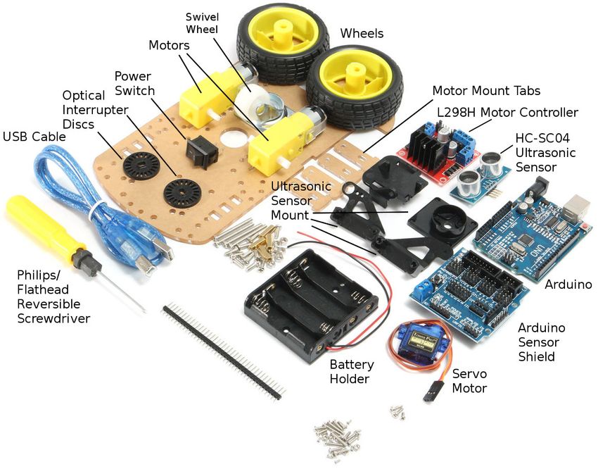
2   Mount the Arduino and Sensor Shield
    Parts Needed

    Arduino
    Sensor Shield
    2 × 10 mm M3 spacers
    4 × 5 mm M3 screws

    2 Connect the two spacers to the top of the baseplate using two screws

    2 Mount the Arduino on the spacers using the other two screws

    2 Mount the Sensor Shield atop the Arduino. Line up the right edges of the boards.
      Make sure each pin goes in a connector.
3 Mount the Motors on the Bottom of the Baseplate
Parts Needed
2 × motors
2 × 10 cm wires, black
2 × 10 cm wires, red
4 × acrylic tabs
4 × 30 mm M3 screws
4 × M3 nuts 2 × Wheels
2 Solder one red and one black wire to each motor. Either terminal can be either color.
2 Place one tab in a slot down from the top of the baseplate, align the motor, and place
the other tab on the slot on the side of the baseplate.
2 Insert two screws from the outside tab through the motor and inside tab and connect
the nuts.
2 Repeat the procedure for the other motor
2 Mount the wheels on the motors
2 (Optional) Attach the optical interruptor discs on the inside axles4 Mount the Switch, the Battery Holder, and L298N
Parts Needed
Rocker switch
L298N board
Battery holder
3 × 5 mm M3 screws
2 × 8 mm countersunk M3 screws
2 × 10 mm M3 spacers
1 × M3 nut
2 Insert the switch on the top of the baseplate between the two motors
2 Locate the battery holder on the underside of the baseplate just in front of the swivel
and insert the two countersuck M3 screws into the leftmost and rightmost holes.2 Connect one of the screws to the M3 nut and the other to a spacer 2 Connect the other spacer to the baseplate with a 5 mm M3 screw 2 Remove the three jumpers on the L298N board by pulling them up 2 Mount the L298N board to the two protruding spacers with the two other 5 mm screws.
5   Download the Firmware to Center the Servo
    Parts Needed

    Computer
    Servo Motor
    robot-car sketch
    USB cable

    2 Download and install the Arduino IDE from, e.g., http://www.arduino.cc/
    2 Start the Ardunio IDE on your computer.
    2 Open the “robot-car.ino” sketch (File → Open... → robot-car.ino)
    2 Make sure Tools → Board → Arduino Uno is selected

    2 Plug the servo motor connector into the column of pins labeled “11” on the Sensor
      Shield. Put the orange wire in the “S” row so the brown wire goes in the “G” row.

    2 Connect the USB cable between your computer and the Arduino
    2 Make sure a port is selected under Tools → Port
    2 Click on the “upload” button to compile and send your sketch to the Arduino
    2 Disconnect the USB cable once the program starts and centers the servo.
    2 Disconnect the servo connection from the Sensor Shield; we will re connect it later.
6 Assemble the Ultrasonic Sensor Mount
Parts Needed
Ultrasonic sensor base
Ultrasonic sensor sides
2 × 3 mm self-tapping screws
2 × 7 mm self-tapping screws
Servo motor
1 × 8 mm pan-head screw
White two-arm servo connector
2 Trim the two arms so they have only 3 holes and their ends are narrow enough to fit
in the base.
2 Fit the servo arm into the base and attach it with the two 3 mm self-tapping screws.
2 Use the panhead screw to attach the servo to the base2 Use the two 7 mm screws to connect the two halves to clamp the servo 2 Strap the ultrasonic sensor, pins up, to the mount with two twist ties looped around the two transducers
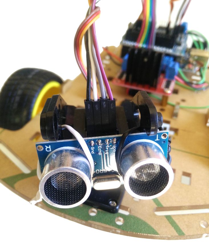
7   Attach the Ultrasonic Sensor to the Baseplate

    Parts Needed

    4 × 11 mm M1 screws
    4 × M1 nuts

    2 Attach the base of the ultrasonic sensor to the top of the baseplate with the screws
      and nuts.
8 Connect the power and motor wires
Parts Needed
1 × 20 cm length of wire, red
1 × 12 cm length of wire, red
1 × 12 cm length of wire, black
2 Solder the red wire from the battery holder to one switch terminal
2 Solder the 20 cm red wire to the other switch terminal
2 Connect the two left motor wires to the left connector on the L298N and the two right
motor wires to the right connector. Red and black do not matter here; reverse them if
the robot goes backwards.
2 Connect two 12 cm lengths of wire to the black (ground) wire from the battery holder
and the red (power) wire from the power switch.
2 Connect the doubled black (ground) wire to the “GND” terminal on the shield.
2 Connect the doubled red (power) wire to the “VCC” terminal on the shield.
2 Connect the black 12 cm wire from the shield terminal to the middle screw terminal
on the L298N.
2 Connect the red 12 cm wire from the shield terminal to the left screw terminal on the
L298N.9 Connect the Ultrasonic Sensor, Servo, and L298N to the Arduino Sensor Shield
Parts Needed
4 × 20 cm female-to-female jumper wires
7 × 10 cm female-to-female jumper wires
20 cm jumpers 3-pin servo cable 10 cm jumpers
HC-SR04 Pin Arduino Servo Arduino L298N Arduino
Gnd 12 G (Ground) Brown 11 G (Ground) ENA 6S
Echo 12 S Red 11 V (+5V) IN1 7S
Trig 13 S Orange 11 S IN2 5S
Vcc 13 V (+5V) IN3 4S
IN4 2S
ENB 3S
+5V 2 V (+5V)
Note Arduino
pin order10 Troubleshooting
2 Hold the robot off the ground and plug the USB cable between the Arduino and your
computer.
You should see power lights on the Arduino, the Sensor Shield, and the L298N motor
controller. If you don’t see all three lights, check the power wiring.
2 Shortly after the robot is turned on or reset, it centers the servo
If the servo does not move, verify you have connected the servo to location 11 and
the Orange wire is connected to “S.”
If the servo moves but isn’t in the center, remove the ultrasonic sensor mount from
the board, disconnect the servo from the base, and reattach the servo in the proper
location.
2 After centering the servo, the robot turns its left wheel forward then backward, then
its right wheel forward then backward.
If a wheel turns backwards, reverse its motor’s connection to the L298N board (swap
the red and black motor wires).
If one wheel turns but not the other, check the motor wiring and the wiring between
the Arduino and the L298N.
2 Disconnect the robot from the computer, turn off the power switch, and plug in 4 AA
batteries to the holder on the bottom. Turn on the power switch.
Again, you should see power lights on all three boards. If not, check the wiring
around the battery holder and the switch.11 Software Below and on the next few pages is the “robot-car.ino” sketch (software) that operates the car. This initial code indicates we will be using a servo motor and defines the pin numbers for the ultrasonic module, the servo motor, and the L298N motor controller. /* * Firmware for the ”2WD Ultrasonic Motor Robot Car Kit” * * Stephen A. Edwards * * Hardware configuration : * A pair of DC motors driven by an L298N H bridge motor driver * An HC−SR04 ultrasonic range sensor mounted atop a small hobby servo */ #include Servo servo ; // Ultrasonic Module pins const int trigPin = 13; // 10 microsecond high pulse causes chirp , wait 50 us const int echoPin = 12; // Width of high pulse indicates distance // Servo motor that aims ultrasonic sensor . const int servoPin = 11; // PWM output for hobby servo // Motor control pins : L298N H bridge const int enAPin = 6; // Left motor PWM speed control const int in1Pin = 7; // Left motor Direction 1 const int in2Pin = 5; // Left motor Direction 2 const int in3Pin = 4; // Right motor Direction 1 const int in4Pin = 2; // Right motor Direction 2 const int enBPin = 3; // Right motor PWM speed control
This code controls the two motors. The go function directs a particular motor to turn
forwards or backwards. For example, go(LEFT, 255) turns the left motor full forward;
go(RIGHT, -255) turns the right motor full reverse. The in1 and in2 pins control the direc-
tion of the left motor; in3 and in4 similarly control the right. The enA and enB pins control
the motor speed by affecting their duty cycle (how much of the time they are on).
enum Motor { LEFT, RIGHT };

// Set motor speed: 255 full ahead, −255 full reverse , 0 stop
void go( enum Motor m, int speed)
{
   digitalWrite (m == LEFT ? in1Pin : in3Pin , speed > 0 ? HIGH : LOW );
   digitalWrite (m == LEFT ? in2Pin : in4Pin , speed
This code controls the ultrasonic ranging sensor and servo. The readDistance function
triggers an ultrasonic “chirp,” causing a pulse on the trig pin whose duration indicates how
long it took the echo to return. The arithmetic converts the roundtrip time to millimeters.
// Read distance from the ultrasonic sensor , return distance in mm
//
// Speed of sound in dry air , 20C is 343 m/s
// pulseIn returns time in microseconds (10ˆ−6)
// 2d = p * 10ˆ−6 s * 343 m/s = p * 0.00343 m = p * 0.343 mm/us
unsigned int readDistance ()
{
digitalWrite ( trigPin , HIGH );
delayMicroseconds(10);
digitalWrite ( trigPin , LOW );
unsigned long period = pulseIn ( echoPin, HIGH );
return period * 343 / 2000;
}
The readNextDistance function handles scanning the ultrasonic sensor. It maintains the
distance array, which remembers how far away the robot things anything is at each of the
angles in the sensorAngle array. Each time readNextDistance is called, it measures and
stores the distance reported by readDistance then advances the servo to the next angle.
#define NUM ANGLES 7
unsigned char sensorAngle[NUM ANGLES] = { 60, 70, 80, 90, 100, 110, 120 };
unsigned int distance [NUM ANGLES];
// Scan the area ahead by sweeping the ultrasonic sensor left and right
// and recording the distance observed. This takes a reading , then
// sends the servo to the next angle . Call repeatedly once every 50 ms or so .
void readNextDistance ()
{
static unsigned char angleIndex = 0;
static signed char step = 1;
distance [angleIndex] = readDistance ();
angleIndex += step ;
if (angleIndex == NUM ANGLES − 1) step = −1;
else if (angleIndex == 0) step = 1;
servo . write ( sensorAngle[angleIndex] );
}The setup function runs once when the Arduino turns on or is reset. It sets each pin as
either an input or an output, then centers the servo (servo.write(90);), turns off the motors,
conducts a quick test of the motors, and does an initial scan of the surroundings with the
ultrasonic sensor.
// Initial configuration
//
// Configure the input and output pins
// Center the servo
// Turn off the motors
// Test the motors
// Scan the surroundings once
//
void setup () {
pinMode(trigPin , OUTPUT);
pinMode(echoPin, INPUT);
digitalWrite ( trigPin , LOW);
pinMode(enAPin, OUTPUT);
pinMode(in1Pin, OUTPUT);
pinMode(in2Pin, OUTPUT);
pinMode(in3Pin, OUTPUT);
pinMode(in4Pin, OUTPUT);
pinMode(enBPin, OUTPUT);
servo . attach ( servoPin );
servo . write (90);
go(LEFT, 0);
go(RIGHT, 0);
testMotors ();
// Scan the surroundings before starting
servo . write ( sensorAngle[0] );
delay (200);
for (unsigned char i = 0 ; i < NUM ANGLES ; i ++)
readNextDistance (), delay (200);
}Finally, here are the main rules governing the robot’s behavior. The loop function is called
repeatedly after setup has run. It uses readNextDistance to take the next a sonar reading and
update the distance array, then checks whether any reading in the distance array indicates
an object is too close. Any close-by object makes the robot back up and turn to the left by
turning on the left motor more than the right, otherwise, it turns on both motors full forward.
The delay at the end of this function limits this process to about 20 times a second.
// Main loop:
//
// Get the next sensor reading
// If anything appears to be too close , back up
// Otherwise, go forward
//
void loop () {
readNextDistance ();
// See if something is too close at any angle
unsigned char tooClose = 0;
for (unsigned char i = 0 ; i < NUM ANGLES ; i++)
if ( distance [ i ] < 300)
tooClose = 1;
if (tooClose) {
// Something's nearby: back up left
go(LEFT, −180);
go(RIGHT, −80);
} else {
// Nothing in our way: go forward
go(LEFT, 255);
go(RIGHT, 255);
}
// Check the next direction in 50 ms
delay (50);
}You can also read