2 International Tennis Federation
←
→
Page content transcription
If your browser does not render page correctly, please read the page content below
2

      ITF APPROVED TENNIS BALLS,

CLASSIFIED SURFACES & RECOGNISED COURTS

  A GUIDE TO PRODUCTS & TEST METHODS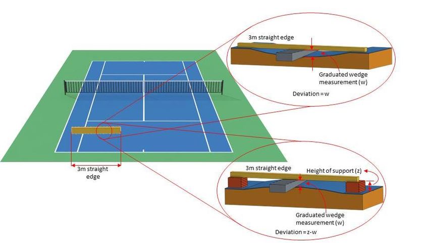
ITF APPROVED TENNIS BALLS, CLASSIFIED
SURFACES & RECOGNISED COURTS 2020
- a guide to products and test methods

Effective: 1 January to 31 December 2020

as approved/classified by:   International Tennis Federation

c/o The Technical Centre
ITF Licensing (UK) Ltd
Bank Lane
Roehampton
London SW15 5XZ
United Kingdom

Tel: +44 (0) 20 8878 6464
Email: technical@itftennis.com
Web: https://www.itftennis.com/en/about-us/tennis-tech/

             © ITF Licensing (UK) Ltd t/a International Tennis Federation
                                All rights reserved
                                        2020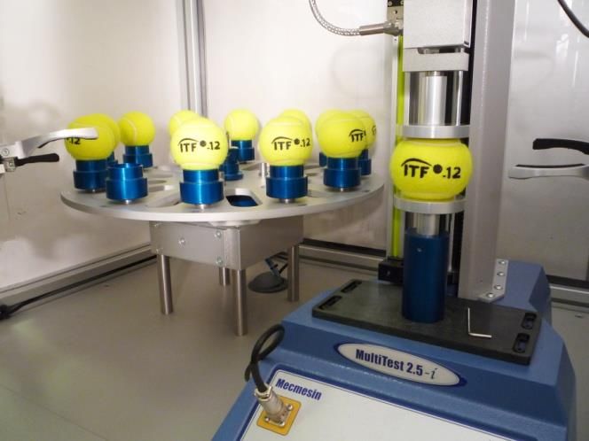
What is the International Tennis Federation?

The International Tennis Federation (ITF) is the world-wide governing body of tennis
and has the following broad areas of responsibility:
  •   administering and regulating the game.
  •   organising international competitions.
  •   structuring the game.
  •   developing the game.
  •   promoting the game.

The ITF Technical Commission is responsible for monitoring developments in
equipment technology in order to protect the nature of the game of tennis at all levels.
As custodians of the Rules of Tennis, the ITF has the sometimes difficult task of
judging whether innovations in tennis equipment may bring about a benefit to those
who play, or whether such developments constitute a threat to the nature of the game.

In 1997, the ITF created its own Technical Centre with a laboratory and staff whose
task it is to carry out testing and research into all aspects of the game, and to provide
support to the ITF Technical Commission and other ITF Committees on decisions
relating to technical issues. This facility is now a world-leading tennis research and
testing laboratory.

The mission of the ITF Technical Centre is:
       To protect the nature of tennis by actively preserving the skills
       traditionally required to play the game, and, to encourage innovation
       and improvements which maintain the challenge of the game and make
       it more exciting to play and watch.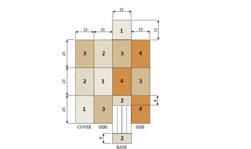
CONTENTS                                                                    Page

  (i)   Introduction                                                               3
 (ii)   The Rules of Tennis: Rule 3 The Ball and Appendix I: The Ball              5
(iii)   ISO 9001:2015                                                              7
(iv)    Future development of testing methods, tennis ball specifications          7
        and pace rating values

Part A: The Ball
1.    Regulations for the testing of tennis balls for ITF Approval
      1.1 General considerations                                                8
      1.2 Environmental conditions                                              9
      1.3 Laboratory and test equipment                                         9
      1.4 Test procedure                                                       13
      1.5 Calibration                                                          16
      1.6 Conditions for ITF Approval                                          18
      1.7 Market and tournament testing                                        18
2.    2020 ITF Approved Tennis Balls                                           19

Part B: ITF Guide to Test Methods for Tennis Court Surfaces
1.    Introduction                                                             20
2.    Key Properties                                                           22
3.    General Considerations                                                   23
4.    Court Pace (ITF CS 01/02)                                                26
5.    Ball Rebound (Predictive Method)                                         30
6.    Evenness (ITF CS 02/02)                                                  32
7.    Slope and Planarity (ITF CS 03/03)                                       36
8.    Dimensions (ITF CS 04/02)                                                39

Part C: Court Pace Classification
1.    Court Pace Classification Programme
      1.1 Introduction                                                         42
      1.2 Application to an ITF Accredited laboratory                          42
      1.3 Application for ITF Classification listing                           43
2.    ITF Classified Surfaces                                                  45

                                          1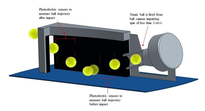
Page
Part D: ITF Recognised Tennis Courts
1.    Introduction                                                        47
2.    ITF Recognition                                                     48
      2.1 One-Star ITF Recognition                                        48
      2.2 Two-Star ITF Recognition                                        48
3.    Approval of companies to conduct One-Star ITF Recognition tests     49
4.    Accreditation of laboratories                                       49
       4.1 Criteria for accreditation                                     49
       4.2 Application for ITF accreditation                              50
5.     Procedures and fees for obtaining ITF Recognition                  51
6.     Validity of ITF Recognition                                        52
7.     ITF Recognition Supplier Status                                    52

                                      2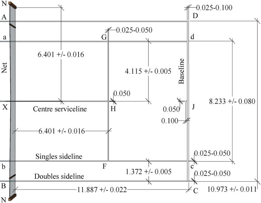
(i) INTRODUCTION

The Rules of Tennis requires that any ball which is used in any tournament which is
played according to the Rules of Tennis, shall be named on the official list of balls
which have been tested and approved as conforming to the specifications laid down in
the Rules of Tennis and as issued by the International Tennis Federation (ITF).

The Rules of Tennis (see Rule 3 and Appendix I) provide for seven types of ball – a
fast-speed ball (Type 1), the standard (Type 2) ball, a slow-speed ball (Type 3) and a
High Altitude ball, in addition to Stage 3, 2 and 1 balls. These are designed to have
different performance characteristics derived from their dynamic and aerodynamic
properties. It should be noted that the Type 3 ball is also permitted and recommended
for play at high altitude on any court surface type.

To help determine which ball should be used on which surface, the ITF introduced an
official Court Surface Classification Scheme (CSCS) in 2000, which was superseded
by the Court Pace Classification Programme (CPCP) from January 2008. This change
followed a two-year research project by the ITF Technical Centre that culminated in the
development of Court Pace Rating, which provides better agreement between
theoretical measurements and player perception of pace than for its predecessor
(Surface Pace Rating).

To enable the properties of equipment to be measured in accordance with accepted
scientific standards using the SI system, all products are approved or assessed for
conformity against the specifications and tolerances given or implied in the SI unit as
stated in the current edition of the Rules of Tennis.

Tennis ball approval and the Court Pace Classification Programme have been
introduced as part of an initiative to provide further understanding and international
standardisation of the equipment used in tennis. They will be of significance to players,
National Associations, Referees, tournament organisers and tennis ball manufacturers
worldwide.

The ITF Technical Centre commenced testing for ITF Approval for the calendar year
2020 on 1 June 2019. The testing procedure for balls which are to be included on the
official list of 2021 ITF Approved balls will commence on 1 June 2020.

The testing of court surface products is undertaken by ITF Accredited Laboratories. ITF
Court Pace Classification is valid for a period of three years.

The definitive list of current ITF Approved balls and ITF Classified surface products
can be found on the ITF website ( https://www.itftennis.com/en/about-us/tennis-tech/).

Companies requiring detailed information on the procedures for applying for, and
receiving, ITF Approval for tennis balls, ITF Court Pace Classification and ITF
Recognition should contact the ITF Technical Centre.

                                           3
(ii) THE RULES OF TENNIS – RULE 3 AND APPENDIX I – THE BALL
 (Effective 1 January 2020)

Balls, which are approved for play under the Rules of Tennis, must comply with the
specifications in Appendix I.

The International Tennis Federation shall rule on the question of whether any ball or
prototype complies with Appendix I or is otherwise approved, or not approved, for play.
Such ruling may be taken on its own initiative or upon application by any party with a bona
fide interest therein, including any player, equipment manufacturer or National Association
or members thereof. Such rulings and applications shall be made in accordance with the
applicable Review and Hearing Procedures of the International Tennis Federation (see
Appendix XI).

The event organisers must announce in advance of the event:
a.    The number of balls for play (2, 3, 4 or 6).
b.    The ball change policy, if any.

Ball changes, if any, can be made either:
   i.     After an agreed odd number of games, in which case, the first ball change in the
          match shall take place two games earlier than for the rest of the match, to make
          allowance for the warm-up. A tie-break game counts as one game for the ball
          change. A ball change shall not take place at the beginning of a tie-break game.
          In this case, the ball change shall be delayed until the beginning of the second
          game of the next set; or
   ii.    At the beginning of a set

If a ball gets broken during play, the point shall be replayed.

Case 1: If a ball is soft at the end of a point, should the point be replayed?
Decision: If the ball is soft, not broken, the point shall not be replayed.

Note: Any ball to be used in a tournament which is played under the Rules of Tennis must
be named on the official ITF list of approved balls issued by the International Tennis
Federation.

                               APPENDIX I – THE BALL

For all measurements in Appendix I, SI units shall take precedence.

a. The ball shall have a uniform outer surface consisting of a fabric cover, except for
   the Stage 3 (Red) foam ball. If there are any seams they shall be stitchless.

b. The ball shall conform to one of the types specified in the table immediately below
   or in the table under paragraph (d).

                                               4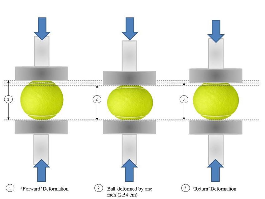
TYPE 1               TYPE 2                  TYPE 3                 HIGH
                            (FAST)            (MEDIUM)1                (SLOW)2             ALTITUDE3
    MASS (WEIGHT)      56.0-59.4 grams      56.0-59.4 grams        56.0-59.4 grams        56.0-59.4 grams
                         (1.975-2.095         (1.975-2.095           (1.975-2.095           (1.975-2.095
                            ounces)              ounces)                ounces)                ounces)
    SIZE                 6.54-6.86 cm         6.54-6.86 cm           7.00-7.30 cm           6.54-6.86 cm
                      (2.57-2.70 inches)   (2.57-2.70 inches)     (2.76-2.87 inches)     (2.57-2.70 inches)
    REBOUND               138-151 cm           135-147 cm             135-147 cm             122-135 cm
                        (54-60 inches)       (53-58 inches)         (53-58 inches)         (48-53 inches)
    FORWARD             0. 56-0.74 cm         0.56-0.74 cm           0.56-0.74 cm           0.56-0.74 cm
    DEFORMATION4         (0.220-0.291         (0.220-0.291           (0.220-0.291           (0.220-0.291
                            inches)              inches)                inches)                inches)
    RETURN               0.74-1.08 cm         0.80-1.08 cm           0.80-1.08 cm           0.80-1.08 cm
    DEFORMATION4         (0.291-0.425         (0.315-0.425           (0.315-0.425           (0.315-0.425
                            inches)              inches)                inches)                inches)
    COLOUR             White or Yellow      White or Yellow        White or Yellow        White or Yellow

Notes:
1
  This ball type may be pressurised or pressureless. The pressureless ball shall have an
internal pressure that is no greater than 7 kPa (1 psi) and may be used for high altitude
play above 1,219 m (4,000 feet) above sea level and shall have been acclimatised for
60 days or more at the altitude of the specific tournament.
2
 This ball type is also recommended for high altitude play on any court surface type
above 1,219 m (4,000 feet) above sea level.
3
  This ball type is pressurised and is specified for high altitude play above 1,219 m
(4,000 feet) above sea level only.
4
  The deformation shall be the average of a single reading along each of three
perpendicular axes. No two individual readings shall differ by more than 0.08 cm (0.031
inches).

c. In addition, all ball types specified under paragraph (b) shall conform to the
   requirements for durability as shown in the following table:

                MASS (WEIGHT)              REBOUND                FORWARD                 RETURN
                                                                DEFORMATION            DEFORMATION
     MAXIMUM           0.4 grams              4.0 cm                0.08 cm                0.10 cm
     CHANGE1        (0.014 ounces)         (1.6 inches)          (0.031 inches)         (0.039 inches)

Notes:
1
  The largest permissible change in the specified properties resulting from the durability
test described in the current edition of ITF Approved Tennis Balls, Classified Surfaces
& Recognised Courts. The durability test uses laboratory equipment to simulate the
effects of nine games of play.

d. Only the ball types specified in the table below can be used in 10 and under tennis
   competition:

                                                   5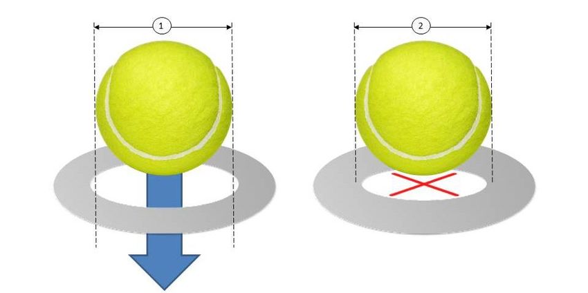
STAGE 3              STAGE 3                STAGE 2             STAGE 1
                             (RED)               (RED)               (ORANGE)             (GREEN)
                            FOAM              STANDARD             STANDARD³            STANDARD
    MASS (WEIGHT)          25.0-43.0        36.0-49.0 grams       36.0-46.9 grams     47.0-51.5 grams
                         (0.882-1.517         (1.270-1.728          (1.270-1.654        (1.658-1.817
                            ounces)              ounces)               ounces)             ounces)
    SIZE                 8.00-9.00 cm         7.00-8.00 cm          6.00-6.86 cm        6.30-6.86 cm
                      (3.15-3.54 inches)   (2.76-3.15 inches)   (2.36-2.70 inches)   (2.48-2.70 inches)
    REBOUND               85-105 cm            90-105 cm             105-120cm           120-135 cm
                        (33-41 inches)       (35-41 inches)        (41-47 inches)      (47-53 inches)
    FORWARD                                                         1.40-1.65 cm        0.80-1.05 cm
    DEFORMATION1            -------              -------            (0.551-0.650        (0.315-0.413
                                                                       inches)             inches)
    COLOUR2                                Red and yellow,      Orange and yellow,
                                                                                       Yellow with a
                            Any            or yellow with a      or yellow with an
                                                                                         green dot
                                               red dot               orange dot

Notes:
1
  The deformation shall be the average of a single reading along each of three
perpendicular axes. There is no limit on the difference between individual forward
deformation readings. There is no specification for return deformation.
2
    All coloured dots shall be reasonable in size and placement.
³ For a one-year trial (from 1 January to 31 December 2020), alternative colours to those
specified in this table may be used for Beach Tennis only (e.g. blue and yellow, purple
and yellow, purple and orange, purple and green). Note: information on this trial is
included in this booklet for the benefit of beach tennis ball suppliers and has not been
included in the 2020 Rules of Tennis.

e. All tests for rebound, mass, size, deformation and durability shall be made in
   accordance with the Regulations described in the current edition of ITF Approved
   Tennis Balls, Classified Surfaces & Recognised Courts.

                        CLASSIFICATION OF COURT PACE

The ITF test method used for determining the pace of a court surface is ITF CS 01/02 (ITF
Court Pace Rating) as described in the ITF publication entitled “ITF guide to test methods
for tennis court surfaces”.

Court surfaces which have an ITF Court Pace Rating of 0 to 29 shall be classified as being
Category 1 (slow pace). Examples of court surface types which conform to this classification
will include most clay courts and other types of unbound mineral surface.

Court surfaces which have an ITF Court Pace Rating of 30 to 34 shall be classified as being
Category 2 (medium-slow pace), while court surfaces with an ITF Court Pace Rating of 35
to 39 shall be classified as being Category 3 (medium pace). Examples of court surface types
which conform to this classification will include most acrylic coated surfaces plus some
carpet surfaces.

                                                 6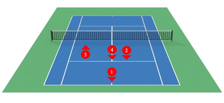
Court surfaces with an ITF Court Pace Rating of 40 to 44 shall be classified as being
Category 4 (medium-fast pace), while court surfaces which have an ITF Court Pace Rating
of 45 or more shall be classified as being Category 5 (fast pace). Examples of court surface
types which conform to this classification will include most natural grass, artificial grass and
some carpet surfaces.

Case 1: Which ball type should be used on which court surface?

Decision: 3 different types of balls are approved for play under the Rules of Tennis,
however:
a. Ball Type 1 (fast speed) is intended for play on slow pace court surfaces
b. Ball Type 2 (medium speed) is intended for play on medium-slow, medium and
   medium-fast pace court surfaces
c. Ball Type 3 (slow speed) is intended for play on fast pace court surfaces

Note:
In addition to the ball types specified under paragraph (b) above, the Stage 1 (Green)
ball may be used for all levels of competitive play except for world ranking professional
tennis events, Davis Cup and Fed Cup, Junior Tournaments and Team events sanctioned
by the ITF and affiliated Regional Associations, ITF Senior Circuit and Team events
and ITF Wheelchair Circuit and Team events. Each National Association shall have the
right to decide which national competitive events should use the Stage 1 (Green) ball.

(iii) ISO 9001:2015

All testing, administration and calibration procedures adopted by the ITF Technical
Centre in testing tennis balls for ITF Approval, surface products for ITF Classification,
and courts for ITF Recognition are carried out and managed according to
ISO 9001:2015

(iv) FUTURE DEVELOPMENT OF TESTING METHODS, TENNIS
 BALL SPECIFICATIONS AND COURT PACE RATING VALUES

The ITF reserves the right to amend and update the information given in this document
without prior notice. As a general rule, amendments will be made only after consultation
with interested parties.

                                               7
PART A – THE BALL
1. REGULATIONS FOR THE TESTING OF TENNIS BALLS
FOR ITF APPROVAL
The properties of tennis balls are specified by the International Tennis Federation to
generate uniformity, and consistency in performance. Special testing facilities and
apparatus are necessary to accurately measure these properties, and this section details
the required test conditions and procedures.
The following notes are provided as additional information for those involved in the
testing or evaluation of tennis balls and should be read in conjunction with the
specification for a tennis ball, as described in Rule 3 and Appendix I of the Rules of
Tennis.
1.1 General Considerations
With the exception of Stage 3 moulded foam and cut foam types, a tennis ball consists
of a hollow rubber core (which may or may not be pressurised) covered by a textile
material composed of wool, nylon and cotton. Because the properties of the rubber core
and its internal gas are affected by temperature, the properties of the cover by
atmospheric moisture, and the effective internal pressure by the external atmospheric
pressure, it is important that ball testing is carried out in a controlled environment where
at least temperature and humidity are standardised. While it is not practical to control
atmospheric pressure, it is desirable that any testing station should be at or near sea level
so that test data are comparable. In any case, atmospheric pressure should always be
recorded when ball tests are made.
The following conditions are specified for testing by the ITF (the “Controlled
Environment”):
Temperature 20 ± 2C (68F)
Relative humidity 60 ± 5%
Atmospheric pressure 102 ± 3 kPa (30 inches Hg)
Other Controlled Environment standards may be fixed for localities where one or more
of the average temperature, humidity and average barometric pressure at which the
game is being played differ materially from 20º Celsius (68º Fahrenheit), 60% relative
humidity and 102 kPa (30 inches Hg) respectively.
Applications for such adjusted standards may be made by any National Association to
the ITF and, if approved, shall be adopted for such localities.
81.2 Environmental Conditions
To meet the Controlled Environment requirements noted above, a well-insulated room
with double-glazed windows not exposed to direct sunshine, and a double-door ‘air-
lock’ arrangement to reduce air leakage on entry and exit, are recommended.
Control of temperature and humidity should be provided by a temperature and humidity
control unit of an appropriate specification with regard to thermal capacity and control
accuracy. Such a conditioner normally consists of two component parts: an internal fan
unit and an external condenser unit with connecting piping.
The specification of this conditioning equipment is primarily related to removing excess
heat and moisture generated within the environment by electrical equipment and the
bodies of the technicians working there. Such equipment must be capable of controlling
the testing environment within the tolerances set down in Section 1.1.
As well as controlling the environment, the conditioning equipment should also be
independently monitored, and so temperature and humidity recorders together with a
barometer are necessary. A permanent record of environmental conditions during
conditioning and testing should be kept.
Balls selected for testing should be stored under such controlled conditions and exposed
to circulating air for ‘conditioning’ for a minimum of 24 hours prior to testing.
1.3 Laboratory and Test Equipment
Mass – Test Method ITF TB 01/01: An electronic laboratory balance measuring in
grams to at least two decimal places, to a capacity of 100 grams.
Size – Test Method ITF TB 02/01: Two ring gauges with diameters of the upper and
lower limits for the respective ball. In all tests for diameter, the ring gauge used shall
consist of a metal plate (preferably non-corrosive) of uniform thickness of 0.318 cm
(0.125 inches). In the case of Type 1 (fast speed) and Type 2 (medium speed) balls,
plates with circular openings measuring 6.54 cm (2.57 inches) and 6.86 cm
(2.70 inches) in diameter respectively shall be used. In the case of Type 3 (slow speed)
balls, plates with circular openings measuring 7.00 cm (2.76 inches) and 7.30 cm
(2.87 inches) in diameter respectively shall be used. In the case of Stage 1 balls, plates
with circular openings measuring 6.30 cm (2.48 inches) and 6.86 cm (2.70 inches) in
diameter respectively shall be used. The inner surface of the gauge shall have a convex
profile with a radius of 0.160 cm (0.063 inches). See Figure 1.
Deformation – Test Method ITF TB 03/01: A modified Stevens Machine (i.e. one
which measures forward deformation and return deformation) capable of applying a
force along a diameter of a ball, and measuring the resulting deformation.
9Prior to deformation testing, the ball must be pre-compressed through a distance of
2.54 cm (1.0 inches) three times on each of three perpendicular axes in order to remove
any ‘set’ in the ball. One pre-compression should occur on each axis in succession, until
nine pre-compressions in all are completed. This is carried out on a pre-compression
jig. See Figure 2.
(1) A ball must pass through a ring gauge (2) A ball must not pass through a ring gauge
(under its own weight) with an internal (under its own weight) with an internal
diameter of: diameter of:
Ball Type 1 & Type 2: 6.86 cm (2.70 inches) Ball Type 1 & Type 2: 6.54 cm (2.57 inches)
Ball Type 3: 7.30 cm (2.87 inches) Ball Type 3: 7.00 cm (2.76 inches)
Stage 1 (Green) ball: 6.86 cm (2.70 inches). Stage 1 (Green) ball: 6.30 cm (2.48 inches).
Figure 1. Size – Test Method ITF TB 02/01.
Figure 2. Pre-Compression – Test Method ITF TB 03/01.
10An approved machine shall compromise the following: A first rigid platen connected to
a force-measuring device and a second identical and parallel platen which can move
axially with respect to the first platen, such that when a ball is placed between them it
can be compressed along its diameter between the platens and measurement taken of its
deformation at a predetermined force. The platen design shall be as shown in Figure 3.
Note: The Stevens machine is deemed to be compliant with the above.
Figure 3. Deformation – Test Method ITF TB 03/01. Specification of platen
design (to be used for both platens). All dimensions are given in millimetres.
Rebound – Test Method ITF TB 04/01: The ball is dropped from a height of
254 ± 0.3 cm (100 ± 0.1 inches) (measured from the bottom of the ball) onto a smooth,
rigid and horizontal block of high mass and the rebound height is measured (again to
the bottom of the ball). See Figure 4.
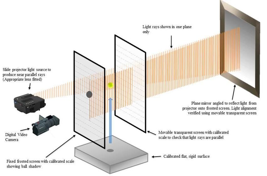
11Figure 4. Rebound – Test Method ITF TB 04/01.
To ensure sufficient accuracy of the rebound measurement, the following method is
recommended. A shadow of the ball produced by a parallel and horizontal beam of light
is cast onto a vertical frosted screen incorporating a graduated calibrated scale. Images
of the shadow are captured by a video camera, and the trajectory of the ball analysed
such that its highest point with reference to the calibrated scale can be identified.
Durability – Test Method ITF TB 05/01: The ball is projected such that it impacts a
smooth, rigid surface mounted at 90 ± 10° to its trajectory at 40 ± 3 m/s with 3 rev/s
spin. This procedure shall be repeated until the ball has undergone 20 impacts. The ball
shall then be placed in a felt-wearing device, with a second ball, for a period of
2 minutes. This wearing procedure (the “wearing regime”) may be performed outside
of the Controlled Environment. Following this procedure, the ball is conditioned in the
Controlled Environment for a minimum of 24 hours and then retested for rebound, size,
mass and deformation in accordance with the procedures described herein.
In all tests for durability, the felt-wearing device shall consist of a box lined with
medium grade emery paper (which shall be obtained from the ITF), and inclined at 23°
to the horizontal, with three rotating wooden spigots at the lowest point. The internal
dimensions of the box shall measure 15 ± 1 cm by 15 ± 1 cm and 69 ± 1 cm in length.
Each spigot shall measure 19 ± 1 cm in length and 2.0 cm in diameter, and shall be
rounded at both ends with a radius of 1.0 cm. The angle between the spigots, measured
about the centreline of the axle, shall be 60°. The distance between the centrelines of
adjacent spigots shall measure 4.5 cm. Each spigot shall protrude 4.0 cm into the box,
when parallel to the bottom end face of the box, and the centreline of the spigot shall
measure 3.0 cm to the aforementioned face when in this position. The angular velocity
of the spigots shall be 500 ± 50 rpm. See Figure 5.
12Figure 5. Durability – Felt wearing device for test method ITF TB 05/01.
All dimensions are given in centimetres.
Size (Durability) – Test Method ITF TB 06/01: A drop gauge measuring in
centimetres to at least three decimal places, to a capacity of 10 cm. The contact foot of
the drop gauge shall be a circular metal disc of diameter 1.2 ± 0.1 cm.
1.4 Test Procedure
From the 72 balls submitted for approval (36 balls for Stage 2 and Stage 3), the ITF
randomly selects 24 for testing (12 balls for Stage 2 and Stage 3). The ball containers
are opened and the balls are then stored on racks in the Controlled Environment for a
minimum of 24 hours prior to testing. Each ball should be individually marked
(preferably with a permanent marker) so that test results can be assigned to a particular
ball.
Following visual inspection, the test procedure should be carried out on each ball in the
following sequence:
i. Pre-compression. Apply to each of the three axes in succession, as described in
Section 1.3. All subsequent tests are to be completed within two hours of pre-
compression.
13ii. Mass. Record the mass displayed in grams and round to one decimal place.
iii. Size. Use ring gauges across at least three mutually perpendicular diameters. For all
ball types, the ball shall not drop through the smaller opening by its own weight in
any orientation and shall drop through the larger opening by its own weight in all
orientations. Care should be taken to ensure that the ball relies only upon its own
weight to pass through a ring. Record Pass/Fail.
Size (Durability). The ball shall rest under its own weight directly below the contact
foot of the drop gauge. A vertical load of approximately 0.5 N is applied to the ball
by the contact foot. The reading is recorded 5 seconds after the load is applied. The
ball diameter shall be the average of a single reading along each of three
perpendicular axes, reported in centimetres to two decimal places.
The ‘Go/No-Go’ method (described above) serves as the pass/fail criterion for
absolute size.
iv. Deformation. Test once on each axis and record the results. Report the mean value,
and the maximum difference between the three readings1, for each ball (see also
Section 1.3). The test measures the deformation of a ball under a load of
80.07 ± 0.5 N (18.00 ± 0.1 lbf) after an initial ‘contact’ load, of 15.57 ± 0.5 N
(3.50 ± 0.1 lbf), has been applied to compress the fabric cover material. See Figure 6.
The ‘deformation’ is measured in two senses:
a. When the load is first applied (forward deformation).
b. Under the action of the load prior to it being removed and after the ball has been
compressed further through a total distance of 2.54 cm (1.0 inches) (return
deformation).1
The ball is placed in position so that neither platen of the machine is in contact with
the cover seam. A contact load of 15.57 ± 0.5 N (3.50 ± 0.1 lbf) is applied and the
displacement of the platens under this load becomes the datum for the deformation
readings. A constant platen speed of 200 mm/min (7.87 inches/min) is then applied
up to an additional load of 80.07 ± 0.5 N (18.00 ± 0.1 lbf). The total test load is
therefore 95.64 ± 0.5 N (21.50 ± 0.1 lbf). The total test load is held for 5 seconds
before the forward deformation reading is recorded. The constant platen speed is then
resumed to produce a deformation of 2.54 cm (1.0 inch), and then immediately
reversed until it reaches the test load (95.64 ± 0.5 N). The test load is held for
10 seconds before the return deformation is recorded. The load is then completely
removed at the constant platen speed. This procedure is repeated on each ball across
the two diameters at right angles to the initial position and to each other.
1
There is no specification for the maximum difference between the three readings for
forward deformation for Stage 1 balls.
14Figure 6. Deformation – Test Method ITF TB 03/01.
Automated compression machine
The automated compression machine (pictured below) has been developed by the
ITF as an alternative to the Stevens machine for testing tennis ball deformation.
The computer-controlled machine replicates the operation of the Stevens machine,
but provides the following improvements over the Stevens machine:
a. Elimination of operator error in speed and timing of testing.
b. Reduction of backlash (unmeasured movements due to machining tolerance and
wear).
c. Graphical display of useful comparative information such as hysteresis losses.
d. Carousel feed allowing up to 12 balls to be tested in three axes without operator
assistance.
e. The machine can also be used to pre-compress balls according to the Rules of
Tennis.
All of these advantages give the automated machine more functionality, accuracy
and better reproducibility of results than the Stevens machine. For further
information on automated compression machines, contact the ITF Technical Centre.
15v. Rebound. Record four valid measurements per ball (disregarding bounces that
deviate significantly from vertical) and report mean rebound height in centimetres to
one decimal place.
vi. Internal pressure.
a. Packaging. All sealed packaging is measured using a standard pressure gauge
with needle attachment and rubber seal.
b. Ball. Four balls are tested. Measurements are taken using a standard pressure
gauge with needle attachment.
Note: This test does not apply to Stage 2 and Stage 3 balls.
vii. Durability. Select six balls at random from the sample that was tested for approval.
Apply the wearing regime described in Section 1.3. Visually inspect the balls for
signs of detachment of the fabric cover, and cracks or ruptures. Record the results for
mass, size, deformation and rebound, as described in paragraphs (i) to (v) above.
Report the change in the specified properties from the original results for each test.
Note: This test does not apply to Stage 1, Stage 2 and Stage 3 balls.
1.5 Calibration
The apparatus used for the various tests must be regularly checked for accuracy of
calibration as follows:
Size. The ring gauges should be checked for accuracy against a known traceable
reference every two years. The tolerance on ring gauge diameter should be ± 0.0064 cm
(0.0025 inches).
Size (Durability). The drop gauge should be checked monthly with calibrated slip
gauges. The accuracy of the drop gauge should be ± 0.002 cm.
Mass. The weighing scales should be checked with calibration weights monthly. The
accuracy of the scales should be ± 0.01 g.
Rebound. Where the ‘video’ system is used for measuring rebound, the horizontal
alignment of the light beam must be checked at the beginning and end of each test
sequence. The accuracy of drop height and the frosted and transparent scales should be
checked monthly. The accuracy of the drop height and both scales should be ± 0.3 cm
(0.1 inches).
Pressure. Pressure gauges should be checked for accuracy annually. The accuracy of
the gauges should be ± 0.3 kPa (0.04 psi).
Deformation. The Stevens machine should be checked daily for beam balance with the
contact weight removed. It should be checked also for accuracy of platen displacement
16twice per year using 60 mm slip gauges. The accuracy of platen displacement should be
± 0.008 cm. The automated compression machine, including the load cell and platen
displacement, should be checked for accuracy against a known traceable reference
annually. The accuracy of the load cell should be ± 0.2% over the full scale of its
operation (0-1 kN) and the platen displacement should be ± 0.008 cm.
Durability. The velocity of ball projection should be checked monthly. The spin rate
of ball projection should be checked every two years. The angular velocity and size of
the spigots in the felt-wearing device should be checked annually. Tolerances are
provided in the Durability Test Method above. The emery paper should be replaced
using the following protocol (refer to Figure 7):
a. After 16 hours of testing, replace only the pieces labelled number 1 using new pieces
of evenly-cut medium grade emery paper (obtained from the ITF) and adhesive spray
or adhesive tape applied to the reverse. Ensure that there is no overlap or gap between
adjacent pieces.
b. After a further 16 hours of testing, replace only the pieces labelled number 2 as
described above.
c. After a further 16 hours of testing, replace only the pieces labelled number 3 as
described above.
d. After a further 16 hours of testing, replace only the pieces labelled number 4 as
described above.
e. Return to step (a).
Figure 7. Schematic diagram of the locations of emery paper in the felt-wearing
device (net drawing from above). All dimensions are given in centimetres.
171.6 Conditions for ITF Approval
All manufacturers that wish their ball brand(s) to be considered for inclusion on the
annual list of ITF Approved tennis balls must submit a sample of such brand(s) for
testing by the ITF in the manner described above. The sample of balls submitted must
conform to the Rules of Tennis in all respects in order for ITF Approval to be granted.
The markings on the ball and its packaging must be appropriate for tennis. Further
details on the eligibility of ball markings and packaging can be found in the current ITF
Ball Approval procedures, available to download from
https://www.itftennis.com/en/about-us/tennis-tech/approved-balls/.
A ball which is granted ITF Approval is approved by the ITF only on the basis that it
has been found to conform to the current Rules of Tennis and is therefore considered
suitable for use in tournaments played according to the Rules of Tennis. ITF Approval
does not imply any other form of approval.
The ITF reserves the right to withdraw ITF Approval from any tennis ball brand(s) at
any time if it finds that balls are substantially different from the sample(s) submitted for
approval or, in the opinion of the ITF Technical Commission, such balls are not
designed to meet the specification laid down in the Rules of Tennis, or if the approved
balls otherwise fail to meet a reasonable quality standard.
1.7 Market and tournament testing
The ITF has additional specific requirements for tennis balls which have been granted
ITF Approval, to ensure that such balls continue to meet the standards laid down in the
Rules of Tennis. Such balls may be obtained and tested from any source world-wide at
the sole discretion of the ITF. ITF Approved balls are required to meet certain criteria,
as described below, in order to retain ITF Approved status.
The minimum sample size for balls tested under this procedure is 12. A ball which fails
to conform to one or more of the specifications laid down in the Rules of Tennis will
be counted as a single failure. The criteria by which samples of balls will be assessed
are as follows:
No. of balls No. of balls failing
in sample to conform Action
0-1 None
12 2-3 Letter of warning
4+ 1 point towards removal of
ITF Approval
0-2 None
24 3-7 Letter of warning
8+ 2 points towards removal
of ITF Approval
18The above criteria are based on the normal distribution curve with action being taken in
the form of either a warning letter to the manufacturer/distributor, or points towards
removal of ITF Approval at ± 1 and ± 2 standard deviations from the mean respectively.
Criteria for other sample sizes are calculated accordingly.
a. If the number of failures in a single brand in any samples totalling at least 72
results in the accrual of six points towards removal of ITF Approval during a
rolling 12-month period, the manufacturer will receive a ‘yellow card’. The date
of notification of the ‘yellow card’ (which will be the date of the test in which
the sixth point was accrued) will trigger a 12-month notice period (the “Notice
Period”) to enable the manufacturer to address the cause of the failures. The ITF
will endeavour to continue to market-test balls during the Notice Period, and
notify the manufacturer of failures/passes in accordance with the above criteria.
If, in the 12 months following the end of the Notice Period, the brand in question
fails Market Testing, i.e. obtains a second ‘yellow card’, the manufacturer will
receive a ‘red card’, at which time ITF Approval will be removed with immediate
effect.
b. Removal of ITF Approval will remain in force for 12 months (the “Removal
Period”), from the date of the ‘red card’. Manufacturers will be permitted to
submit balls for testing for ITF Approval prior to the end of the Removal Period,
but any new approval will not begin until the Removal Period has expired.
Removal of ITF Approval is at all times at the sole discretion of the ITF. The ITF
reserves the right to withdraw ITF Approval from any ball at any time.
2. 2020 ITF APPROVED TENNIS BALLS
The list of ITF Approved balls for use in 2020 is published on the ITF website
(https://www.itftennis.com/en/about-us/tennis-tech/approved-balls/). As additional
balls are added, the website is updated.
19PART B – ITF GUIDE TO TEST METHODS
FOR TENNIS COURT SURFACES
1. INTRODUCTION
Tennis is played on a variety of surfaces, more so perhaps than any other sport. The
properties of each surface influence the style of play and affect the quality of
performance.
The following notes seek to outline and quantify the key properties that affect play, with
the aims of:
• Establishing a minimum level of quality and encouraging high-quality
workmanship.
• Improving standards, based on what is currently achievable by experienced
contractors using quality materials and conventional methods at reasonable cost.
• Enabling comparisons between courts, giving court constructors, suppliers and
end-users a common language to describe different products.
• Protecting contractors against unreasonable demands.
This section is intended to provide a guide to tests suitable for tennis courts for end-
users, tournament organisers and court proprietors, in addition to acting as a manual for
test houses, suppliers and constructors. The methods described herein will be
particularly applicable to surface testing in:
• Venues for elite-level tennis tournaments, such as the Davis Cup.
• National/regional tennis centres.
• Other tennis facilities where the standard of play demands the specification of
precise playing characteristics.
• Research and development laboratories.
The ITF has identified ‘definitive’ and ‘predictive’ methods for testing the key
properties of a surface. Definitive methods are recommended for laboratory testing and
on-site testing of courts for professional competition. Predictive methods provide a
more economical means of on-site testing.
IMPORTANT NOTE: Whilst these test methods are recommended by the ITF,
they are not mandatory.
This section is a revision of An Initial ITF Study on Performance Standards for Tennis
Court Surfaces, published in June 1997. Further developments are anticipated, and
consequently this section is supported by a web-based resource to communicate such
changes. The latest version can be found at: www.itftennis.com/technical.
20The properties of court surfaces are known to change, due to factors such as ambient
conditions, use and maintenance. Unless otherwise stated, this section refers to court
surfaces which have been given sufficient time to stabilise (as advised by the contractor
or supplier).
Disclaimer: This section does not intend to, nor does it in fact, establish any binding
rules or regulations relating to acceptable standards for tennis courts. This section is
not part of the Rules of Tennis. The ITF cannot be held responsible for, and accepts no
liability for, the failure of any product or service manufactured, produced or provided
according to the information given in this section or for any acts or omissions made in
reliance upon it or in connection with it. In relation to the contents of this section and/or
any act or omission made in reliance upon it or in connection with it, the ITF accepts
no liability for any loss of income or revenue, loss of business, loss of profits or
contracts, loss of anticipated savings, or for any indirect or consequential loss or
damage of any kind however arising and whether caused by tort (including negligence)
breach of contract or otherwise, even if foreseeable. Furthermore, the ITF cannot be
held responsible for, and accepts no liability for, any injury sustained during the testing
of surfaces using the methods described herein, or for any injury sustained while
playing on a court that meets any guideline or recommendation in this section.
212. KEY PROPERTIES
The key properties of a court surface are as follows:
Friction: The resistance to relative movement between a court surface and an object in
contact with that surface. The coefficient of friction (COF) is the ratio of the horizontal
and the vertical components of force between the ball and the surface. A rougher surface
has a greater COF, causing a greater reduction in the horizontal velocity and the surface
to play ‘slower’.
Energy restitution: The energy returned by the surface (and ball) following impact. A
decrease in energy return is manifested as a reduction in vertical velocity of the ball
after impact. The coefficient of restitution (COR) is the ratio of the vertical velocity of
the ball after the bounce to that before impact. A surface that yields a higher COR is
typically perceived to play slower, because the player has more time to reach the ball.
Topography and dimensions: The geometric regularity of the surface (evenness); the
gradient (slope) and planarity designed to assist drainage; and the relative locations of
court markings (dimensions).
Consistency: The uniformity of surface properties over the entire playing area and their
stability with time, use and maintenance.
223. GENERAL CONSIDERATIONS
It is preferred that surfaces are tested in situ, although it is accepted that the testing of
samples in a laboratory may be more practical (and effective) in some cases. The test
method for court pace (ITF CS 01/02) is applicable to both laboratory and on-site
testing.
On-site testing
Following installation, on-site tests should not be carried out until the court surface has
been given sufficient time to stabilise. Typically, the playing surface of an acrylic court
requires a week to stabilise, whereas clay or artificial grass may need several months.
Factors that affect stabilisation time include: surface type, site conditions, e.g. climate
and shade, usage and maintenance. The stabilisation time should be agreed with the
contractor in advance of testing. Prior to testing, the court shall be prepared using the
manufacturer’s, supplier’s and/or contractor’s procedures.
Testing commences with a visual inspection of the court. At a minimum, the court
should have a uniform appearance, with no gaps between joins or cracks, and straight
court markings.
During testing, the prevailing environmental conditions should be recorded, including:
• Maximum and minimum temperature of the air, surface and test balls.
• Maximum and minimum relative humidity.
• Maximum and minimum atmospheric pressure.
• Condition of the surface, i.e. dry, damp, etc.
Unless the surface is designed to be damp/wet when in its optimum condition, tests
should be made when the surface is dry. To minimise the effects of changes in ambient
conditions, the test should be completed as soon as is reasonably possible. Tests for
court pace (ITF CS 01/02) should not take place if the average temperature of the test
balls cannot be maintained within the range 10-30°C.
Tests conducted at above 1,219 m (4,000 feet) must use balls permitted for play at high
altitude as defined in the Rules of Tennis.
Tests for court pace (ITF CS 01/02) and ball rebound should be carried out in at least
four different locations. Recommended locations – representative of high, medium and
low usage areas, and court markings – are shown in Figure 1 (the arrowheads indicate
the location and direction of testing).
Note: In addition to the recommended locations, any area of particular concern, such as
joins between modular systems, should be tested.
23Figure 1. Recommended locations (and test directions) for on-site testing.
Laboratory testing
For tests in the laboratory, the test specimen must be conditioned at the test temperature
(23 ± 2°C) for a minimum of 3 hours.
Test specimens for laboratory testing should be flat and have minimum dimensions of
0.5 m × 0.5 m, and include any relevant supporting layers or aggregate used in
construction.
Note: Loose-laid specimens should be anchored at the edges.
Test balls
A high-specification ball is required for court testing to reduce the effect of ball
properties on the measurement of surface characteristics (see Table 1).
Type of ball Pressurised
Mass 57.6 ± 0.3 g
Diameter 6.60 ± 0.05 cm (2.598 ± 0.020 inches)
Forward deformation 0.64 ± 0.04 cm (0.252 ± 0.016 inches)
Return deformation 0.94 ± 0.14 cm (0.370 ± 0.055 inches)
Rebound 141 ± 1 cm (55.5 ± 0.4 inches)
Woven cloth 55 ± 5% wool, 45 ± 5% nylon
Table 1. Ball specification for surface testing.
24For all tests, balls should be kept pressurised in their cans at 23 ± 2°C prior to testing,
and pre-compressed before use. Pre-compression is intended to remove temporary ‘set’
in the ball, which may occur during prolonged storage. Pre-compression consists of
compressing the ball by approximately 2.5 cm on each of three diameters at right angles
to one another in succession; this routine is carried out three times (nine compressions
in all)1.
Balls should not be subjected to more than 12 impacts each, excluding any pre-
compression impacts, to ensure that their original properties are retained throughout
testing.
Average ball temperature should be recorded to the nearest degree Celsius for each test
location/sample. An infrared thermometer, calibrated to ± 1°C, is recommended for this
purpose.
Test reports
Each test performed requires a report to document the results and conditions. The test
report should contain all relevant information, including:
• Reference to the ITF test method and code.
• Identification, and detailed description, of the surface composition, including
supporting layers, and its condition.
• Information on the test environment: temperature; humidity; atmospheric
pressure; altitude; venue.
• Statement of the ball brand name and country of manufacture.
• All results.
• Overall result, typically the average and variation of the measurements (for
comparison against the category or recommendation).
1
Firing the ball three times at an oblique angle onto a smooth, rigid surface using a ball
projection device at 30 ± 2 m/s is an optional means of applying pre-compression.
254. COURT PACE (ITF CS 01/02)
The ITF Court Pace Rating (CPR) measures the effect of ball-surface interaction. This
concept includes: friction, which primarily determines the reduction in the horizontal
component of post-impact ball velocity, and vertical restitution, which determines the
time between successive bounces.
CPR is derived from a theoretical model of ball/surface impact that assumes that the
ball and surface are rigid during the impact and that the ball slides throughout its contact
with the surface. These assumptions necessitate that the ball impacts the surface with
negligible spin and at a particular speed and angle.
Apparatus
Test apparatus consists of:
• A means of projecting a ball at the specified speed and angle onto the surface
with spin of no more than 3 rev/s1, such as a compressed air-powered ball
cannon.
• A means of monitoring the trajectory of the ball before and after impact such that
its horizontal and vertical speeds can be measured with a maximum uncertainty
of ± 0.05 m/s (see Figure 2).
• A minimum of three high-specification balls (see Table 1).
Note: Angle of travel can be deduced from the vertical and horizontal speeds.
Figure 2. Test apparatus for measuring court pace.
1
The spin rate of the ball can be checked using a high-speed video camera or
stroboscope photography.
26Calibration of apparatus
The reference test devices are those belonging to the ITF, and all other devices are
calibrated with respect to them. Calibration of test devices is achieved using standard
surfaces every two years.
Test procedure
1. Adjust the ball-projecting apparatus to deliver the ball at an incident angle of
16.0 ± 2.0° and speed of 30.0 ± 2.0 m/s. If possible, avoid using the test
location(s) and test balls during this preparation stage.
2. Project each of the three test balls onto the test surface three times (nine impacts
in total), moving impact location for each shot. If the surface is disturbed or
damaged by the test (e.g. movement of clay particles), restore the surface or use
a proximate impact location for the next shot.
3. For any surfaces that have an inherent directional pattern – such as natural or
artificial grass – test shots should be fired in the typical directions of play, i.e.
parallel to the length of the court.
Calculation of results
Include the following results in the test report for each impact:
νix = horizontal inbound velocity (m/s)
νiy = vertical inbound velocity (m/s)
νfx = horizontal outbound velocity (m/s)
νfy = vertical outbound velocity (m/s)
e = coefficient of restitution (COR)
μ = coefficient of friction (COF)
T = mean ball temperature for test location/sample (°C)
c = temperature coefficient (0.003)
eT = adjusted COR for temperature T
a = pace perception constant (150)
b = mean coefficient of restitution for all surface types (0.81)
CPR = Court Pace Rating
where:
ν fy νix − ν fx
e= μ= eT = e + c(23 − T ) CPR = 100(1 − μ) + a(b − eT )
ν iy νiy (1 + e )
The test value is the mean CPR for all impacts, excluding court markings. The variation
is given by the maximum difference in the mean CPRs for each location, excluding the
court markings.
27Classification
Surfaces are categorised as follows:
Category CPR
Slow 29
Medium-slow 30-34
Medium 35-39
Medium-fast 40-44
Fast 45
Table 2. Court Pace Rating categories.
As a guide, the tolerance in the mean CPR value for a court installed by experienced
contractors using quality materials and conventional methods at a reasonable cost is
± 5 CPR points from the quoted value. This tolerance applies to a new court as/unless
specified by the end-user. The variation in CPR between the test location means,
excluding the court markings should not exceed 10 CPR points.
Note: CPR may vary depending on the nature of the materials that support the
uppermost playing surface of a court.
The coefficients of friction and restitution of a surface are categorised as follows:
Category COR COF
High 0.85 0.71
Medium 0.79-0.84 0.56-0.70
Low 0.78 0.55
Table 3. Coefficient of restitution and friction categories.
Surfaces with a COR of less than 0.70 are not recommended for use as tennis courts.
The maximum variation1 in COR between the test location means, excluding the court
markings, should be ≤ 0.05. The maximum variation in COF between the test location
means, excluding the court markings, should be ≤ 0.05.
Figure 3 illustrates how friction (COF) and vertical restitution (COR) are combined to
give CPR, using the equation on page 27. Surfaces are typically perceived to play
‘faster’ as CPR increases, which can result from a decrease in friction and/
or restitution.
1
Variation is expressed as a standard error, i.e. standard deviation of all tests divided
by the square root of the number of tests.
28higher friction (slower) Coefficient of friction (µ) lower friction (faster)
0.88
0.86
0.84
0.82
0.8
0.78
0.76
0.74
0.72
0.7
0.68
0.66
0.64
0.62
0.6
0.58
0.56
0.54
0.52
0.5
0.48
0.46
0.44
0.42
0.4
(slower)
0.98 9 11 13 15 17 19 21 23 25 27 29 31 33 35
higher bounce
0.96 10 12 14 16 18 20 22 24 26 28 30 32 34 36 38
0.94 11 13 15 17 19 21 23 25 27 29 31 33 35 37 39 41
Increasing
0.92 CPR 12 14 16 18 20 22 24 26 28 30 32 34 36 38 40 42 44
0.9 13 15 17 19 21 23 25 27 29 31 33 35 37 39 41 43 45 47
0.88 14 16 18 20 22 24 26 28 30 32 34 36 38 40 42 44 46 48 50
0.86 15 17 19 21 23 25 27 29 31 33 35 37 39 41 43 45 47 49 51 53
29
0.84 16 18 20 22 24 26 28 30 32 34 36 38 40 42 44 46 48 50 52 54 56
0.82 17 19 21 23 25 27 29 31 33 35 37 39 41 43 45 47 49 51 53 55 57 59
restitution (e)
Coefficient of
0.8 18 20 22 24 26 28 30 32 34 36 38 40 42 44 46 48 50 52 54 56 58 60 62
0.78 19 21 23 25 27 29 31 33 35 37 39 41 43 45 47 49 51 53 55 57 59 61 63 65
0.76 20 22 24 26 28 30 32 34 36 38 40 42 44 46 48 50 52 54 56 58 60 62 64 66 68
0.74 23 25 27 29 31 33 35 37 39 41 43 45 47 49 51 53 55 57 59 61 63 65 67 69 71
0.72 26 28 30 32 34 36 38 40 42 44 46 48 50 52 54 56 58 60 62 64 66 68 70 72 74
0.7
Figure 3. Court Pace Rating conversion chart.
29 31 33 35 37 39 41 43 45 47 49 51 53 55 57 59 61 63 65 67 69 71 73 75 77
(faster)
lower bounce
Slow (0-29) Medium-slow (30-34) Medium (35-39) Medium-fast (40-44) Fast (45+)5. BALL REBOUND (PREDICTIVE METHOD)
Although the rebound height of a ball is affected by its incident angle, a vertical drop
can provide an indication as to the suitability of a surface for tennis.
To minimise the effects of environmental conditions and ball properties, the test surface
is measured relative to the rebound height on a reference surface.
Apparatus
Test apparatus consists of:
• Standard ball.
• Reference surface, which shall be smooth, rigid and horizontal, e.g. polished
granite block.
• A means to measure rebound height, calibrated to ± 1%, such as a measuring
staff and video camera.
Calibration of apparatus
Check the height-measuring accuracy of the apparatus against a known standard prior
to testing.
Test procedure
1. Drop the ball from a known height (at least 127 ± 1 cm) onto the reference
surface five times and measure the rebound height (BHT) on each occasion,
ensuring that there is no parallax error in the measurement.
2. Repeat step (1) on the test surface.
Note: The ball should be dropped in a manner that does not impart any impulse or spin.
Calculation of results
The Relative Percentage Rebound (RPR) is given by:
BHTtest
RPR = 100
BHTref
where:
BHTtest = rebound height on the test surface
BHTref = rebound height on the reference surface
30The test value is the mean RPR for all impacts. For on-site tests, the variation is given
by the maximum difference in the mean RPR for each location.
Recommendations
The preferred value for Relative Percentage Rebound is 80. The variation in RPR
between the test location means should be ≤ 10.
316. EVENNESS (ITF CS 02/02)
The court surface should be free from any imperfection that causes an inconsistent ball
bounce, allows the collection of water, or significantly increases the risk of injury to
players.
Undulations in the court are measured relative to a rigid straight edge placed on the
surface.
Apparatus
Test apparatus consists of:
• 3.0 m straight edge, made from box-section aluminium or equivalent.
• Wedge approximately 25 mm wide and 200 mm long, with marked height
increments of 1 mm.
• Two supports for the straight edge, of equal height.
Calibration of apparatus
Devices used for evenness measurements should be calibrated annually for straightness
of the edge against a known standard to ± 0.5 mm. Surveying-quality straight edges in
serviceable condition are deemed appropriate. The straight edge can be checked by
hanging a plumb line against the bottom edge. The wedge increments and supports can
be measured using a calliper, calibrated against a known standard to ± 0.25 mm. Check
for any damage to the straight edge and wedge prior to testing.
Test procedure
1. Lay the straight edge on the surface, parallel to the net, and look for deviations
that warrant measurement, i.e. which exceed the recommended limit in Table 4.
2. If there are any hollows, measure the point of maximum deviation from the
underside of the straight edge using the graduated wedge (see Figure 5). Ensure
that the straight edge is resting on the court surface either side of the hollow.
3. If there are any isolated bumps or ridges, suspend the straight edge above the
peak of the bump using supports at either side (see Figure 5). Measure the point
of minimum deviation from the underside of the straight edge using the wedge
and subtract this value from the height of the supports. This gives the height of
the bump.
4. Measure the length of the deviation by moving the straight edge either side of
the maximum point, parallel to the net, until the deviation no longer exceeds the
recommended limit in Table 4.
325. Move the straight edge to an adjacent location and repeat steps (1) to (4), making
sufficient measurements to inspect the Total Playing Area (TPA) of the court
(see Figure 4).
6. Repeat steps (1) to (5) with the straight edge at right angles to the net.
Notes:
a. The points A1, A7, I1 and I7 define the perimeter, which is typically kerbed.
b. The Total Playing Area (TPA) is defined by B2, B6, H2 and H6, which are located
1 m inside the perimeter of the court. Where there is no perimeter, these points will be
halfway between the court being measured and the neighbouring court, or 7.5 m wide
of the middle of the net (whichever is the greater).
c. The Principal Playing Area (PPA) is 15.0 m wide (parallel to the net) and 30.0 m
long. The middle of the net shall coincide with the centre of the PPA. The PPA is
defined by C3, C5, G3 and G5.
Figure 4. Plan view of a court showing recommended locations for measuring
slope and planarity. All dimensions are given in metres.
33You can also read