2020 Team Description Paper: UBC Thunderbots
←
→
Page content transcription
If your browser does not render page correctly, please read the page content below
2020 Team Description Paper: UBC Thunderbots

     Phillip Dumitruf ,Gareth Ellisg ,Jade Finkg ,Benjamin Hersc ,Jonathan
     Lewc ,Mathew MacDougallc ,Evan Morcomc ,Hannah Sawiukc ,Chantal
       Sousae ,Willem Van Dama ,Graham Whytec ,Logan Zhangc ,Simon
                            Zhengd ,Yichen Zhouk

        Departments of: (a) Mechanical Engineering, (b) Computer Science,
        (c) Electrical and Computer Engineering, (d) Engineering Physics,
            (e) Integrated Engineering, (f) Applied Science, (g) Science
                         The University of British Columbia
                              Vancouver, BC, Canada
                              www.ubcthunderbots.ca
                               robocup@ece.ubc.ca

      Abstract. This paper details the design improvements the UBC Thun-
      derbots has made in preparation for RoboCup 2020 in Bordeaux, France.
      The primary focus was to design and build a new fleet of 8 robots to use
      at the competition. The secondary focus involved implementing new con-
      trol systems and improving validation of gameplay logic.

1   Introduction

UBC Thunderbots is an interdisciplinary team of undergraduate students at the
University of British Columbia. Established in 2006, it pursued its first compet-
itive initiative within the Small Size League at RoboCup 2009. The team has
consecutively competed in RoboCup from 2010 to 2019 and is currently seeking
qualification for RoboCup 2020. Over the years, it has made significant develop-
ments of its team of autonomous soccer playing robots. This paper will outline
the progress in implementation of the current model of robot as well as new
mechanical and electrical designs and subsequent modifications in order for the
team to compete with a new fleet of robots for RoboCup 2020.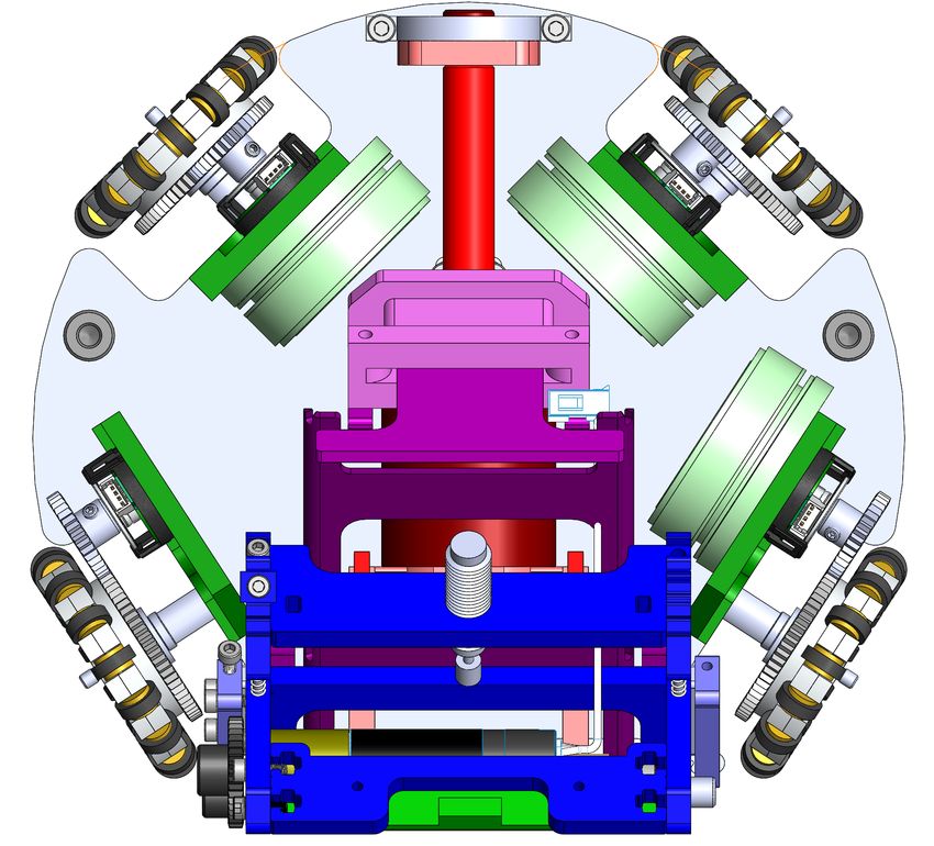
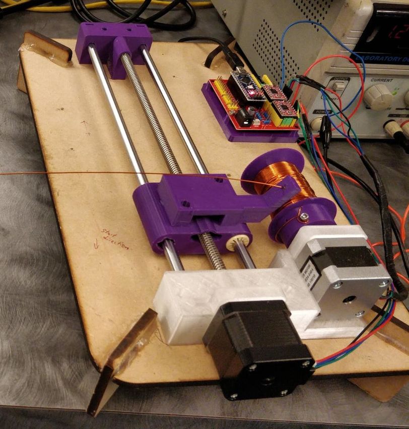
2     Mechanical

In order to continue to remain competitive within the SSL league it was identified
that the mechanical structure of our current fleet of robots would need to be
redesigned. Much of the mechanics of our robots have remained the same since
2011, and the majority of those parts had not been re-machined since then.
Due to wear on the robots, they have become increasingly more difficult to
maintain. Not only have our robots experienced significant damage, but much
of the original design is complicated and difficult to manufacture.
In the past the team has experienced trouble implementing new mechanical de-
signs due to the restricted constraints provided by the other mechanical systems
in place. This made it nearly impossible to implement mechanical improvements
the team felt necessary to increase quality of game play. This year we have de-
cided to design and manufacture a new fleet of robots to alleviate this issue. The
primary focus of the mechanical designs were to increase precision of movement,
catchment and play of the ball. The designs have taken ease of manufacturing
and reputability heavily in mind. The following is a description of our current
design progress to date.

2.1   Chipper/Kicker
Our goal this year was to completely redesign the chipper mechanism to take
up less space and work in tandem with a rotating kicker. Since the kicker had
not been finalized there was not many constraints to begin with, we began by
designing two different concepts for a compact chipper.
The first design was a chipper that was actuated beneath the kicker (orange
component in figure 2.1) and between a disjointed rotating platform. This is done
by rotating the rear Geneva gear segment to turn the kicker that pivots around
a raised point above the chipper. A proof of concept simplified CAD model was
developed to test the mechanics and relative sizes of the components.
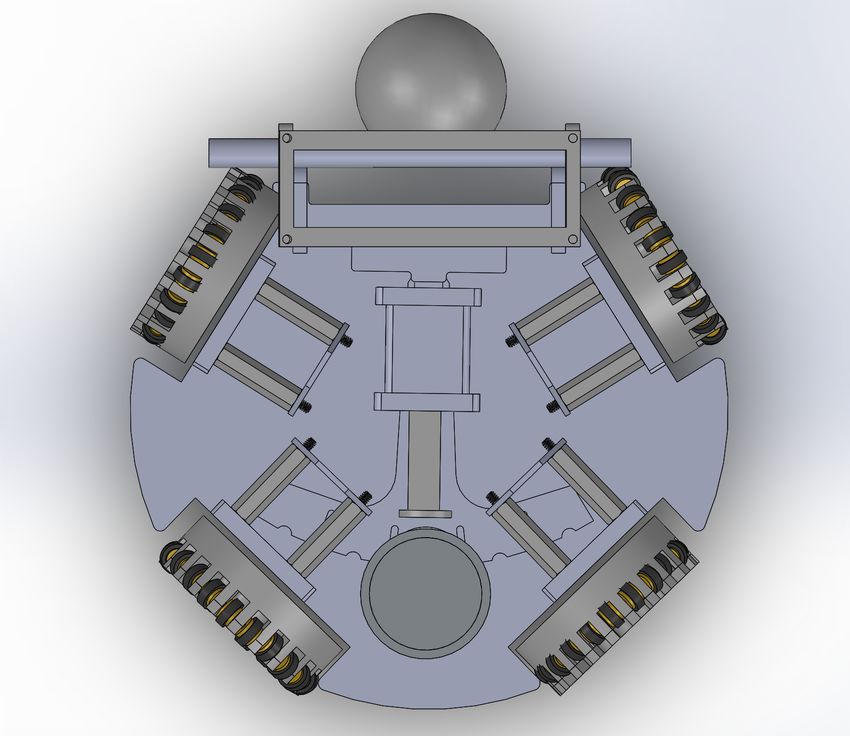
Fig. 2.1: CAD Model of New Chipper Design

This model proved the viability of a disjointed rotating platform using a separate
pivot point that was bridged to the rotating platform with the kicker mechanism.
This allowed us to use the space below the kicker for the chipper without the
chipper being affected by the rotation.
Unfortunately, the design was rejected due to limited space below where the
kicker shaft needed to be placed. After considering the size of the ball we realized
the chipper and solenoid would have to fit in a just a 4mm space below the kicker,
which is was not viable due to the size of the solenoid.
This led us to design a secondary concept where the chipper solenoid was
mounted to the mid plate of the robot (it is mounted to the bottom plate in the
figure below for ease of prototyping). The chipper would then be an L shaped
component that when pulled horizontally by the solenoid would flick the chipper
plate up contacting the ball at a 45◦ angle.
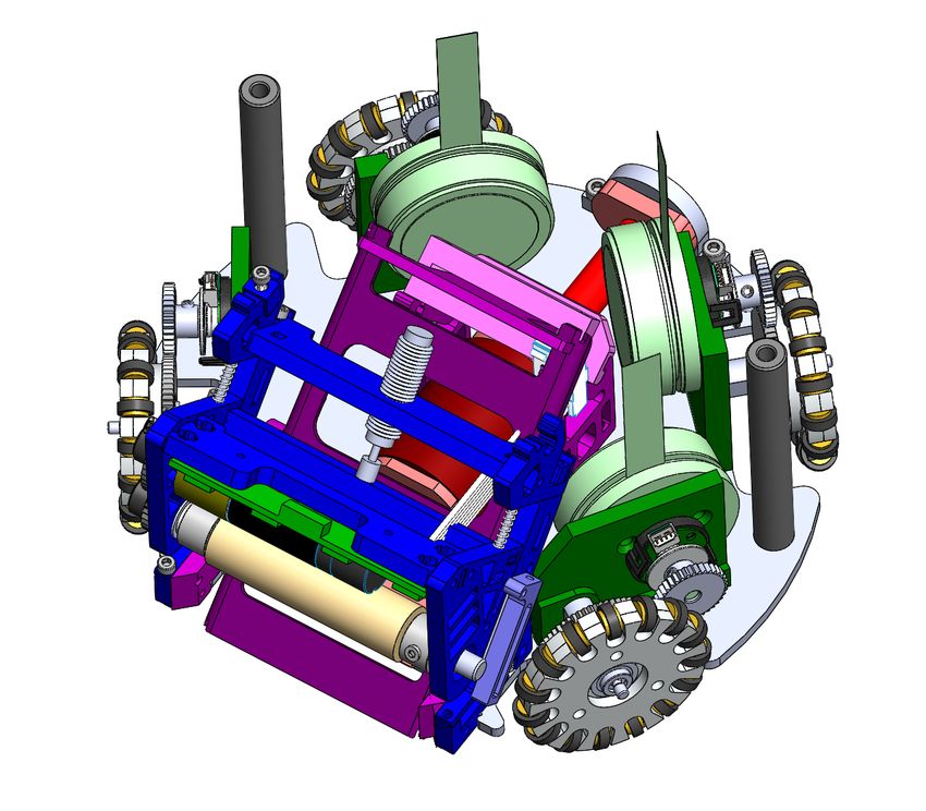
Fig. 2.2: Simplified CAD Model of New Chipper/Kicker Design

Our proposed chipper component utilizes parametric design principles to enable
efficient re-dimensioning in the future. This design, therefore, allows for future
changes to our space constraints without requiring a full redesign. This was done
partly to to simplify re-dimensioning, however more importantly for adjusting
the force transfer from the solenoid to the ball. A partner script was written that
took an input of the same variables used in the dimensions of the chipper and
the input force from the solenoid. The output of the script was the force that
the chipper arm impacts onto the ball.
Multiple combinations of design parameters were tested to see the relationship
between the dimensions of the arm and the force transfer. We found that the
most important influences were the lengths of the arm segments, and the travel
distance of the plunger through the solenoid. However small changes in these
dimensions did not make an appreciable difference in the force transfer.
Using this data we decided on an initial set of prototype dimensions for the
chipper.

2.2   Rotating Kicker
With the current fixed kicker, our robots are limited to linear kicking and passing.
Incorporating a rotating kicker would allow for angled passing and shooting
during a game reducing the predictability of kick direction. The current design
iteration of our rotating kicker can be seen below in figure 2.3 which takes
inspiration from Op Amps 2017 TDP and builds off our Geneva drive design
from last year [1]. We chose the Geneva drive designed last year because of the
simple but effective design that allows easy electrical integration. A geared DC
motor rotates a wheel with a pin which contacts the slot on the edge of the
rotating plate, thus rotating the plate along the base-plate of the robot. Based
on the general assumption the kicker and solenoid will have a mass of 300g, the
torque required to rotate the plate was measured to be around 130 mNm. The
rotating plate will be optimized to rotate a set number of degrees with each
motor shaft revolution. With this current design the available kicking angles are
6.9 and 13.8 degrees, however this may be changed in future iterations after
testing.
A proof-of-concept prototype was developed consisting of 3D printed parts and
a motor driving circuit confirmed the feasibility of the design. Currently, we are
changing part dimensions to ensure everything fits properly within the robot.
Further testing with materials and comprehensive robot prototypes will need
to be completed to ensure parts can withstand applied stresses and work well
dimensionally and functionally with the kicking and shipping systems of the
robot.

                        Fig. 2.3: Rotating Kicker Design

The motor selected for the Geneva drive is a 30:1 geared 24V DC motor. The
motor is capable of supplying about 134 mNm of torque, which was found to be
sufficient based on conservative estimates for the Geneva drive.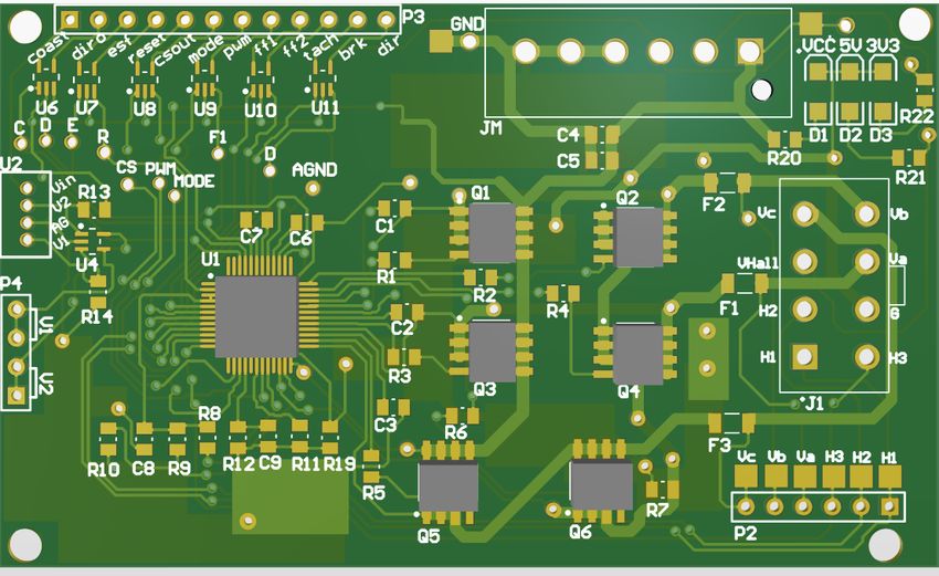
The absolute position of the kicker must be known at all times to ensure correct
positioning during game-play. To satisfy this condition, we have researched vari-
ous encoders that may be suitable for this application. The motor selected comes
with an optional encoder that fits on top of the motor to track the position of
the shaft. These encoders however only give us relative position of the kicker.
Because the absolute position must be known, the system must be calibrated
upon start-up. Options currently being investigated: Hall-effect sensors or abso-
lute position encoders, which are all feasible solutions to the position tracking
challenge.
With this design, the robot will achieve angled kicking and therefore gaining a
strategic advantage over other teams. It may also be capable of curved shots by
kicking at an angle while the ball is being spun by the dribbler, thus increasing
strategic play and allowing the team to execute more advance strategies.

2.3   Wheels
The goal of the new wheels is to increase the accuracy of the robot’s movement,
which was affected by the smoothness of the old wheels, and save space by
enabling an internal ring gear design. To increase the rolling smoothness the new
wheels are larger with a diameter of 55mm compared to 47mm of the old wheels.
The increase in size was done to accommodate 21 brass bushings surrounding the
wheel, an increase from the previous wheel’s 15. The new transmission should
decrease the amount of carpet buildup in the gears, a problem experienced in
previous years. The reduction in overall depth of the drive-train is necessary, as
the upgrade to thicker 50 watt motors would conflict with the chipper and kicker
systems.
Three versions of the new wheel were created. The first design was a wheel that
kept the current size of 47mm with 18 brass bushings. The second iteration was
the 55mm wheel with 21 bushings and a third double stacked wheel, consisting
of two current wheels stuck together. All three wheels had internal gearing im-
plemented, and 3D prototypes of each were built for testing. The 55mm wheel
with 21 bushings had the best compromise between smoothness and packaging
constraints, so it was selected to be the final design for the new wheels. The
final design will use metal gears and the wheel body will be machined out of
aluminum.
The new wheels provide increased smoothness allowing the robot to be more pre-
cise in its movements. The added smoothness of the new wheels was immediately
noticed during testing.
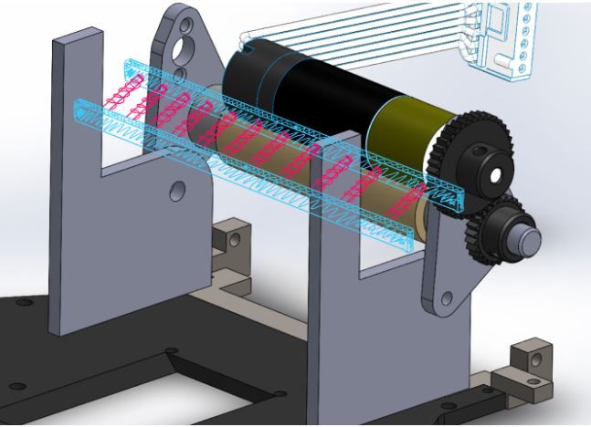
Fig. 2.4: New Wheel Design

2.4   Dribbler

        Fig. 2.5: Preliminary Dribbler Design with Rotation Damping

We are currently still in the preliminary design stages, but we have concepts
which we hope to resolve our current issues with. These include the follow-
ing:
 – Our old dribbler frame uses lots of steel which causes our robots to be very
   heavy at the front, thus hindering mobility
 – The large amount of small, metal parts in the dribbler frame makes our
   dribbler difficult to assemble and maintain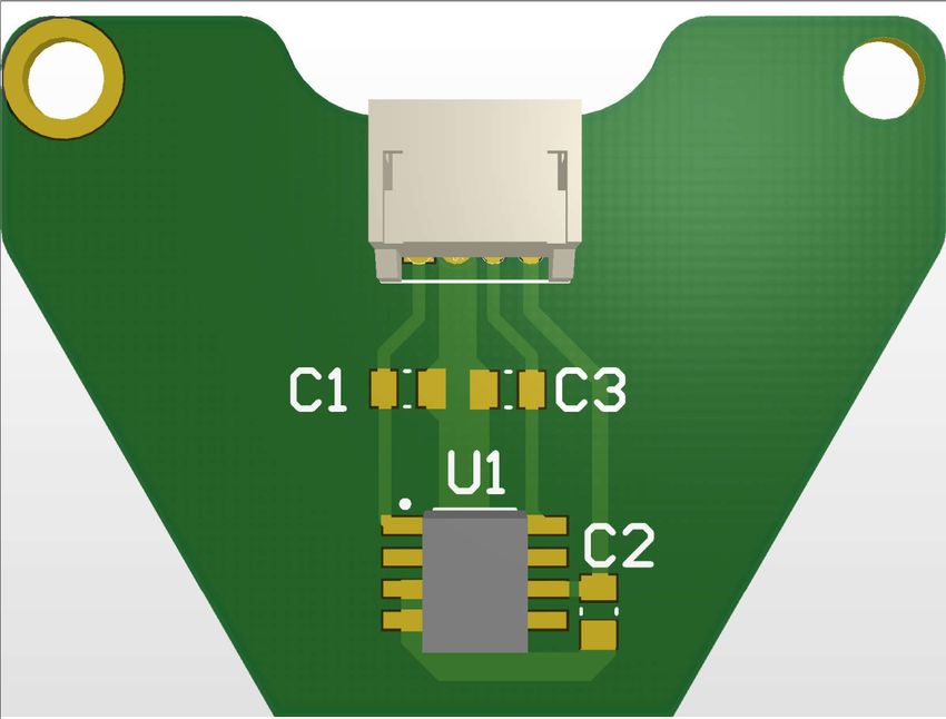
– Our old damping mechanism experiences friction and weight that tends to
   inhibit damping
In our new design, we aim to create a mechanism that is simple, lightweight,
and compact so that the robot can be easily assembled and maintained as well
as provide improved weight distribution. We will also aim to create a damping
mechanism that minimizes any forces that go against the dribbler’s damping
motion, namely frictional and gravitational forces.
To reduce excess weight and friction that goes against damping and ball move-
ment, we considered a design which utilizes rotational damping as opposed to
linear damping. By minimizing the amount of moving material when damping
occurs, there will be less weight and friction to resist damping which would allow
our robots to more efficiently catch the ball. This will also allow us to also con-
sider a 3-point touch model (inspired by ZJUNlict’s 2019 design) to increase ball
control, where we would motivate the ball to maintain contact with the ground,
dribbler, and chipper at all times. In doing this, we use friction to our advantage.
Since the chipper has less friction than both the carpet and the dribbler bar, the
ball would oscillate on a minuscule scale between the carpet and the dribbler
bar using the chipper as a pivot point.
An initial design that is currently being tested in our first physical prototype of
the new robots can be seen in figure (b). This design is simple by using minimal
parts, while still providing effective damping, while also taking up less space. A
comparison from the old design (a) can be seen in the figures below.

           (a) Current Dribbler            (b) Dribbler Design for First Revision

                    Fig. 2.6: Comparison of dribbler designs

With our new design this year, we hope to maximize ball control in so as to
maintain Thunderbots’ competitiveness among the SSL teams. With increased
ball control we hope that our robot may be able to enhance performance, not
only in terms of ball control, but in terms of kicking, chipping, and general
maneuvering.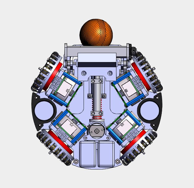
2.5 Design Summary
Overall our design focuses have changed significantly since the last generation
of robots. With the increases in field size and ever-improving opponents, speed
and agility became a large focus for improvement. Our drivetrain was a primary
focus of our design, around which other components were fit. Overall the new
robots are significantly more space efficient and use simpler components for easier
manufacturing and assembly, both of which are important should we choose to
scale this fleet to compete in Division A.
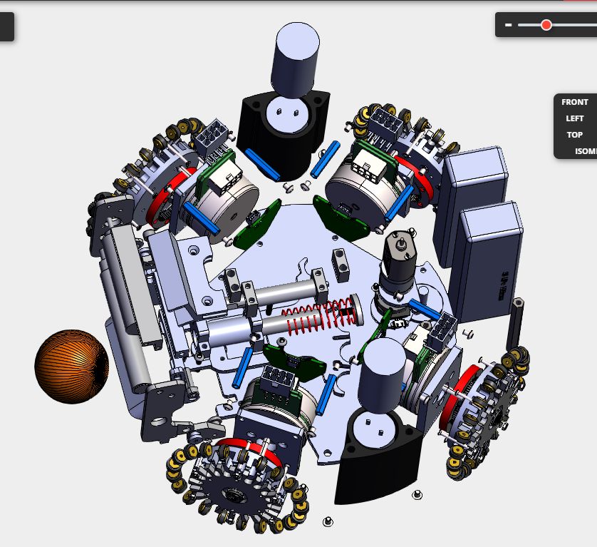
(a) Old CAD Assembly (b) New CAD Assembly
(a) Old CAD Assembly (b) New CAD Assembly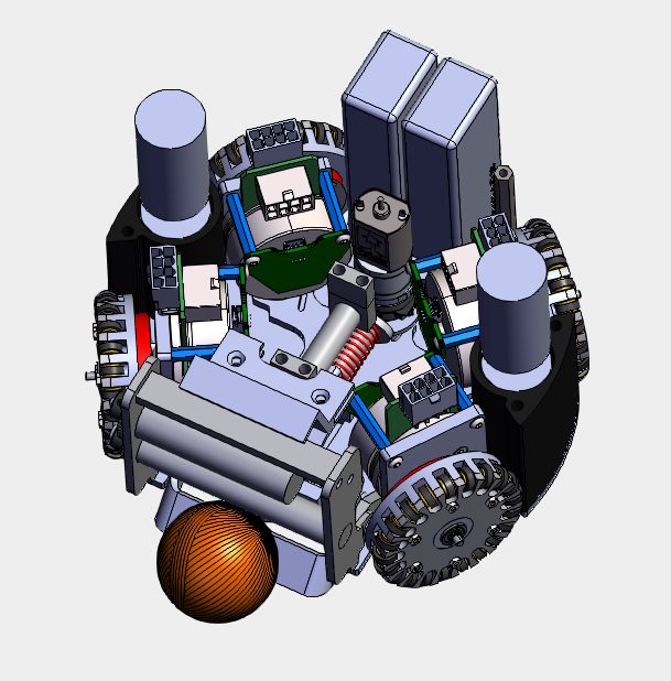
Fig. 2.9: Exploded view of the new CAD assembly
3      Electrical
3.1     Electrical System Redesign
It has been several years since a major hardware revision has been done. Al-
though our legacy system functions, the overall architecture is outdated and
this has placed major limitations on the software team. Furthermore, the time
required for repairs has been increasing exponentially as the years of wear and
tear have taken their toll. So, we set the goal this year of creating a new system
for RoboCup 2020 and have been progressing since then with the goals of robust-
ness and preparing for future needs. The following is an outline of the electrical
changes between the legacy and new systems.

    Legacy
    Main board             Power distribution, main MCU + FPGA, motor driver,
                           RF, motion control
    Chicker board          HV DC/DC conversion, solenoid driver
    Breakout board         Connects to motor and encoders
    Encoder                Optical encoder (note: externally sourced)
    Wheel motors           Maxon EC 45 flat 30W
    New
    Control board           Main MCU, motion control, WiFi & Motor driver board
    Power and Chicker board Power distribution, HV DC/DC conversion, solenoid
                            driver
    Encoder board           Magnetic encoder (custom PCB, made in house)
    Wheel motors            Maxon EC 45 flat 50W
          Table 3.1: Comparison of the legacy and new electrical systems

3.2     Power and Chicker Board
In the legacy system, the chicker board (boost converter and chipper and kicker
solenoid driver) was placed at the very top of the system, which led to a large
distance between the solenoids and the board. Further, the chicker board had to
be connected to the legacy main board as the main board housed the entire power
distribution system. Although convenient for testing the motors and the LV
system, the integrity of the significantly more expensive main board was put at
risk if the chicker board were to malfunction while testing. On several occasions,
a capacitor blowing caused an entire set of robot PCBs to be damaged.

Power Distribution Improvements
 – Reverse polarity protection
 – Power monitoring IC
Fig. 3.1: New System Architecture – 5V/3A DC/DC conversion for LV system power The legacy design had limited circuit protection and power analytics and so the main goal of improvements to the power distribution system has been to improve on those fronts. This was accomplished by integrating a custom reverse polarity protection circuit and a power monitoring IC (Texas Instruments INA226 [2]). Further, to allow for the additional loads in future revision, e.g. sensors and measurement devices, the legacy 5V/1.5A integrated DC/DC converter which was used to regulate the battery voltage for the LV system was replaced with an asynchronous buck converter configured for a 5V/3A output (controlled by the Texas Instruments TPS54331 [3]). Major Legacy Chicker Drawbacks The legacy Chicker board consisted of a boost converter, capacitor bank, and solenoid driver circuit. Ultimately, the lack of circuit protection, isolation, and a robust feedback system along with the mechanical placement and structural shortcomings of the PCB led to significant problems throughout its use. If the solenoid driver IGBTs latched open, the battery would be short-circuited, which could deliver more than 60A. Such a high current inrush has destroyed power traces in both the main board and chicker board, broken expensive ICs, and burned some of the insulation. The gate latching can be caused by either a malfunction in the gate or faulty connections to the control signals. Due to the inadequate PCB structure, the center of gravity of the Chicker board was at the back edge, pulling control pins out of the female receptacle on the main board. Furthermore, very large capacitors are required to appropriately smooth the
output waveforms, without which damaging voltage spikes during switching can
occur. In recent years, the number of capacitors has been reduced for mechanical
reasons, which increased the magnitude of the spiking.

Chicker Improvements
 – Topology switch from a boost converter to a non-isolated DC/DC converter
 – Flyback controller IC with built-in under/over-voltage detection
To remedy the many issues in the legacy design, the LT3751 [4], a flyback con-
troller designed for high-speed capacitor charging, will be used along with a
non-galvanically isolated flyback converter. Although no galvanic isolation will
be present, the transformer ensures that no direction connection back to the
source exists, and allows the controller to protect against fault conditions [5].
This choice of IC was based on the designs of the Mannheim Tigers [?] and
the Georgia Tech RoboJackets [6]. By using an IC dedicated to our application,
the overall performance, efficiency, and robustness of the chicker system will be
greatly improved. Further, real-time systems, such as DC/DC converters, benefit
from the concurrency of ASICs. Designing efficient and robust power converters
is a highly involved process, and we as a team recommend that newer teams
employ the use of similar ICs.
A closing note, the SEPIC topology was also considered, but requires larger
magnetics compared to the flyback topology. SEPIC converters are typically
more efficient (92% vs 88%), the financial and space cost of larger magnetics,
along with the increased complexity of the control system motivated the choice
of using a flyback converter [7].

3.3   Control Board
Our legacy control board previously contained all of the low voltage components
such as our microcontroller, FPGA, radio, and motor drivers. This was conve-
nient for manufacturing and assembly but made it difficult to debug and repair
boards after incidents because of how many components were on the PCB. One
of the biggest changes we made for the control boards was first of all breaking out
all the motor driver circuitry onto a separate PCB. This allowed us to test each
hardware revision with widely available development boards. Another change
we made was changing from a microcontroller (STM32F4) and FPGA (Spartan-
6 family) combination to a high performance microcontroller (STM32H7). The
high performance STM32H7 chip will provide room for more intensive on-board
computation in the future. This change was also motivated by the reduction in
cost and in PCB space.
However, the removal of the FPGA came at a cost. In the legacy system, each
of the four wheel and single dribbler BLDC motors were driven by a set of three
half-bridge drivers controlled by the FPGA, requiring fifteen phases of PWM to
be generated. We addressed this issue by integrating a three-phase gate driver
which essentially eliminated the need for the FPGA (Allegro A3931).
The FPGA also dealt with deserializing the radio packets. In the new system,
we are shifting to a 5GHz WiFi module that communicates via SPI or via built
in Ethernet core in the ARM MCU.
With the combination of peripheral ICs, we have significantly simplified the
control board. Further, the removal of the FPGA reduced the complexity of
our code base, decreased our technical debt, improved member engagement in
firmware development, and improved our ability to both debug and maintain
firmware.

3.4   50W Wheel Motors

      (a) Old: Maxon EC 45 flat 30W         (b) New: Maxon EC 45 flat 50W

                     Fig. 3.2: Old and New Wheel Motors
As mentioned in table 3.1, the new system will see the integration to 50W BLDC
motors. The shift from 30W to 50W presents multiple challenges related to the
power distribution, motor driving, and overall motion control. The following
is a comparison of the key characteristics of both the legacy and new wheel
motors:

                                    EC45 flat 30W   EC45 flat 50W
            MF, MP                  Maxon, 200142   Maxon, 251601
            Ratings at the Nominal Voltage
            Nominal Voltage         12V             24V
            No load speed           4360 rpm        6710 rpm
            Nominal speed           2910rpm         5240 rpm
            Max. continuous torque 54.9 mNm         83.4 mNm
            Max. continuous current 2.02A           2.33A
            Stall torque            247 mNm         780 mNm
            Characteristics
            Torque constant         25.5 mNm/A      33.5 mNm/A
            Speed constant          374 rpm/V       285 rpm/V
            Speed/torque gradient 18.2 rpm/mNm      8.77 rpm/mNm
  Table 3.2: Comparison of the legacy (30W) and new (50W) wheel motors
The main changes are related to the supply requirements and the motion control.
With a double in nominal voltage and an increase in nominal current, the power
distribution system needed to be redesigned. And although it is beneficial to have
increased continuous torque, allowing for quicker stops and higher acceleration,
the movements become jerky and greater care must be taken to facilitate smooth
movement. This helped motivate the shift to a PID controller from the legacy
hysteresis controller.
3.5 Motor Driver PCB
As mentioned in the control board section, the removal of the FPGA was fa-
cilitated by the integration of three-phase BLDC motor driver IC: the Allegro
A3931. This driver allows a BLDC motor to be controlled with a single PWM
signal, instead generating three phases of PWM. It also includes support for Hall
sensor feedback for EC, further reducing the processing load for the main con-
troller. This driver features several additional inputs, including coast (turning
all FETs off without affecting any control logic), brake (turning off the low side
FETs and turning on the high side), and mode (switching the high side only vs
switching low and high sides). The choice of the motor driver was inspired by
the Mannheim Tigers [8] and ZJUNlict [9]. The addition of this motor driver
has reduced the overall complexity of our electrical system and allow more pre-
cise control over our robots’ movements. Further, the redesign facilitated the
integration of 50W motors: a step up from the previously 30W motors.
The legacy control board housed numerous modules, including all gate drivers
and FETs. As a means to reduce overall repair costs, the motor drivers will be
modular and connect into the main board via board-to-board latch-lock connec-
tors. Further, this will allow for more flexibility of design and simpler hardware
revisions (e.g. 70W motors).
Fig. 3.3: Motor Driver Board PCB, revision 2
Figure 3.3 shows the second revision of the motor board. The layout is bloated
for testing purposes and will be compressed in the final revision.3.6 Breakbeam
Fig. 3.4: Types Of Photoelectric Sensors [10]
The legacy system featured a through-beam photoelectric sensor. Although cost
effective and fast responding, the mechanical fixture for the LED and photo-
transistor pair proved to be insufficient. The parts would slide in their holders.
Further, the holder became deformed over years of collisions which caused beam
misalignment and misreadings.
On the electrical side, we investigated many options for a new breakbeam, re-
searching the benefits and drawbacks of implementing mirrors, lasers, ultrasonic
devices, etc. In late 2019, we were considering a Time of Flight (ToF) sensor,
which measures the distance to an object based on the amount of time it takes
for emitted photons to be reflected back. We tested multiple ToF sensors, but
found that the increased cost, complexity, and latency of the sensors rendered it
unfeasible for the application.
Following the ToF sensor tests, we returned our focus to through-beam and
reflective (specifically retro-reflective) photoelectric sensors. While they do not
have large angle variance tolerances, through testing we concluded this limitation
will not significantly affect the sensor performance in our application.
We are also currently testing different infrared LED and IR optical sensor combi-
nations to create our own breakbeam. This includes creating both retroreflective
and through-beam breakbeam setups.
For testing the LEDS and optical sensors, we are measuring the effective dis-
tances they can communicate, and thus ’break the beam’, on a flat 2D grid. The
optical sensor is secured at the axis, while the corresponding LED is moved in x
and y directions and the allowable distances are recorded in a spreadsheet.We have tested both 3mm and 5mm IR LEDs and concluded that the smaller di-
ameter increases intensity while also decreasing chances of misalignment. There-
fore, we will be focusing our testing on 3mm or smaller LEDs.
The table below shows the current options. Testing is still underway.
Component Name Comments
Optek Technology OPB732 Reflective, phototransistor output
Silicon Labs SI1102 Logic output, configurable distance
Kingbright WP710A10SF4BT-P22 Infrared (IR) Emitter 880nm
Wurth Elektronik 15400585A3590 850nm Infrared LED
Vishay TSSP94038 Optical Sensor IR 940nm
Melexis MLX75305KXD-AAA-000-RE Optical Sensor Ambient 850nm
Lumex Inc. OED-EL-1L2 Infrared (IR) Emitter 940nm
Table 3.3: Current Top Breakbeam Sensor Options
3.7 Magnetic Encoder
The decision to switch to magnetic encoders is based on previous failures of opti-
cal encoder due to debris (primarily from the competition field turf). A magnetic
encoder measures the angle of an external field using an arrangement of magneto-
resistive elements. They are robust against light impeding contaminants along
with environmental factors such as vibration and shock; their higher inherent
reliability also ease manufacturing/assembly, increasing tolerances while remov-
ing the need to build environmental protection into the sensor assembly. These
advantages enable significantly lower cost while providing similar or greater res-
olutions compared to optical counterparts.
The TLE5501 or TLE5009 from Infineon Technologies are interchangeable on-
shaft sensors whom were selected for their low cost. They output two sinusoidal
signals with a relative offset of 90 degrees which can resolve angular position
over 360 degrees with a diametrically polarized magnet, see figure 3.5.
Although the sin/cos waveforms increase the overall complexity of rotational
motion encoding in comparison to incremental rotary encoders, it allows flexi-
bility in the resolution as it is dependent on the resolution and sampling rate of
the microcontroller’s ADCs. This is facilitated by the shift to an STM32H7(60
ADC channels, 16-bit, max 3.6MSPS) [11] from the STM32F4(57 ADC chan-
nels, 12-bit, max 2.4MSPS) [12]. Further testing and development of calibration
methods are required for fully functional integration.Fig. 3.5: Nominal output signals versus rotational angle of the TLE5009 from
Infineon’s datasheet [13]
Fig. 3.6: Encoder PCB
3.8 WiFi
Over the past few years it has become apparent that we are pushing against
the bandwidth capacities of our current radio chip; the MRF24J40. With only
600 kbit/s of bandwidth, we have been forced into being more and more creative
with both the data that we send to the robots, and how we pack that data. With
the leagues push towards larger teams, coupled with a general interest in WiFi
from both teams and the league, it was decided that a switch to 5GHz WiFi
was the sensible option. We are at present testing three separate potential WiFi
systems, the details of which may be found in the table below.Options Benefits Drawbacks
Fully independent MCU a firmware stack,
highly programmable
Redpine Signals No standard software
Rs14100 interface, protocols
Numerous hardware interfaces
must be designed
Operated by sending AT
Communication occurs over SPI via data
Inventek Breakout boards not
ISM43362 offered
Chip signals over GPIO trigger when there is
data available to be polled [14]
Communicates directly with the network stack
of the STM32H7 via RMII
Allows us to use the same network stack and
logic for both wired and wireless
UBlox ODIN- Breakout boards not
W262-06B U-connect software provides AT interface and offered
web interface for easy configuration
Intelligent memory management using Ethernet
DMA buffers built into HAL
Table 3.4: Current Top WiFi Options
3.9 Solenoid Design Tool
With major changes to the mechanical structure, the space for solenoids that
actuate kicking and chipping has been decreased. To optimize the force output
given the space restrictions, the existing solenoid and plunger force models have
been revamped to allow for more design options along with an updated GUI. The
new model attempts to simplify the process of altering specific dimensions and
material selections to optimize the solenoid and plunger systems while adhering
to spacing requirements. Previously, the dependency on electrical characteristics
created a barrier for the mechanical team when it came to the solenoid design.
The new tool integrates more electrical assumptions, and mostly relates me-
chanical and material parameters of the solenoid and plunger combination to
the output force. This drastically decreased the knowledge barrier, so will be
used for designing our solenoids from now on.
We will make the solenoid design tool along with an accompanying paper publicly
available as a means to lower the knowledge barrier for new SSL teams.
3.10 Solenoid Winder
The solenoids are manufactured in house, which was previously completely man-
ual. This created poor consistency across the robot fleet due to inconsistentnumbers of turns in each solenoid along with varying turn density (number of
turn layers in a given area). In the past, we had an automated solenoid winder
based on an Arduino with a motor shield, a small RC-type servo for position
control and a stepper motor for rotation. There were significant difficulties with
this design resulting from inadequate control over the positioning of the wire
meaning that it was not really usable for production of solenoids.
This year, we built a new solenoid winder with the goal of better and more accu-
rate control over the wire while winding. Our solenoid winder uses two stepper
motors, one with an integrated lead screw for lateral control over the wire, and
one for rotational control over the core being wound. We used an Arduino-based
control board designed for a laser cutter and 3D printer parts in the winder itself
to significantly reduce the cost of the manufactured components.
Fig. 3.7: Custom Solenoid Winder
The CAD, code, and setup instructions for the solenoid winder can be found
at https://github.com/UBC-Thunderbots/Solenoid-Winder. We hope that
in providing this design guide, our team can continue to lower the barrier for
new teams and teams with limited financial resources.4 Firmware / Control
All firmware is open-source, and is available from our git repository: https:
//github.com/UBC-Thunderbots/Software.
4.1 Strict Application/IO Division
The previous design of our firmware architecture had no strict distinction be-
tween higher level sections, such as the controller and primitive action implemen-
tations, and lower level operations, like driving the wheels via PWM or storing
logs to the SD card via the onboard FPGA. This had lead to a complete lack
of portability, and has made the code much more difficult to understand by
consistently side-stepping any existing abstractions. With the new generation of
robots, and the desire to integrate much of firmware into our simulator, it became
very clear that we would need a clear division between portable (Application)
code and non-portable (IO) code.
Application code is any code that may be run on any of our hardware or sim-
ulated platforms, in essence everything down to and including applying wheel
force, turning the dribbler, or querying the current robot position/orientation/velocity.
IO code is everything below application code, such as actually driving the wheels
via PWM, actuating the kicker, or getting new world information via a network
stack. This split is enforced by the creation of structs of functions such as apply-
WheelForce or getRobotPosition which are passed to the application layer, and
act as its sole interface to the outside world. This makes it trivial to replace
the “outside world” with either a different hardware architecture or simulated
environment, both of which we have done this year.
Fig. 4.1: Application / IO Separation
This more general firmware architecture has the potential to be very useful
for new teams looking to get started in the SSL. It provides an interface for
controlling robots, agnostic of any hardware, and allows higher-level firmware
logic and control to be developed more quickly. In particular, new teams would be
able to start working on firmware control and higher-level code without requiring
physical hardware to be ready immediately.Furthermore this architecture makes simulation significantly easier. Accurate
simulation of physical robots and firmware behaviour has traditionally been a
challenge for the SSL. This architecture is a step toward firmware that is more
portable into various simulation systems. As mentioned above, different struct
functions can be implemented using a team’s simulator of choice and then pro-
vided to the application layer of the firmware. This allows for relatively easy
integration of robot firmware into a team’s simulation.
4.2 Improved Controller Design
This year we are aiming to completely redesign our motion control. Our current
design is a bang-bang controller that has limited close-loop control and minimal
attention to physical limitations of the robots dynamics [15]. To facilitate better
overall control this year, we are developing a state-space based controller for
the robot to replace our current bang-bang controller. This controller will use
principles based on CNC machine control.
1. Trajectory Planner - The Trajectory planner will be responsible for deter-
mining valid paths that our robots can physically follow, and breaking the
paths down into constant-time intervals that will be sent to the controller.
2. Controller - The controller is responsible for breaking the constant-time
segments sent by the Trajectory planner into reference signals sent to the
robots wheels. The controller will be PID Pole Placement to allow for robot
physical parameters to be incorporated into the controller and simplify tun-
ing.
Fig. 4.2: Control and Trajectory Planning StructurePreviously we would generate a trajectory in Software without any explicit check for whether or not the path was physically possible. With our new controller design, we will be able to check all generated trajectories against the on-robot controller in high-level software for before they are passed to the robot. This provides us with guarantees about the feasibility of our generated trajectories, while simultaneously allowing us to execute even more aggressive maneuvers. These improvements will allow us to execute high-level strategy quicker and more accurately, indirectly improving all aspects of our gameplay. One application of this new control scheme is the ability to accurately intercept a moving ball. Having an accurate model of the robot dynamics will allow us to evaluate these dynamic problems instead of basing some of our control on zero final velocity paths. These improvements are beneficial to the league as our modular segregation of the motion control elements can be used by new and existing teams, like we have seen in the past with our open-source software and firmware. 5 Software In pursuit of the league’s goal of progressing multi-agent coordination and con- trol, the software team has prioritized (1) simulation to enable repeatable testing of complex plays and (2) motion planning and control to execute those plays as efficiently as possible. We address the limitations of our current simulator by im- plementing a new one and we are pursuing a motion planner that better accounts for robot dynamics. All firmware is open-source, and is available from our git repository: https: //github.com/UBC-Thunderbots/Software. 5.1 Path Planning To fully utilize our new control scheme described in section 4.2, we are develop- ing a new path planning system whereby a series of trajectories are generated in the form of time-parameterized splines. Each spline begins at the current robot location and ends at the target location, with the start and end tangents indicat- ing the initial and final direction of travel. The use of splines allows us to enforce n-th order continuity on the trajectories, which directly translates to smoother robot movement through the discontinuous profiles of of jerk, acceleration, etc.. These splines are then passed through the controller that will eventually run them on the robot, allowing us to check that they are feasible and violate no physical constraints. This provides us with a guarantee that our generated tra- jectories can be reasonably executed on the robots. It has been noted that there is some time between trajectory generation and execution, however this is small enough (
In the event that feasible spline cannot be found, we have still managed to
improve upon our previous path planner (RRT) [16], via the implementation of
the Theta* algorithm. Theta* is a refined version of A* that implicitly smooths
paths, finding the path that best minimizes the number of changes in direction
and total path length [17]. It uses the Euclidean distance to the objective to
prefer exploring paths in the graph that get closer to the objective. Compared
to A*, Theta* is more likely to find the shortest possible path. Compared to RRT,
Theta* is deterministic, which makes it easier to test and debug. Furthermore,
it provides the strict guarantee that it will find a path to the goal (if one exists)
under the condition that the heuristic used is admissible (we use the euclidean
distance).
We have also improved upon our collision avoidance system by using the veloc-
ities of other robots to predict where they might be and avoid those areas. We
call these “Velocity Obstacles”. By inflating obstacles in the direction of their
velocity the path planners will adjust to avoid a moving obstacle much sooner,
whereas without the Velocity Obstacles the path planners would adjust too late
and our robot’s momentum would carry it into a collision. These changes are
critical to helping us avoid incurring fouls and penalties for high-speed collisions
with other robots.

              Fig. 5.1: Planning Around a Robot Velocity Obstacle
5.2 Full-Stack Continuous Validation Via Simulation A large part of this team’s success over the past year was due to careful validation of our software stack at multiple levels, and the automation of that validation to reduce the burden on team members. One significant exception to this was our inability to design robust automated tests for our entire system, in particular our Plays from the STP architecture [18]. This limitation arose from the fact that full stack tests rely upon having a method for mocking both outputs and inputs to the system while being flexible enough to validate expected behavior at a high level, rather than just an exact set of outputs. The obvious mechanism for providing this sort of feedback is a simulator, but our current simulator, GrSim, is both physically inaccurate and non-deterministic. Furthermore, the velocity commands sent to GrSim are too high level to allow us to test our firmware, an essential part of our stack. As such, the decision was made to develop our own simulator. This would allow us the ability to give determinism guarantees, tightly control test scenario generation and validation, and test the behavior of a significant amount of our firmware stack. The simulator is based off Box2D, a 2D physics engine. A 2D engine was se- lected both for simplicity and computational efficiency. 3D physics engines were considered but ultimately disregarded, as the vast majority of robustly testable behavior occurs in 2D, with chipping being the one exception; in this case we have implemented a simple parabolic trajectory and disabled collisions for the duration of the flight. The other 2D physics engine that were considered was Chipmunk2D. While Box2D and Chipmunk2D are very similar, we chose Box2D due to its slightly more accessible documentation and popularity within the community. Abstractions were developed around this physics engine up to the level of our firmware application-layer API, as detailed in section 4.1. This allowed our firmware to directly control robot motion in the simulator. An API was developed to allow direct control over every aspect of the simulator, from the game state to the individual robot capabilities, allowing for the creation of specific and repeatable scenarios. We have further developed a set of libraries for test creation, based around the concepts of timelines and global assertions. A timeline is a time-variant sequence of constraints that we wish to check over the duration of a test, such as a sequence of behaviors for a particular robot, or a series of interactions between robots and the ball. A global assertion is a time-invariant constraint or set of constraints that we wish to enforce for the duration of the test. This could be as simple as “the ball may not exceed some speed”, but can rapidly scale and compose to form models of the entire rulebook and beyond. The combination of these two concepts allow for the flexible creation of tests spanning the entire gamut of possible behaviors, and the tight coupling of our simulator and AI allows us to enforce all of these constraints over the world at each point in time.
Fig. 5.2: Full-Stack Simulation Architecture

Due the modular design of our software, we were able to simply replace the com-
ponents that handled publishing vision information and accepting robot primi-
tives in order for the simulation to work our AI and the rest of the system [16].
This allowed us to make use of our existing AI Visualization tool to view and
control the simulation.

       Fig. 5.3: A Simulated Defense Scenario Shown in Our Visualizer

This simulated full-stack testing enables us to develop gameplay logic and strat-
egy much quicker. Because it is able to simulate firmware logic, it removes the
dependency on robot hardware to make firmware and control changes. It also
allows us to test much larger-scale strategies because we are not constrained by
the space of our physical testing field.
Furthermore, having tests for our high-level gameplay logic enables us to make changes much more quickly, and with significantly more confidence. At previous RoboCups we ran into many issues where certain changes led to unintended con- sequences that we didn’t realize until our next game, where we would either need to tolerate them or use a timeout to fix them. Being able to run a test suite that validates all our gameplay logic behaves as expected will allow us to have more confidence in our changes and prevent our gameplay from regressing. 6 Conclusion We believe that the design changes detailed above will lead to significant im- provements in performance. We look forward to putting the changes into action at RoboCup 2020. 7 Acknowledgements We would like to thank our sponsors, as well as the University of British Columbia, specifically, the Faculty of Applied Science and departments of Mechanical Engi- neering, Engineering Physics, and Electrical and Computer Engineering. With- out their continued support, developing our robots and competing at RoboCup would not be possible.
References
 1. T. Yoshimoto, T. Horii, S. Mizutani, Y. Iwauchi, Y. Yamada, K. Baba, and S. Zenji,
    “OP-AmP 2017 Team Discription Paper,” 2017.
 2. “INA226 High-Side or Low-Side Measurement, Bi-Directional Current and Power
    Monitor with I2C Compatible Interface.” http://www.ti.com/lit/ds/symlink/
    ina226.pdf.
 3. “TPS54331 3-A, 28-V Input, Step Down DC-DC Converter With Eco-mode.” http:
    //www.ti.com/lit/ds/symlink/tps54331.pdf.
 4. “LT3751 - High Voltage Capacitor Charger Controller with Regulation .”
    https://www.analog.com/media/en/technical-documentation/data-sheets/
    LT3751.pdf.
 5. R. Kollman, “Power tip 62: Boost or flyback for extreme conversion ratios?,” August
    2013.
 6. G. I. of Technology RoboJackets, “kicker-3.2,” 2019.
 7. J. Betten and R. Kollman, “Power supply topology: SEPIC vs Flyback,”
 8. A. Ryll, M. Geiger, C. Carstensen, and N. Ommer, “Extended Team Description
    for RoboCup 2018,” 2018.
 9. ZJUNlict, “Main board,” 2019.
10. “Photoelectric      Sensors.”      http://www.ia.omron.com/support/guide/43/
    introduction.html.
11. “STM32H7         ADC        speed.”      https://community.st.com/s/question/
    0D50X00009XkaQfSAJ/stm32h7-adc-speed.
12. “stm32f4 adc max sample rate.” https://community.st.com/s/question/
    0D50X00009XkXcn/stm32f4-adc-max-sample-rate.
13. “TLE5009 Datasheet.” https://www.infineon.com/dgdl/Infineon-TLE5009_
    FDS-DS-v01_01-en.pdf?fileId=db3a304330f686060131421d8ddd56b0.
14. J. Almagro, C. Avidano, C. Lindbeck, J. Neiger, Z. Olkin, E. Peterson, K. Sta-
    chowicz, W. Stuckey, M. White, M. Woodward, and G. P. Burdell, “RoboJackets
    2019 Team Description Paper,” 2019.
15. J. Fraser, S. Ghosh, C. Head, S. Holdjik, N. Jaques, A. Lam, B. Wang, A. Wong,
    and K. Yu, “2014 Team Description Paper: UBC Thunderbots,” 2014.
16. S. Churchley, R. De Iaco, J. Fraser, S. Ghosh, C. Head, S. Holdjik, N. Ivanov,
    S. Johnson, F. Kalla, A. Lam, B. Long, K. Lu, S. Ng, K. Peri, J. Petrie, E. Roach,
    W. Y. Su, B. Wang, C. Xi, K. Yu, and K. Zhang, “2015 Team Description Paper:
    UBC Thunderbots,” 2015.
17. A. Nash, “Theta*: Any-angle path planning for smoother trajectories in continuous
    environments,” September 2010.
18. B. Browning, J. Bruce, and M. Veloso, “Stp: Skills, tactics, and plays for multi-robot
    control in adversarial environments,” Proceedings of the Institution of Mechanical
    Engineers, Part I: Journal of Systems and Control Engineering, vol. 219, no. 1,
    p. 33–52, 2006.
You can also read