2021 Direct Injection Technical Specifications - OWNERS Product - PERFORMANCE TO MOVE YOU - PCM Engines
←
→
Page content transcription
If your browser does not render page correctly, please read the page content below
2021 Direct Injection
   OWNERS Product
Technical Specifications

 PERFORMANCE TO MOVE YOU
                           05/20
                           06/20
                                1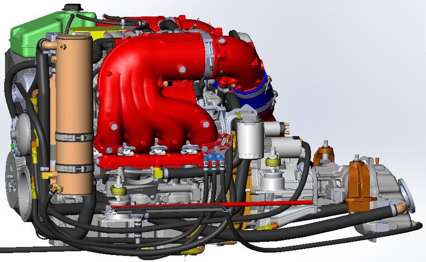
Warranty
                                                                         PCM 5 YEAR / 1000 HOUR TRANSFERABLE LIMITED WARRANTY
Pleasurecraft Marine Engine Co., through its PCM Engines Division (“PCM”), warrants its new products to be free from defects in material and workmanship under normal use and service conditions. This
warranty is extended only to the first registered owner or registered user, as well as all subsequent users who comply with PCM’s warranty transfer policy and receive PCM’s approval of warranty transfer.
The obligation of PCM under this warranty shall be limited to the repair or replacement with new or reconditioned components, at PCM’s option, of any product, or parts thereof, which have failed during the
warranty coverage period specified below and are demonstrated upon examination to have failed due to defective material and/or workmanship.
WARRANTY COVERAGE; TRANSFER; WARRANTY PERIOD
This warranty is extended to the first registered owner or registered user purchasing the engine at retail, as well as all subsequent users who, in accordance with PCM’s warranty transfer policy and warranty
transfer approval, must notify PCM within 30 days of any subsequent sale of the product at which time PCM will review for an approval of the transfer of any remaining portion of warranty coverage. To
obtain a PCM Warranty Transfer Application, contact your local Pleasurecraft dealer or PCM’s Warranty Services Department at (803) 345-1337. Certification of an inspection of the product by an
authorized technician and payment of a warranty transfer fee are required to be submitted with the Application.
All components, other than those itemized below and those components that are warranted by PCM’s suppliers, are warranted, solely for non-commercial use, for a period of 5 years or 1,000 hours of use,
whichever first occurs, from the earlier of (1) the date of sale to the first registered owner or registered user, or (2) from the date the engine is first placed into service for demonstration or any other purpose
prior to the sale of the engine to the first owner purchasing the engine at retail. Commercial use is defined as, but not limited to, use of the product by ski schools, for promotional use, for athletes’ boats, for
rentals, etc. In the case of commercial use of the product, the term of this warranty shall be for a period of 5 years or 1,000 hours of use, whichever occurs first, from the earlier of (1) the date in which the
engine is first registered, or (2) within 30 days from the date the boat was manufactured.
Components not covered under this warranty:
(1) Water pump impellers are not covered by this warranty.
(2)	Seals, gaskets, O-rings, and other materials affected by time are not covered by this warranty if their effectiveness is reduced by an extended storage period prior to sale or use of the product.
(3) Items such as, but not limited to, lubricants, spark plugs and other items which are frequently replaced as part of routine maintenance.
NO OTHER WARRANTY GIVEN
The obligations set forth in the preceding paragraphs are PCM’s sole obligation and the owner’s exclusive remedy. PCM makes no other express warranty. Any implied warranty of merchantability or
fitness for a particular purpose that may be applicable to this product is limited in duration to the duration of this warranty. Some States do not allow limitations on how long an implied warranty lasts, so the
above limitation may not apply to you.
No distributor, dealer, agent or employee of PCM is authorized to grant any other or further warranty or incur any additional warranty obligation on PCM’s behalf in connection with the sale of its products.
Any qualification or restriction contained herein which is prohibited by any law of mandatory application shall be deemed to be deleted from this warranty; however, such deletion shall have no effect on the
remaining provisions hereof, all of which shall remain in full force and effect.
REMEDIES
The obligation of PCM set forth in the first paragraph of this warranty shall be the exclusive remedy for any breach of warranty hereunder, and any owner or user’s sole remedy in the event of breach
of the warranty is repair or replacement of the product or any warranted part thereof as set forth in this warranty. With this sole exception, PCM shall not be liable for any direct or indirect, incidental or
consequential damages, including without limitation, any damages for property damage, loss of use or loss of profits, loss of income, inconvenience, trailering, towing, haul out, launch and/or any other in
and out of water expenses, storage charges, dockage charges, expenses to deliver or pick up the product being warranted to and from the dealer, telephone expenses, lodging expenses, travel expenses,
mechanic travel time and mileage, damage caused by any occurrence of an insurable nature, rental of substitute equipment of any type, removal and replacement and/or modification of any boat parts to
facilitate repairs, moving of furniture, carpets, cleaning, painting, carpenter work, or re-delivery charges. Some States do not allow the exclusion or limitation of incidental or consequential damages, so the
above limitation or exclusion may not apply to you.
Any owner or user hereby waives for himself/herself/itself and his/her/its successor and assigns (a) any and all claims for punitive damages, and (b) all claims of negligence or strict liability or both. In no
event will PCM’s liability exceed the purchase price of the product(s) which is actually paid to PCM.
OBTAINING PERFORMANCE UNDER WARRANTY
PCM’s warranty registration form should be prepared by your selling dealer, executed by you and the dealer, and mailed by you to PCM within 30 days after the date of your purchase of the product. Upon
receipt of the warranty registration form, PCM will issue to you a personalized owner’s registration card which will be mailed directly to you. If the owner’s registration card is not received within 8 weeks after
the date of purchase, please write to PCM at the address set forth below.
At the time that a claim for warranty service is made, the owner’s registration card should be presented to the person or entity providing warranty service. Authorized PCM dealers or distributors are entitled
to be reimbursed by PCM for some or all of the expense of warranty repairs; thus, service under the terms of this warranty will be performed by an authorized PCM dealer or distributor without charge for
established flat rate labor or replacement parts, other than items not covered by the warranty, such as, but not limited to, water pump impellers, seals, gaskets, O-rings and other materials affected by time
if their effectiveness is reduced by an extended storage period prior to sale or use of the product, and lubricants, spark plugs and other items which are frequently replaced as part of routine maintenance.
Charges for additional non-warranty work and/or additional dealer charges for labor relative to warranty work in excess of flat rate must be paid for by the owner.
Prior authorization in writing must be obtained from PCM for any warranty repairs over $50.00 and in all cases where the owner fails to establish the purchase and warranty expiration dates with the owner’s
registration card sent upon receipt of the warranty registration form by PCM. While failure to present the owner’s registration card will not prevent you from obtaining coverage hereunder, this warranty shall
not be effective and, therefore, cannot be honored until the product purchase date can be confirmed by PCM. If the card is lost, communicate with PCM at the address listed below, and, for a processing fee
of $10.00, a new owner’s registration card will be issued to you.
Any questions concerning service, parts or this warranty should be directed to your selling dealer. If your dealer is unable to assist or if you relocate, if you are traveling or if you need a referral to your
nearest dealer, contact: Pleasurecraft Marine Engine Co., 1737 Highway 76, Little Mountain, SC 29075 (803) 345-1337.
FAILURES EXCLUDED FROM WARRANTY
This warranty will not apply to any failure which results from accidents, sinking, fire, neglect, abuse or abnormal service or use, such as racing, towing or operation in water of insufficient depth, or to
any failure resulting from improper installation, improper adjustments, repairs or improper delivery service, or to any failure resulting from the use of parts, fuels, oils or lubricants not suitable for use with
the product and/or materials or parts not approved by PCM. This warranty does not apply to any engine or drive which has been modified, or altered, or repaired in such a manner as, in the opinion of
PCM, to affect its stability, reliability or performance. Further, this warranty will not apply to product failure resulting from (1) use of non-recommended lubricants or fuels, (2) failure to follow maintenance
or lubrication schedules, (3) failure caused or contributed to by improper or contaminated fuel, (4) failure caused by water intrusion, salt corrosion to external components, or improper installation or
misapplication of the engine or drive, (5) the owner’s or operator’s failure to exercise due or normal care and precaution, (6) failure of components and/or assemblies that are warranted by PCM suppliers,
and (7) damage resulting from the owner’s or operator’s failure to timely replace failed water pump impellers, seals, gaskets and O-rings.
OWNER’S RESPONSIBILITY
Performance under this warranty shall be conditioned upon the first registered owner’s or registered user’s compliance with the following requirements:
(1)	Owner or user shall verify that the pre-delivery service has been performed, all requested information recorded and that the selling dealer has signed the warranty registration.
(2) Owner or user shall promptly mail the warranty registration to PCM after accepting delivery.
(3) Owner or user shall follow the instructions in the owner’s manual regarding operation, break-in, lubrication and fuel.
(4)	Owner or user shall follow or comply with the maintenance schedule, operation limits, and lay up instruction, as outlined in the owner’s manual. Pleasurecraft original equipment genuine marine
        engine parts should be used whenever service or repairs are performed.
CHOICE OF LAW
This limited warranty shall be governed by, and construed and interpreted in accordance with, the local laws of the State of Ohio (without application of its conflicts of laws principles), except only to the
extent replaced or precluded by other law of mandatory application.
GENERAL
This warranty gives you specific legal rights, and you may also have other rights which vary from State to State.
The PCM Federal/California Emissions Warranty and Federal/California Emissions Control Warranty Statement are separate documents included in the owner’s manual. Any questions concerning the
Emissions Warranty can be obtained by calling PCM at (803) 345-1337.
PCM’s policy is one of continued improvement of its products, and PCM hereby reserves the right to improve and change the design and production of any of its products without assuming any obligation to
modify products previously manufactured and/or sold.

2
Warranty

                                         PCM WARRANTY TRANSFER APPLICATION
The remainder of the warranty coverage period of the original Pleasurecraft (“PCM”) limited warranty is transferable within thirty (30) days of date
of sale by the original owner/user to a subsequent purchaser for the remainder of the unused portion of the original warranty coverage period, or
the remainder of 1,000 hours of use, whichever first occurs. The original date of sale or original in-service date (whichever comes first) begins
the warranty coverage period. For commercial use such as, but not limited to, use of the product by ski schools, for promotional use, for athletes’
boats, for rentals, etc., the warranty coverage period starts from the earlier of (1) the date in which the engine is first registered, or (2) within 30
days from the date the boat was manufactured.

Direct Sale by Authorized Pleasurecraft Marine Dealer:
If the sale is conducted through an authorized Pleasurecraft Marine dealer, the dealer must complete and submit the PCM Warranty Transfer
Application, the required engine photographs, Diacom recording and warranty transfer fee. The warranty transfer application will be processed
based on the approval of PCM. This inspection will be at the seller or purchaser’s expense.
Sale by Private Individual / Non-Authorized Dealer:
If the sale is conducted between private individuals, or between a private individual and an unauthorized Pleasurecraft Marine dealer, the
engine/drivetrain must be inspected by an authorized Pleasurecraft Marine dealer. This inspection will be at the seller or purchaser’s expense.
The dealer must complete and submit the Warranty Transfer Application, the required engine photographs, Diacom recording and warranty
transfer fee. The warranty transfer will be processed based on the approval of PCM.
The fee for warranty transfer is $400. The transfer fee (via certified check) and Warranty Transfer Application must be submitted to PCM within 30
days of date of sale to:
                                Pleasurecraft Engine Group
                                1737 Highway76
                                Little Mountain, S.C., 29075
• The new owner will be notified within 10 days of PCM’s receipt of the Warranty Transfer Application form regarding whether the transfer has
  been approved by PCM. If the transfer is approved, the warranty expiration date will be provided.
• A Warranty Registration Card will be issued to the second owner, reflecting the change has been made in PCM’s computer.
OUTSIDE THE U.S. AND CANADA, CONTACT YOUR LOCAL PLEASURECRAFT DEALER OR PCM WARRANTY SERVICES AT
(803) 345-1337 FOR MORE INFORMATION ON HOW TO APPLY FOR A WARRANTY TRANSFER.
IMPORTANT! PURCHASER NOTICE: The inspection below is designed to insure safety and satisfaction. Therefore, we require the following
inspection to be performed at your expense, by an authorized Pleasurecraft technician, prior to purchase. By signing below, the technician
certifies that he/she has checked the installation and operation of the engine and finds it to be performing properly. All terms in the Limited
Warranty located in the Engine Owner’s Manual still apply.
ENGINE MODEL:                                                            ENGINE SERIAL:
TRANS. SERIAL:                                                           ENGINE HOURS:
HULL SERIAL #:                                                           BOAT MANUFACTURED DATE:
INSPECTION DATE:
Warranty Transfer Inspection
        Check for Bulletins                                    Trouble Codes Checked                          Belt and Pulley: Inspect for Damage
                                                               Trouble Codes Cleared
        Engine Oil: Check                                      All Fuel Lines: Confirm No Leaks               Exhaust Hoses/Clamps: Inspect
        VDrive Lube: Check                                     All Oil Lines: Confirm No Leaks                Record Propeller Size and Rotation
                                                                                                              Diameter______Pitch______Rotation ______
        Transmission Fluid: Check                              All Water Lines: Confirm No Leaks              Engine Compression
                                                                                                              Cylinder 1 ______ Cylinder 2 ______
        Propshaft Alignment
                                                               All Drain Plugs: Confirm                       Cylinder 3 ______ Cylinder 4 ______
        Battery Rating, Charge, and                            Proper Installation                            Cylinder 5 ______ Cylinder 6 ______
        Level: Check                                                                                          Cylinder 7 ______ Cylinder 8 ______
        Diacom Recording:                                      (3) Engine Photos:
        Ignition ON, Engine OFF Recording                        Include engine top, port and starboard (photos must be clear and in good light)
        (submit with application)
I hereby certify the warranty transfer inspection on engine S/N __________ and have corrected any abnormality revealed by this inspection.

(Technician signature, Dealer & Date)         (Seller’s Signature and Date)                        (Purchaser’s Signature and Date)

DATE OF SALE (2ND Owner) _____/_____/_____                               DATE OF SALE (1st Owner/1st Operator) _____/_____/_____
(New Owner)                                                              (Previous Owner)
NAME:                                                                    NAME:
ADDRESS:                                                                 ADDRESS:
CITY, STATE, ZIP:                                                        CITY, STATE, ZIP:
EMAIL ADDRESS:
   By checking this box, you are authorizing PCM to send the email address to receive emails whenever a product bulletin or safety recall affects this
product.

                                                                                                                                                           3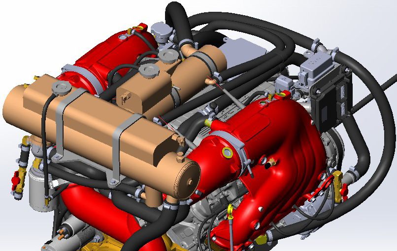
Warranty
                                 Engine Serial Number and Specification Decal Locations

                                                                                                                                 PLEASURECRAFT
                                                                                   MODEL 30-04-E01                                ENGINE GROUP
                                                                                     RATIO               SERIAL NO.              POWER PLUS
                                                                                    1:1     3128
                                                                                                                         RATIO      1.48
                                                                                   Pleasure Craft Engine Group                      16672
                                                                                             MADE IN U.S.A.                       MADE IN USA

           1. ENGINE SPECIFICATION DECAL      2. ENGINE IDENTIFICATION DECAL    3. TRANSMISSION                       4. VDRIVE
                                                                                IDENTIFICATION PLATE                  IDENTIFICATION PLATE

                 ENGINE RPM CHART
		                Minimum                                                      IMPORTANT
 Model            Full Load       Preferred      Maximum                       Your new Pleasurecraft Marine engine incorporates an
                                                                               RPM “MAX GOVERNOR” in order to prevent the engine
                                                                               from over-revving. Operation above the Maximum RPM is
    5.3L DI          5300           5500            5600
                                                                               not recommended. If your engine is operating above the
                                                                               maximum RPM listed, a higher pitched propeller would be
    6.2L DI          5300           5500            5600                       required to lower the engine maximum RPM to the Preferred
                                                                               RPM.
    6.2L DI SC       5100           5200            5300

                                                                                   CAUTION
                                                                               Prolonged WOT operation will shorten the life of your engine
                                                                               and could cause premature engine failure. Problems caused
                                                                               by prolonged WOT operation are considered abuse and are
                                                                               not covered under the Pleasurecraft Marine Warranty.

4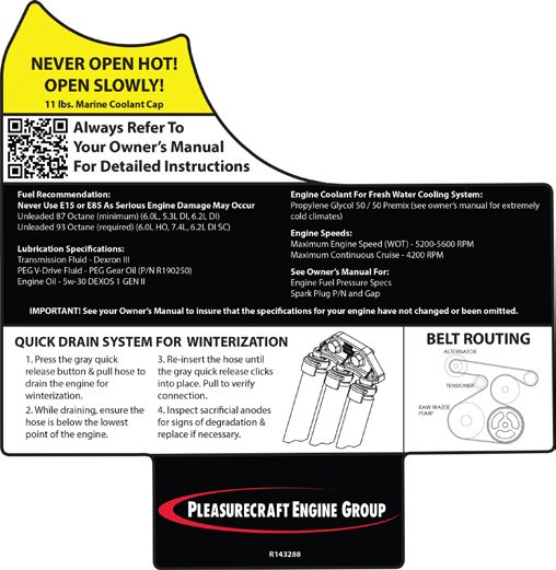
Engine and Transmission Fluid Capacities
                                                    ENGINE FLUID CAPACITIES
                                    Model                                         ALL MODELS

                                    Crankcase Oil Capacity
                                    W / NEW FILTER                      Start with 6 Quarts (5.7 Liters)1

                                    Fresh Water Cooling
                                    System Capacity                      Fill Until Completely Purged3

                       		                                                    Oil Requirements
                        Engine                                               All Temperatures
                       5.3L DI / 6.2L DI / 7.4L                          Dexos 1 / Gen 2 5W-30
                               6.2L DI SC                                              0W-40
These engines require the use of SAE 5W-30 DEXOS GEN 2 formula oil. These engines must be serviced with this weight and formula engine
oil.
These engines are designed specifically with use of DEXOS GEN 2 formula engine oil. This formulation is now found in most major brands of
engine oil.

WARRANTY NOTICE: PCM Engines reserves the right to refuse warranty on part(s) and/or engine(s) damaged by using improper fuels and
engine oils.

Engine Oil and Oil Filter Change Intervals
    •	Initial oil change - 1st 60 days or 25 hours of operation, whichever occurs first
    •	Regular oil changes - Every 50 hours of operation or 120 days, whichever occurs first
    •	Heavy Duty High RPM / High Load Use - Every 30 hours of operation or 120 days, whichever occurs first
NOTE: Never over-fill the engine with oil. Engines over-filled with oil can cause engine damage.

                                              TRANSMISSION FLUID CAPACITIES
  Model                                                                           All Models                                   Type

  PCM, 1:1 Ratio 1,2                                                           2.0 Quarts (1.9L)                           DEXRON III

  PCM, 1.23:1 Ratio 1,2                                                        2.0 Quarts (1.9L)                           DEXRON III
			                                                                                                                  PowerPlus V-Drive
			                                                                                                                       Lubricant
Pleasurecraft V-Drive, All Ratios 1,2 1.5 Quarts (1.42L)                                                          Pleasurecraft Marine P/N -
			                                                                                                                       R190251

        1-E   ngine Fluid Capacities are dependent on installation angle. DO NOT overfill the crankcase or transmission. Remove excess
            fluid above the “FULL” mark on the dipstick. Check oil with the boat at its normal, level, at rest position on the water. Ensure that
            ballast systems (if equipped) and excess water in the bilge have been purged. If the boat is on a trailer, the trailer must be level and
            adjusted to represent the boat’s normal resting state on the water. Oil capacities are approximate, and may not include capacity
            needed for transmission cooler and oil lines. Refer to the Checking Fluid Levels instructions and Changing Oils instructions
            of this manual, for complete instructions, important notes and Cautions for checking engine oil levels. Always use the dipstick to
            determine the exact quantity of oil required. Add the correct amount of oil to fill to the “FULL” mark on the oil level dipstick.
        2 - IMPORTANT: 80 Series PCM 1:1, 1.23:1 and all other transmission fluid levels are checked at operating temperature and
            immediately after shutdown of the engine.
        3 - Fresh Water Cooling systems vary depending on half-systems, full-fresh systems, heaters, hose lengths, etc. System should be
            completely purged of air and the coolant level should be within the MIN/MAX level of the degas bottle after the engine has been ran
            at operating temperature and the system is allowed t to cool down overnight. Top off as necessary.

                                                                                                                                                  5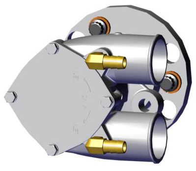
Specifications

                                     MASTER ENGINE SPECIFICATIONS
 MODEL                             5.3L DI                         6.2L DI                       6.2L DI SC
		                                  CES                             CES                             CES

    Displacement               5.3L (327 CID)                   6.2L (378 CID)                  6.2L (378 CID)

    Bore                     3.78 in. (96.01 mm)             4.06 in. (103.25 mm)            4.06 in. (103.25 mm)

    Stroke                    3.62 in. (92.0 mm)              3.62 in. (92.0 mm)              3.62 in. (92.0 mm)

    Compression Ratio               11:1                            11.5:1                          9.1:1

    Compression                 130 - 215 psi                    130 - 215 psi                   130 - 215 psi

    WOT Operating RPM            5300-5600                       5300 - 5600                     5100 - 5300
    Preferred WOT RPM              5500                             5500                            5200

    Cruising RPM (Max)              4480                            4480                            4240

    Idle RPM (In Gear)         Not Adjustable                   Not Adjustable                  Not Adjustable

    Oil Pressure @               25 - 60 psi                     25 - 60 psi                     25 - 60 psi
    2000 RPM                   (172 - 414 kPa)                 (172 - 414 kPa)                 (172 - 414 kPa)

    Minimum                  5 psi (35 kPa) - Idle           5 psi (35 kPa) - Idle           5 psi (35 kPa) - Idle
    Oil Pressure         24 psi (165 kPa) - 4000 RPM     24 psi (165 kPa) - 4000 RPM     24 psi (165 kPa) - 4000 RPM

    Spark Plug P/N                R030013                         R030013                         R030014
    Spark Plug Gap                0.040 in.                       0.040 in.                       0.040 in.

    Firing Order               1-8-7-2-6-5-4-3                 1-8-7-2-6-5-4-3                 1-8-7-2-6-5-4-3

    Thermostat                170° F (76.6° C)                 170° F (76.6° C)                180° F (82.2° C)

    Over- Temperature         210° F (93.3° C)                 210° F (93.3° C)                210° F (93.3° C)

    Exhaust Cooling      240°F (115° C) - Stage 1      240°F (115° C) - Stage 1        240°F (115° C) - Stage 1
    System Over-         250°F (121° C) - Stage 2      250°F (121° C) - Stage 2        250°F (121° C) - Stage 2
    Temperature              Engine Derates                Engine Derates		                Engine Derates

 Electrical System           12 Volt Negative (-)            12 Volt Negative (-)            12 Volt Negative (-)
		                                Ground                          Ground                          Ground

    Alternator Rating             150 Amps                        150 Amps                        150 Amps

 Battery Rating              650 CCA (Minimum)               650 CCA (Minimum)               650 CCA (Minimum)
		                                120 Ah                          120 Ah                          120 Ah

       NOTE: FOR NEW BOAT PROPPING, IT IS RECOMMENDED THAT OEMS PROP TO THE MAXIMUM RPM LISTED.

6
Specifications
LH ROTATION
FRONT
1 2
3 4
5 6
7 8
NO
DISTRIBUTOR
FLYWHEEL END OF ENGINE
ALL V-8 MODELS
FIRING ORDER:
1-8-7-2-6-5-4-3
PCM FUEL PRESSURE and ALARM WARNING SPECIFICATIONS
MODEL ALL NOTES
FCC Fuel Pressure 57-62 psi @ WOT Monitored with sensor and displayed on
Diacom Diagnostic Tool.
Fuel Rail Operating Pressure 580 psi - 2100 psi Monitored with sensor and displayed on
Diacom Diagnostic Tool.
Fuel Pressure - LPFP 7 - 9 psi
ALL ENGINES (WOT)
Coolant Over Temperature 210°F / 215°F Causes engine to go into Power Derate.
DTC 116 / 117
MIL and Buzzer
Engine Derates
Exhaust Manifold Water 240°F / 250°F Causes engine to go into Power Derate.
Temperature Sensors DTC 1415 / 1416 /
(Fresh Water Applications) 1417 / 1418
MIL and Buzzer
Engine Derates
Low Engine Oil Pressure < 5 psi @ idle / Causes engine to go into Power Derate.
< 35 psi @ 4000 (Stage 1)
< 30 psi @ 4000 (Stage 2)
DTC 524 / 520
MIL and Buzzer
Engine Derates
Closed Loop Control DTC 1155 / 1156 Causes engine to go into Power Derate.
Out of Range DTC 1157 / 1158
Adaptive Fuel Control DTC 171 / 172 Causes engine to go into Power Derate.
Out of Range DTC 174 / 175
IMPORTANT: FUEL PRESSURE VALIDATION MUST BE MADE WITH THE ENGINE UNDER LOAD.
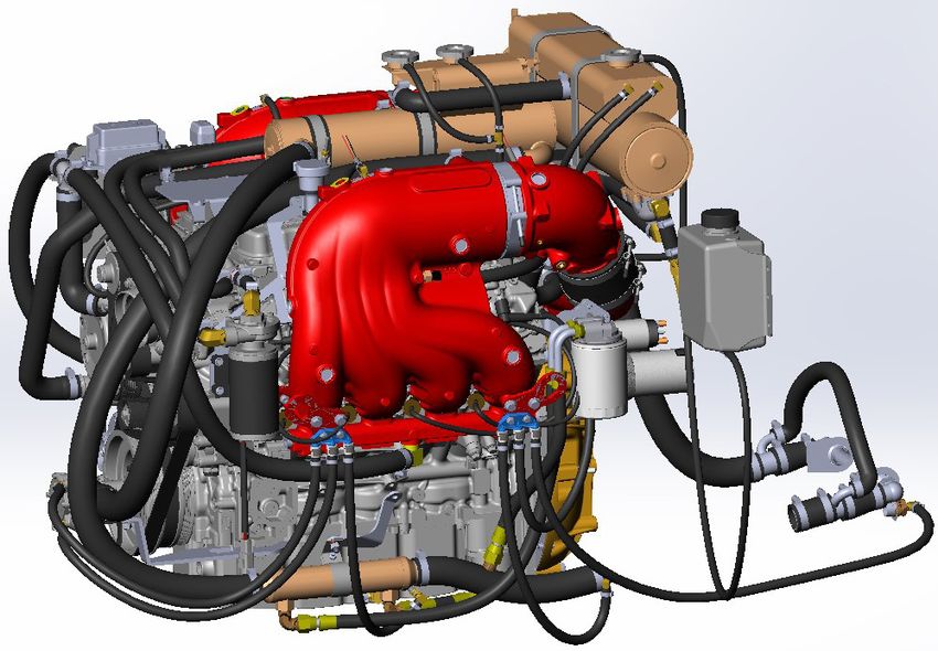
7Accessory Drive System
ACCESSORY DRIVE BELT
PCM engines use a single serpentine belt to drive the
engine water circulation pump, sea-water pump and the
alternator.
WARNING
Engine must be shut OFF and the ignition key removed
before inspecting the drive belt(s). The drive belt(s)
should be checked periodically for condition and
tension. If the belt(s) shows signs of cracking, glazing
or deterioration, replace with new belt(s).
DRIVE BELT INSPECTION
Inspect the drive belt for excessive wear, shredding or
missing sections.
Inspect the drive belt for contamination from excessive
dirt, oil, coolant or other substances that may effect the Accessory Drive Belt Configuration
drive belt operation.
If a problem is found, replace the belt after inspecting the
DRIVE BELT REPLACEMENTS (6.2L DI SC)
following items:
• All pulleys and tensioners for signs of
Accessory Drive Belt Part Number: R066044
misalignment Supercharge Drive Belt Part Number: R066043
• All pulleys and tensioners for signs of rust or 1. Note the routing of the belt before removing.
other damage 2. Using a 1/2” drive ratchet, turn the belt tensioner
• Bent pulleys or tight bearings in the engine water to relieve the tension on the belt. Slide the belt
circulation pump, sea-water pump and alternator off of the pulleys. Release the tensioner slowly
to prevent the tensioner from snapping
DRIVE BELT REPLACEMENT (5.3L/6.2L DI) against its stop, and possibly causing
Part Number: R066042 damage to the tensioner.
1. Note the routing of the belt before removing. 3. Slide the new belt onto the pulleys using the
same routing as noted prior to removal.
2. Using a 1/2” drive ratchet, turn the belt tensioner
to relieve the tension on the belt. Slide the belt 4. Compress the belt tensioner, and slide the belt
off of the pulleys. Release the tensioner slowly over the tensioner pulley. Release the tension
to prevent the tensioner from snapping slowly to tension the belt.
against its stop, and possibly causing
damage to the tensioner.
3. Slide the new belt onto the pulleys using the
same routing as noted prior to removal.
4. Compress the belt tensioner, and slide the belt
over the tensioner pulley. Release the tension
slowly to tension the belt.
8Accessory Drive System
SERVICING RAW WATER PUMP IMPELLER SERVICING RAW WATER PUMP IMPELLER
(Modular Raw Water Pumps) (6.2L DI SC Raw Water Pumps)
IMPELLER KIT #: RP061022 IMPELLER KIT #: RP061023
The raw water pump impeller should be serviced every The raw water pump impeller should be serviced every
50 hours, or once a year, whichever occurs first. See 50 hours, or once a year, whichever occurs first. See
Maintenance Schedule. Maintenance Schedule.
Locations “A” are access holes in order to loosen the raw IMPORTANT: The raw water pump does not have to be
water pump attaching bolts. The bolts are secured in the removed from the engine to service the impeller.
pump by O-rings, and will not fall out during removal. 1. Remove the (4) retaining bolts from the pump
Torque the raw water pump housing attaching bolts front cover. Remove the pump cover.
to 8.5-9 ft.lbs. (11.5-12 N-M), when re-installing the 2. Discard old O-Ring.
impeller.
3. Using two flat head screwdrivers, work the
impeller out of the pump body.
NOTE: This pump uses a key way. Make sure the key is
secure in place.
Raw Water
4. Install the new impeller into the pump body
Pump ensuring the key fits in properly.
5. Install the new O-ring and pump cover.
6. Tighten the retaining bolts securely.
A
Raw Water Pump Impeller Bolt Locations “A”
9Cooling System Raw Water Drain Locations
5.3L DI / 6.2L DI
QUICK DRAIN SYSTEM FOR WINTERIZATION
1. Press the gray quick release button & pull the hoses to drain the
engine for winterization.
NOTE: ALL three drain hoses must be disconnected while draining to
ensure the system drains completely.
2. While draining, ensure the hoses are below the lowest point of the
engine. Hoses should not be reconnected until summerization.
3. Inspect sacrificial anodes for signs of degradation & replace if
necessary.
4. Inspect the blue drain block to ensure ALL O-Rings are in good
condition.
5. For summerization re-insert the hoses until the gray quick release
clicks into place. Pull to verify connection. 1 - Heat Exchanger Drain Hose
2 - Raw Water Hose Drain Hose
3 - VDrive Drain Hose
D
Drive Drain Hose (located in hose between
raw water pump and the dual cooler).
IMPORTANT: Ensure that ALL drain hoses are routed as low in the bilge as possible for draining. Ensure
each drain hose is not routed in a loop or kinked anywhere to allow the system to be completely drained.
10Cooling System Drain Locations
6.2L DI SC
QUICK DRAIN SYSTEM FOR WINTERIZATION
1. Press the gray quick release button & pull the hoses to drain the
engine for winterization.
NOTE: ALL three drain hoses must be disconnected while draining to
ensure the system drains completely.
2. While draining, ensure the hoses are below the lowest point of the
engine. Hoses should not be reconnected until summerization.
3. Inspect sacrificial anodes for signs of degradation & replace if
necessary.
4. Inspect the blue drain block to ensure ALL O-Rings are in good
condition.
5. For summerization re-insert the hoses until the gray quick release
clicks into place. Pull to verify connection.
1 - Heat Exchanger Drain Hose
2 - Raw Water Hose Drain Hose
3 - VDrive Location (not located on Direct Drive
IMPORTANT: Ensure that ALL drain hoses are applications).
routed as low in the bilge as possible for draining.
4 - Heat Exchanger Drain Hose
Ensure each drain hose is not routed in a loop
or kinked anywhere to allow the system to be 5 - Raw Water Hose Drain Hose
completely drained. 6 - VDrive Location
11Cooling System Filling Procedure
B
A
ENGINE COOLING SYSTEM FILL PROCEDURE (6.2L DI SC)
This engine is a full fresh water cooling system. The complete engine and exhaust manifolds are filled with propylene
glycol antifreeze. The antifreeze mixture to water depends on the temperatures of your region. Follow the manufacturers
recommendation for the proper mixture for your area.
NOTE: Make sure when testing, you use the proper tester for propylene glycol.
1. Make sure the engine is cold.
2. Remove the Fill Cap (B) on the heat exchanger
reservoir.
3. Loosen the petcock fitting (A) on the side of the
exchanger reservoir.
4. With the engine OFF, fill through location (B) until
the antifreeze comes out the petcock (A). Allow
for air to be purged from the petcock until only
antifreeze is coming out.
5. T
ighten the petcock fitting. Install and tighten the
Fill Cap. The engine cooling system is now at the
proper level.
12Intercooler Cooling Circuit Fill Procedure
B
A
INTERCOOLER COOLING CIRCUIT FILL PROCEDURE (6.2L DI SC)
This engine has a separate cooling circuit for the supercharger. This system is filled with propylene glycol antifreeze. The
antifreeze mixture to water depends on the temperatures of your region. Follow the manufacturers recommendation for the proper
mixture for your area.
NOTE: Make sure when testing, you use the proper tester for propylene glycol.
1. Make sure the engine is cold.
2. Remove the Fill Cap (B) on the intercooler
reservoir.
3. Loosen the petcock fitting (A) on the side of the
intercooler reservoir.
4. With the engine OFF, fill through location (B) until
the antifreeze comes out the petcock (A). Allow
for air to be purged from the petcock until only
antifreeze is coming out.
5. Start the engine and bring the engine speed up
slightly above 1000RPM to allow the intercooler
pump to turn ON.
6. Continue filling the system until all the air
is purged out and coolant is coming out the
petcock.
7. T
ighten the petcock fitting. Install and tighten the
Fill Cap. The engine intercooler cooling circuit is
now purged and at the proper level.
13Cooling System Sacrificial Anodes
COOLING SYSTEM SACRIFICIAL ANODES
Located in the raw water side of the cooling system
are sacrificial anodes which are marked by a decal.
To check, remove the anode and visually check the
condition of the rod. The length of the anode rod when
new is approximately 1.5 inches. If more than one half
of the anode is gone, replace with a new sacrificial
anode.
Different geographic locations and water make-up can
result in either high or low sacrificial requirements. A
high rate of sacrificial anode consumption should also
alert the owner to a possibility of an improperly wired
boat accessory, which would require complete checking
by qualified service personnel.
Figure 11-8 Sacrificial Anode
SACRIFICIAL ANODE LOCATIONS
PCM Closed Cooling Applications
• One anode is in the heat exchanger raw water
drain location.
• One anode is in the rear of the Vdrive Housing
for a drain. (Coastal applications)
14You can also read