2X4 HD COMPACT 2-IN 4-OUT HIGH-RESOLUTION AUDIO PROCESSOR - User Manual
←
→
Page content transcription
If your browser does not render page correctly, please read the page content below

2X4 HD
COMPACT 2-IN 4-OUT
HIGH-RESOLUTION AUDIO
PROCESSOR

2X4 HD KIT
2-IN 4-OUT HIGH-
RESOLUTION AUDIO
PROCESSOR CIRCUIT BOARD

User Manual

miniDSP Ltd, Hong Kong / www.minidsp.com / Features and specifications subject to change without prior notice   1
Revision history

Revision                 Description                                                   Date
V1.0                     First preliminary release version                             15 January 2016
V1.1                     Added kit board, installers                                   31 January 2016
V1.2                     Updated installation procedure                                22 February 2016
V1.3                     Updated installation procedure, added USB Audio               21 March 2016
V1.4                     Updated installation procedure                                31 January 2017
V1.5                     Updated software installation, firmware update                17 August 2018
                         procedure. Added IP address field, miniDSP
                         remote.
V1.6                     Various corrections, updated USB Audio                        22 August 2018
V1.7                     Adding I2S support for outputs                                27 November 2018
V1.8                     Added configuration examples                                  31 December 2018
V1.9                     Removed kit board as NLA                                      5 April 2019
V1.9a                    Added 3rd party logos                                         2 July 2019
V2.0                     Kit no longer NLA                                             23 August 2019
V2.1                     Corrected crossover screenshots                               31 January 2020
V2.2                     Screenshot correction                                         28 April 2020
V2.3                     Updated support links                                         6 July 2020
V2.4                     Adobe AIR and Flash no longer needed                          1 February 2021

miniDSP Ltd, Hong Kong / www.minidsp.com / Features and specifications subject to change without prior notice   2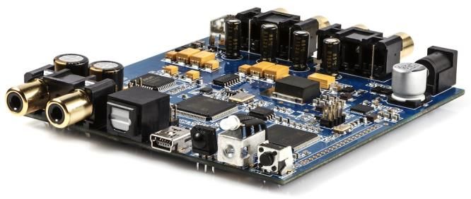
TABLE OF CONTENTS
Important Information ........................................................................................................................................ 5
  System Requirements ...................................................................................................................................... 5
  Disclaimer/Warning ......................................................................................................................................... 5
  Warranty Terms ............................................................................................................................................... 5
  FCC Class B Statement...................................................................................................................................... 6
  CE Mark Statement .......................................................................................................................................... 6
  A note on this manual ...................................................................................................................................... 6
1     Product overview.......................................................................................................................................... 7
    1.1    Typical applications .............................................................................................................................. 7
2     The miniDSP workflow.................................................................................................................................. 9
3     Software installation .................................................................................................................................. 11
    3.1     Windows ............................................................................................................................................ 11
       3.1.1     Possible Windows installation issues........................................................................................... 11
       3.1.2     2x4 HD plugin installation ........................................................................................................... 12
       3.1.3     USB Driver installation ................................................................................................................ 12
    3.2     Mac .................................................................................................................................................... 13
       3.2.1     Possible Mac installation issues .................................................................................................. 13
       3.2.2     2x4 HD plugin installation ........................................................................................................... 13
4     Hardware connectivity................................................................................................................................ 14
    4.1   Digital input........................................................................................................................................ 14
    4.2   Analog inputs and outputs .................................................................................................................. 14
    4.3   USB .................................................................................................................................................... 15
    4.4   DC power ........................................................................................................................................... 15
5     The 2x4 HD Kit board .................................................................................................................................. 16
    5.1     Input sensitivity Jumpers .................................................................................................................... 16
    5.2     I2S headers......................................................................................................................................... 17
       5.2.1     I2S overview ............................................................................................................................... 17
       5.2.2     I2S details ................................................................................................................................... 18
       5.2.3     Additional I2S usage notes .......................................................................................................... 18
6     Configuring the 2x4 HD ............................................................................................................................... 19
    6.1     Synchronizing with the processor ....................................................................................................... 20
    6.2     Signal flow and processing overview................................................................................................... 21
    6.3     Key features ....................................................................................................................................... 21
       6.3.1     Master control ............................................................................................................................ 21
       6.3.2     Configuration/preset selection ................................................................................................... 22
       6.3.3     Inputs & Routing ......................................................................................................................... 22
       6.3.4     Input selection ............................................................................................................................ 22
       6.3.5     Routing matrix ............................................................................................................................ 23
       6.3.6     Outputs ...................................................................................................................................... 23

miniDSP Ltd, Hong Kong / www.minidsp.com / Features and specifications subject to change without prior notice                                                  3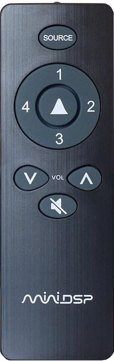
6.4     Plugin configuration guide .................................................................................................................. 24
       6.4.1     Subwoofer control / multisub ..................................................................................................... 24
       6.4.2     Subwoofer integration (2.1 system) ............................................................................................ 25
       6.4.3     Two-way active speaker .............................................................................................................. 26
       6.4.4     Stereo supporting woofers/FAST ................................................................................................ 27
7     Plugin reference.......................................................................................................................................... 28
    7.1     Input channel strips ............................................................................................................................ 28
    7.2     Routing .............................................................................................................................................. 29
    7.3     Output tab ......................................................................................................................................... 30
       7.3.1      Channel strip layout .................................................................................................................... 30
       7.3.2      Channel label .............................................................................................................................. 30
       7.3.3      Level meter and gain control ...................................................................................................... 30
       7.3.4      Parametric EQ............................................................................................................................. 31
       7.3.5      Crossover.................................................................................................................................... 33
       7.3.6      Compressor ................................................................................................................................ 35
       7.3.7      FIR .............................................................................................................................................. 36
       7.3.8      Invert and mute .......................................................................................................................... 36
       7.3.9      Time delay .................................................................................................................................. 36
    7.4     Custom biquad programming ............................................................................................................. 37
       7.4.1      What’s a “biquad? ...................................................................................................................... 37
       7.4.2      Using custom biquad programming ............................................................................................ 37
       7.4.3      Biquad design software............................................................................................................... 39
    7.5     FIR filtering and design ....................................................................................................................... 40
       7.5.1      FIR filtering overview .................................................................................................................. 41
       7.5.2      FIR filter design software ............................................................................................................ 41
       7.5.3      Filter file format.......................................................................................................................... 41
       7.5.4      Loading filter coefficients ............................................................................................................ 42
    7.6     Working with configurations .............................................................................................................. 43
       7.6.1      Online and offline mode ............................................................................................................. 43
       7.6.2      Selecting a configuration ............................................................................................................ 43
       7.6.3      Saving and loading configurations ............................................................................................... 44
       7.6.4      Restoring to defaults................................................................................................................... 44
    7.7     Keyboard shortcuts ............................................................................................................................ 45
8     USB Audio ................................................................................................................................................... 46
    8.1    Mac OS X ............................................................................................................................................ 46
    8.2    Windows ............................................................................................................................................ 47
9     Infrared remote control .............................................................................................................................. 48
10 Additional information ............................................................................................................................... 49
  10.1 Specifications ..................................................................................................................................... 49
  10.2 Firmware upgrade .............................................................................................................................. 50
    10.2.1 Windows .................................................................................................................................... 50
    10.2.2 macOS / OS X .............................................................................................................................. 52
  10.3 Troubleshooting ................................................................................................................................. 54
  10.4 Obtaining support .............................................................................................................................. 55

miniDSP Ltd, Hong Kong / www.minidsp.com / Features and specifications subject to change without prior notice                                                  4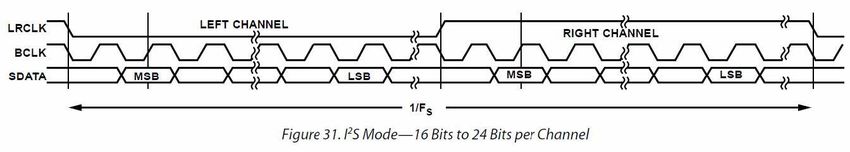
IMPORTANT INFORMATION
Please read the following information before use. In case of any questions, please contact miniDSP via the
support portal at support.minidsp.com.

SYSTEM REQUIREMENTS
To configure the miniDSP audio processor, you will require a Windows PC or Apple Mac OS X computer with
the following minimum specification:
Windows
 • PC with 1GHz or higher processor clock speed. Intel® Pentium®/Celeron® family, or AMD K6®/AMD
   Athlon®/AMD Duron® family, or compatible processor recommended.
 • 512 megabytes (MB) of RAM or higher
 • Keyboard and mouse or compatible pointing device
 • USB 2.0 port
 • Microsoft• ® Windows® Vista® SP1/ XP pro SP2/Win7/Win8.1/Win10
 • Microsoft• ® .NET framework v3.5 or later
Mac OS X
 • Intel-based Mac with 1 GHz or higher processor clock speed
 • 512 megabytes (MB) of RAM or higher
 • Keyboard and mouse or compatible pointing device
 • USB 2.0 port
 • OS X 10.8 or higher, macOS 10.12 or higher

DISCLAIMER/WARNING
miniDSP cannot be held responsible for any damage that may result from the improper use of this product
or incorrect configuration of its settings. As with any other product, we recommend that you carefully read
this manual and other technical notes to ensure that you fully understand how to operate this product. The
miniDSP audio processor is a powerful tool, and misuse or misconfiguration, such as incorrectly set gains or
excessive boost, can produce signals that may damage your audio system.
As a general guideline, you should perform the initial configuration of the miniDSP audio processor before
enabling audio through any connected output device or amplification. Doing so will help ensure that the
software is correctly configured.
Finally, note that the miniDSP audio processor is a very flexible device, and many of the questions we receive
at the tech support department are already answered in this user manual and in the online application notes
on the miniDSP.com website. So please take the time to carefully read this user manual and the online
technical support. Thanks for your understanding!

WARRANTY TERMS
miniDSP Ltd warrants this product to be free from defects in materials and workmanship for a period of one
year from the invoice date. Our warranty does not cover failure of the product due to incorrect connection

miniDSP Ltd, Hong Kong / www.minidsp.com / Features and specifications subject to change without prior notice   5

or installation, improper or undocumented use, unauthorized servicing, modification or alteration of the unit
in any way, or any usage outside of that recommended in this manual. If in doubt, contact miniDSP prior to
use.

FCC CLASS B STATEMENT
This device complies with Part 15 of the FCC Rules. Operation is subject to the following two conditions:
 • This device may not cause harmful interference.
 • This device must accept any interference received, including interference that may cause undesired
   operation.
Warning: This equipment has been tested and found to comply with the limits for a Class B digital device,
pursuant to Part 15 of the FCC Rules. These limits are designed to provide reasonable protection. This
equipment generates, uses and can radiate radio frequency energy and, if not installed and used in
accordance with the instructions, may cause interference to radio communications. However, there is no
guarantee that interference will not occur in a particular installation. If this equipment does cause harmful
interference to radio or television reception, which can be determined by turning the equipment off and on,
the user is encouraged to try to correct the interference by one or more of the following measures:
 • Reorient or relocate the receiving antenna.
 • Increase the separation between the equipment and receiver.
 • Connect the equipment into an outlet on a circuit different from that to which the receiver is connected.
 • Consult the dealer or an experienced radio/TV technician for help.
Notice: Shielded interface cable must be used in order to comply with emission limits.
Notice: Changes or modification not expressly approved by the party responsible for compliance could void
the user’s authority to operate the equipment.

CE MARK STATEMENT
The 2x4 HD has passed the test performed according to European Standard EN 55022 Class B.

A NOTE ON THIS MANUAL
This User Manual is designed for reading in both print and on the computer. If printing the manual, please
print double-sided. The embedded page size is 8 ½” x 11”. Printing on A4 paper will result in a slightly
reduced size.

miniDSP Ltd, Hong Kong / www.minidsp.com / Features and specifications subject to change without prior notice   6
1 PRODUCT OVERVIEW
Thank you for choosing the miniDSP 2x4 HD or 2x4 HD Kit audio processor. The miniDSP 2x4 HD is an
extremely compact yet powerful and flexible digital audio processor for active crossover and other audio
processing applications. It features:
    •    Asynchronous XMOS USB input for streaming audio (up to 192 kHz)
    •    Stereo digital optical TOSLINK input
    •    Two analog input channels and four analog output channels
    •    Parametric EQ on all input and output channels, Butterworth and Linkwitz-Riley crossovers up to 48
         dB/octave, and advanced biquad programming for an unlimited range of filters and crossover types
    •    FIR filtering on every output channel (total 4096 taps)
    •    Routing matrix for flexible channel assignment and configuration
    •    Real-time configuration of all processing parameters
    •    Volume control by infrared remote
    •    Four on-board presets, selectable by infrared remote

1.1 TYPICAL APPLICATIONS
The miniDSP 2x4 HD has a wide range of applications in home and professional audio. In this example, the
2x4 HD acts as both preamp and two-way crossover:

                                      Figure 1 - 2x4 HD as preamp and 2-way crossover

miniDSP Ltd, Hong Kong / www.minidsp.com / Features and specifications subject to change without prior notice   7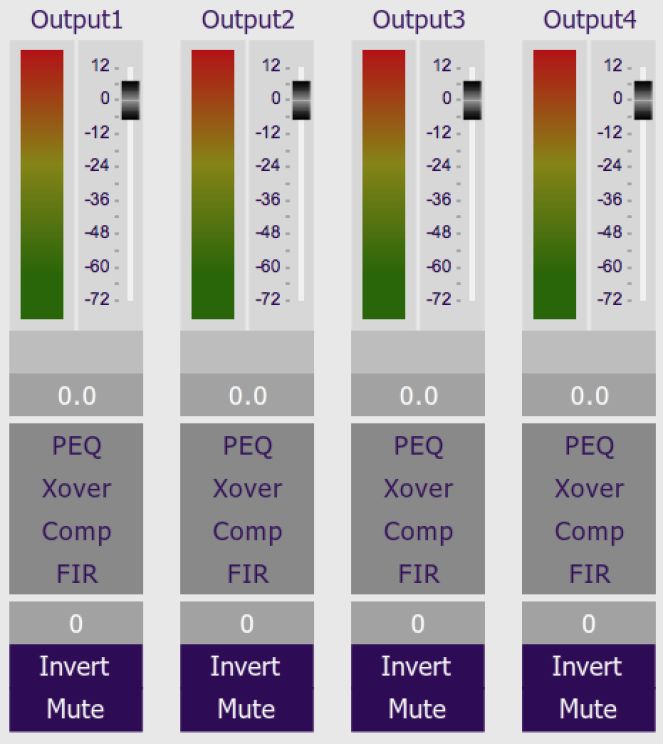
The miniDSP 2x4 HD is a perfect solution for subwoofer integration, providing accurate and flexible
integration between the subwoofers and the main speakers, as well as comprehensive EQ and tuning
options. In this role, the 2x4 HD is added after the preamp, as shown here:

                                Figure 2 - 2x4 HD for subwoofer integration (2.1-way)

The miniDSP 2x4 HD is a perfect solution for multi-subwoofer management for home theater. Driven from
the A/V receiver’s subwoofer output, the 2x4 HD can be used to adjust gain and delays individually for each
subwoofer, and provide parametric EQ both singly and for all subwoofers:

                                     Figure 3 - 2x4 HD for multisub management

The 2x4 HD Kit allows construction of the 2x4 HD circuit board into more sophisticated builds that combine
other components such as power amplifier boards.

miniDSP Ltd, Hong Kong / www.minidsp.com / Features and specifications subject to change without prior notice   8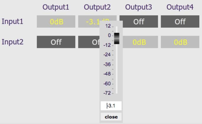
2 THE MINIDSP WORKFLOW
We strongly recommend taking a methodical approach to your new miniDSP audio processor. Remember
that the audio processor is a powerful tool and incorrect settings can potentially cause damage to your
system. Please follow the steps below carefully.
1. Download and install the software
                  When your order ships, your ordered plugin (or plugins) will be available from the User
                  Downloads section of the miniDSP website. Download and install the plugin and USB driver
                  (for Windows), as described in Software installation on page 11.
2. Familiarize yourself with the plugin
                  Before connecting your computer to the processor, start the plugin and familiarize yourself
                  with its user interface. Click on and explore each of the tabs (Input&Routing, Output). For
                  more information, see Configuring the 2x4 HD starting on page 19.
                  At this time, the plugin is still in offline mode, so any changes you make will not be
                  downloaded into the miniDSP hardware. Since all of the processing parameters will be reset
                  in the next step, you can feel free to experiment at this point.
3. Reset all parameters
                  From the Restore menu, select the Factory Default option. This will reset all processing
                  parameters back to the defaults and ensure that you have a "clean slate" for the next step.
4. Perform initial configuration
                  Use the plugin to set up an initial audio processing configuration as intended for your
                  application. For example, typical things that can be done at this point are to:
                  •     Set the labels of input and output channels
                  •     Mute unused input and output channels
                  •     Set crossover frequencies and slopes
                  •     Set up any essential equalization
5. Save configuration
                  Save your initial configuration to a file. A configuration is the set of all audio processing
                  parameters. You should save your configuration to a file on a regular basis, to ensure that
                  you do not lose your work if you inadvertently restore the processor to default settings. For
                  more information on configurations, see Working with configurations on page 43.
6. Make audio connections
                  With the initial configuration done and now that you are familiar with the various controls,
                  it’s time to connect the miniDSP 2x4 HD into your system. Ensure that all power is turned off
                  when making audio connections. See Hardware connectivity on page 14.
7. Go into online mode
                  Apply power to the processor. (See DC power on page 15 for more information. Leave other
                  equipment turned off at this stage.) Connect the USB cable to your computer, click on the
                  Connect&Synchronize button, and select the Synchronize option. If all goes well, you are

miniDSP Ltd, Hong Kong / www.minidsp.com / Features and specifications subject to change without prior notice     9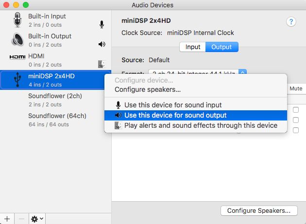
now in online mode, and any changes that you now make in the plugin user interface will be
                  immediately sent to the processor.
                  Before proceeding, click on each Configuration preset button (Config 1, 2, etc.) to ensure
                  that all presets have been synchronized and/or set to defaults.
                  For more information, see Synchronizing with the processor on page 20.
8. Initial audio check
                  Power on your connected equipment, first on the input side (e.g. source or preamp), then on
                  the output side (e.g. power amps). Set a low volume (turn the volume on your source down
                  low, or program the infrared remote and reduce the master volume to -50 dB) and start
                  playing music or a pink noise test signal. Gradually increase the volume until your hear audio
                  quietly coming from the speakers. Verify that the plugin is performing the intended function.
                  (For example, if implementing a two-way crossover, confirm that the tweeter is playing high
                  frequencies, and that the woofer is playing low frequencies.)
9. Fine-tune your configuration
                  With your initial setup running, you can now proceed to fine-tune and optimize your system.
                  You will need to perform acoustic measurements and use the configuration screens to adjust
                  processing parameters.
                  Be sure to save your configuration on a regular basis while working on fine-tuning it.
                  Configurations can be saved to different files, in order to archive different versions, or to
                  enable auditioning of alternative configurations.
10. Continue to operate offline
                  With your miniDSP processor configured, you can continue to operate in offline mode—that
                  is, without the plugin software running. The processor “remembers” the configuration last
                  set, and will continue to operate without the computer.
                  Note: while in offline mode, the configuration can still be modified in the plugin interface.
                  These changes will not be downloaded to the processor until it is synchronized again. See
                  Working with configurations on page 43.

miniDSP Ltd, Hong Kong / www.minidsp.com / Features and specifications subject to change without prior notice     10
3 SOFTWARE INSTALLATION If you purchased your product directly from miniDSP, your software will be available from the User Downloads section of the miniDSP website when your order ships. You will need to be logged into the website with the account you created when purchasing to access the download. If you purchased your product from a miniDSP dealer, you will receive a coupon together with the product. Redeem this coupon and select the Plugin Group “MiniDSP 2x4 HD1” at the link below: • https://www.minidsp.com/support/redeem-coupon The User Downloads link is visible from the dropdown menu at the top right of the website page: Navigate to the miniDSP Plug-ins section and download the zip file under the heading miniDSP 2x4 HD1. Unzip the downloaded file (on Windows, right-click and select “Extract All...”; on Mac, double-click). Note: the plugin may need a network connection the first time the plugin is used. If the plugin does not start properly, see Troubleshooting. 3.1 WINDOWS 3.1.1 Possible Windows installation issues The miniDSP software requires that a number of other frameworks be installed for it to work. For Windows 7 and later, these packages should be installed automatically. For earlier versions of Windows, please download and install the following frameworks before attempting to install any miniDSP software. You can also manually install these if you receive an error message that required software is missing. • Microsoft .NET framework (version 3.5 or later) • Microsoft Visual C++ 2010 Redistributable Package: for x86 (32-bit operating system) or x64 (64-bit operating system). miniDSP Ltd, Hong Kong / www.minidsp.com / Features and specifications subject to change without prior notice 11
3.1.2 2x4 HD plugin installation
1.    Navigate to the Plugins folder of the software download and then to the Windows folder.
2.    Double-click on the MiniDSP_2x4_HD.exe installer program to run it. We recommend that you accept
      the default installation settings.
3.    The plugin will start automatically if you accepted the default installation settings. To make it quicker to
      run in future, right-click on its icon in the taskbar and select “Pin to taskbar.”

3.1.3 USB Driver installation
1.    Connect the 2x4 HD to the computer using the supplied USB cable, and power it on.
2.    Navigate to the WinDrivers folder of the software download and double-click on the appropriate
      installer:
     • miniDSP_UAC2_v2.29.3_ForWinXP_Vista.exe for Windows XP and Vista
     • miniDSP_UAC2_v4.47.0_ForWin7_8_10.exe for Windows 7, 8, and 10
(The version number embedded in the filename may be different.)
We recommend accepting the default installation location. Once the driver installation completes, click the
Finish button.

             The Windows PC will not be able to communicate properly with the 2x4 HD if you did not have
             the it connected by USB and powered on when you installed the driver. If that is the case, you will
             need to uninstall the driver, connect the 2x4 HD, power it on, and run the installer again.

Note: the first time you run the plugin, you may see a warning from Windows Firewall that looks similar to
the screenshot below. (The text “[app]” will be replaced by the application name.) Ensure that “Private
networks...” is checked and “Public networks...” is not checked. Then click on “Allow access.”

miniDSP Ltd, Hong Kong / www.minidsp.com / Features and specifications subject to change without prior notice   12
3.2 MAC
3.2.1 Possible Mac installation issues
If double-clicking on an installer brings up a message that the installer cannot run, use this alternate method
(note that the name of the installer will be MiniDSP-2x4-HD.pkg, not MiniDSP_Plugin.pkg as shown in the
screenshots):
1. Right-click on the installer (or click while holding the Control key).
2. On the menu that pops up, move the mouse over the “Open With” item and then click on “Installer
(default).”
3. The following window will appear. Click on “Open.”
3.2.2 2x4 HD plugin installation
1. Navigate to the Plugins folder of the software download and then to the Mac folder.
2. The installer program is named MiniDSP-2x4-HD.pkg. To run it, double-click on it, or right-click and
open as described above. We recommend that you accept the default installation settings.
3. To run the MiniDSP-2x4-HD plugin, locate it in the Applications -> miniDSP folder and double-click on it.
To make it easier to run in future, right-click on its dock icon and select Options -> Keep in Dock.
Note: No USB driver installation is required for Mac OS X.
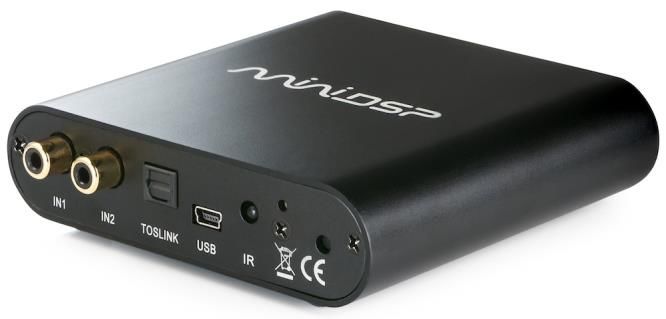
miniDSP Ltd, Hong Kong / www.minidsp.com / Features and specifications subject to change without prior notice 134 HARDWARE CONNECTIVITY 4.1 DIGITAL INPUT Connect a single digital source to the optical (TOSLINK) connector. Thanks to its asynchronous sample rate convertor (ASRC), all sample rates between 44.1 and 192 kHz are accepted. Note: the digital input accepts only a stereo PCM digital signal. It does not accept encoded or multichannel digital audio (such as Dolby Digital or DTS). 4.2 ANALOG INPUTS AND OUTPUTS Connect an analog source or preamplifier to the RCA connectors on the front panel, and connect the four analog outputs to power amplification or subwoofer(s). Be sure to take careful note of the channel numbering shown in this diagram and on the rear panel. miniDSP Ltd, Hong Kong / www.minidsp.com / Features and specifications subject to change without prior notice 14
4.3 USB
Connect the USB (Type B mini) port of the miniDSP 2x4 HD to a free USB 2.0 port on your computer using the
supplied cable. The USB is used for:
 • Configuration and real-time control of the miniDSP 2x4 HD,
 • Streaming audio from a computer or other device such as a music streamer, at up to 192 kHz, and
 • Streaming the processed audio (four output channels) from the miniDSP 2x4 HD to the computer.

4.4 DC POWER
The supplied 12 VDC power supply includes a set of interchangeable power pins (for USA, UK, Europe and
Australia). Fit the correct pins for your country. Connect the DC plug to the 12 VDC power socket.

           Apply power to the processor only after all input and output connections have been made. The
           processor can usually be left powered on. If powered on and off, the following sequence is
           recommended:
           • On: Power on line-level equipment, including the 2x4 HD, then turn on power amplification.
           • Off: Turn power amplification off, then power off line-level equipment, including the 2x4 HD.

miniDSP Ltd, Hong Kong / www.minidsp.com / Features and specifications subject to change without prior notice   15
5 THE 2X4 HD KIT BOARD
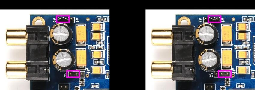
5.1 INPUT SENSITIVITY JUMPERS
The 2x4 HD Kit board is exactly the same as the 2x4 HD “in a box”, but without the box. All functionality and
I/O is identical. The board can be built into your own box and/or combined with other boards such as power
amplifiers. This annotated photograph shows the main features of the board:
The only user-accessible jumpers are used to set the analog input sensitivity. The jumpers are located near
the RCA input jacks, and can be used to set the analog input sensitivity to either 2 VRMS or 4 VRMS, as
shown by the highlighted locations below. The default setting as shipped is 2 VRMS.
The board must be powered OFF when changing these jumpers.
miniDSP Ltd, Hong Kong / www.minidsp.com / Features and specifications subject to change without prior notice 165.2 I2S HEADERS
Headers J7 is provided for connection of output circuitry via I2S. The pinouts are shown below.
J7 Below the Toslink
3.3 1 2 GND
NC 3 4 NC
NC 5 6 NC
NC 7 8 NC
I2S CH 1/2 9 10 I2S CH 3/4
LRCLK 11 12 BCLK
MCLK 13 14 GND
5.2.1 I2S overview
I2S, or Inter IC Sound, is an electrical serial bus used to interface digital audio devices at the chip and circuit
board level. An I2S interface consists of up to three clocks, and a data line for each pair of channels. There
are three types of clock:
MCLK The master clock that the 2x4HD uses internally. This clock is always provided as an output
by the 2x4HD, and connected circuitry can choose whether or not to use it.
LRCLK The frame synchronization clock, also known as the word clock. This clock is equal to the
sampling frequency (Fs) of the audio signal.
BCLK The bit clock (also known as shift clock or system clock). This is always equal to 64 x Fs.
miniDSP Ltd, Hong Kong / www.minidsp.com / Features and specifications subject to change without prior notice 17Table 1 summarizes the relation between the clocks for the 96 kHz plugin.
Table 1. I2S clock ratios
Plugin sample rate (LRCLK) Master clock (MCLK) Bit clock (BCLK) MCLK/LRCLK BCLK/LRCLK
96 kHz 24.576 MHz 6.144 MHz 256 64
The timing of data lines is determined by the bit clock and the word clock, as illustrated in the following
diagram:
The 2x4HD board has two I2S output data lines, each carrying two channels of audio. Only output I2S is
enabled in the plugin.
5.2.2 I2S details
The 2x4HD acts in master mode with respect to I2S clocking.
That is, the 2x4HD provides the I2S clocks and the connected devices are expected to receive data using
those clocks. The clocks will match the sample rate of the plugin loaded onto the 2x4HD. See the miniSHARC
User Manual for more information about I2S master and slave modes. Note that:
1. The connected devices may or may not use MCLK. This is dependent on the specifics of the devices.
2. The digital optical and asynchronous USB audio inputs use an onboard asynchronous sample rate
convertor to convert the incoming sample rate to the 2x4HD’s clock domain.
5.2.3 Additional I2S usage notes
I2S is not a “plug and play” protocol. It requires attention to technical details such as clocking and wire
layout. It is a solution for OEMs and advanced DIYers (or professionals) with suitable knowledge, skills and
measurement equipment. miniDSP cannot be held responsible for any damage you do to the board (outside
normal warranty) or to your external equipment.
Be sure to take the following precautions when designing your I2S interface and wiring:
General I2S usage notes
• Unbuffered I2S lines must be kept short to ensure clock and data integrity.
• If driving longer lines, buffers may be required for the clock signals (MCLK, LRCLK, and BLCK).
• Observe correct grounding and shielding, and keep analog and digital grounds separated.
• Ensure that the clock ratios (as listed in Table 1) are compatible with connected circuits.
• All lines use a 3.3V logic level. Ensure that connected circuits use a compatible level (1.8V, for
example, will not work).
miniDSP Ltd, Hong Kong / www.minidsp.com / Features and specifications subject to change without prior notice 186 CONFIGURING THE 2X4 HD
The 2x4 HD processor is configured with the miniDSP-2x4-HD plugin / user interface program. Once fully
configured, the computer is no longer required, as source and preset selection can be done with a remote
control. If desired, however, the plugin can remain connected during use for real-time (“live”) control of all
audio processing.
This screenshot shows the miniDSP-2x4-HD plugin with the key areas highlighted:
During initial configuration of the processor, it is strongly recommended that any connected
amplification be powered off.
miniDSP Ltd, Hong Kong / www.minidsp.com / Features and specifications subject to change without prior notice 196.1 SYNCHRONIZING WITH THE PROCESSOR
Communication with the processor takes place over a USB connection. Ensure that the computer is
connected to the miniDSP 2x4 HD by a USB 2.0 port. Then click on the Connect button:
The first time you connect, or if you have made any changes to any data in the user interface, the following
dialog box will appear:
The options are:
Synchronize Config
Download the currently selected configuration into the corresponding configuration preset
of the processor. After downloading the configuration data, the plugin is in online mode and
any changes to processing parameters will be downloaded immediately in real time. That is,
the user interface is now “live.”
Synchronize and Upgrade
This is similar to Synchronize Config, but also upgrades the internal data of the processor.
This option may appear after downloading and installing an updated version of the plugin.
Restore Config
Restore the data in the currently selected configuration to the factory defaults. When using
this option, any connected equipment should be muted or powered off until you have set
the configuration to a working state. Note that the configuration data will be lost, so if
needed, ensure that you have saved the configuration to a file prior to using this option.
Help This option brings up a help screen explaining the options.
Cancel This option cancels the attempt to connect to the processor. The plugin will remain in offline
mode.
miniDSP Ltd, Hong Kong / www.minidsp.com / Features and specifications subject to change without prior notice 206.2 SIGNAL FLOW AND PROCESSING OVERVIEW The signal flow diagram of the 2x4 HD is shown in the diagram below. One of the three stereo input sources is selected by the user and passed to the input channel processing blocks. The stereo analog input is converted to digital form. These blocks include input gain, level metering, and parametric EQ. The processed input channels are fed into a 2-in 4-out routing matrix. The routing matrix enables the 2x4 HD to be used in a number of different applications. Section 6.4 provides a configuration guide for several common applications. The outputs from the routing matrix are processed through a comprehensive set of DSP functions – crossover filters (high pass and low pass), parametric EQ, FIR filtering, and individual gain and delay adjustments. You can configure these as needed according to your particular application. Finally, the four output channels are converted to analog so they can be fed to your power amps and/or subwoofers. 6.3 KEY FEATURES This section summarizes the key features of the plugin. 6.3.1 Master control Once the plugin is online, the items in the Master Control area are active. The Mute button disables all audio output: The Master Volume display shows the current volume setting. The master volume can be set directly by clicking here and typing a new value. It can also be set with the remote control: The IP Address and Auto fields are for use with networked control of the plugin using the miniDSP WI-DG Wifi/Ethernet to USB bridge. See the Wi-DG User Manual for details. miniDSP Ltd, Hong Kong / www.minidsp.com / Features and specifications subject to change without prior notice 21
6.3.2 Configuration/preset selection
The set of data that controls the back-end processing is called a configuration. This includes crossovers,
parametric EQ and the routing matrix. It does not include the master volume or mute status.
Four configurations are stored onboard. The currently selected preset is indicated by a dark background:

To switch to a different preset, just click on the desired button:

6.3.3 Inputs & Routing
The Inputs & Routing tab displays two input channel control strips and the routing matrix.

6.3.4 Input selection
When the plugin is connected to the 2x4 HD, the currently selected input appears next to the “Inputs” label.
Click on the current input name to drop down a selector menu, from which you can select a different input.
(You can also select the input with a remote control – see page 46.)

miniDSP Ltd, Hong Kong / www.minidsp.com / Features and specifications subject to change without prior notice   22
6.3.5 Routing matrix
The routing matrix on the Inputs & Routing tab directs input channels (along the left) to output channels
(along the top). To turn on routing for a cross-point, click on that cross-point. Both inputs can be mixed to
each output if desired, and the mix level can be set individually for each input.

6.3.6 Outputs
The Outputs tab displays a row of four output channel control strips. All output channels are identical.

Each channel has an individual gain adjustment slider, and a graphical and numerical display of the current
signal level on that channel. A comprehensive set of signal processing functions is accessed with the buttons
PEQ (parametric EQ), Xover (crossover), Comp (compressor/limiter) and FIR (FIR filter).

miniDSP Ltd, Hong Kong / www.minidsp.com / Features and specifications subject to change without prior notice   23
6.4 PLUGIN CONFIGURATION GUIDE
This section provides a quick overview of a range of common configurations using the 2x4 HD.

6.4.1 Subwoofer control / multisub
The miniDSP 2x4 HD can be used to provide independent control of up to four subwoofers. Each subwoofer
can have individual time delay, gain, and EQ applied as needed. Here is a typical connection diagram for a
home theater system with three subwoofers:

Following is a brief summary of the key configuration settings needed. On the Outputs tab:
    •    Rename the output channels to match the number of subs you have i.e. “Sub 1,” “Sub 2,” etc.
    •    Mute any unused output channels.
    •    Check that the crossover filters of all output channels are bypassed:

         (Normally, upstream equipment like the A/V receiver or processor implements lowpass crossover
         filters as part of its bass management processing. In some cases, such as when using a 2x4 HD to add
         multisub capability to a stereo system, you may need to use lowpass filters in the 2x4 HD.)
On the Inputs & Routing tab, set the routing matrix like this (for the three-sub HT example shown above):

After you have set up the plugin, be sure to save your configuration to a file. For detailed information on
tuning multiple subwoofers, see this application note on our website:
    •    Tuning multiple subwoofers with miniDSP

miniDSP Ltd, Hong Kong / www.minidsp.com / Features and specifications subject to change without prior notice   24
6.4.2 Subwoofer integration (2.1 system)
The miniDSP 2x4 HD is ideal for integrating a subwoofer into a stereo system. This diagram illustrates the
typical connections:
Following is a brief summary of the key configuration settings needed. On the Outputs tab:
• Rename the output channels (from left to right) to “Left Sp”, “Right Sp”, “Sub” and “Unused”.
• Mute channel 4 (“Unused”).
• Set a high pass crossover filter on channels 1 and 2 (“Left Sp” and “Right Sp”). For example:
• Set a low pass crossover filter on channel 3 (“Sub”). For example:
On the Inputs and Routing tab, set the routing matrix like this:
We recommend that you do acoustic measurements to check and fine-tune your subwoofer crossover
settings. For more detail, refer to the app note linked above. After you have set up the plugin, be sure to
save your configuration to a file. For more information, see this application note on our website:
• Subwoofer integration with the miniDSP 2x4 HD
miniDSP Ltd, Hong Kong / www.minidsp.com / Features and specifications subject to change without prior notice 256.4.3 Two-way active speaker
The 2x4 HD is a perfect solution for implementing a two-way active speaker. This diagram illustrates the
connections:
Following is a brief summary of the key configuration settings needed. On the Outputs tab, rename the
output channels to “Left W”, “Left Tw”, “Right W” and “Right Tw”.
On the Inputs & Routing tab, set the routing matrix like this:
On the Outputs tab again:
• Use Room EQ Wizard or a similar program to measure each individual woofer and tweeter and to
equalize their response flat with the PEQ blocks. (See the app note linked above for details.)
• Set up your high pass and low pass crossover filters. This is a typical low pass setting for the woofers:
This is a typical high pass setting for the tweeters:
After you have set up the plugin, be sure to save your configuration to a file. For more detailed information
on implementing a two-way speaker, see this application note on our website:
• Designing a 2-way active speaker with the miniDSP 2x4 HD
miniDSP Ltd, Hong Kong / www.minidsp.com / Features and specifications subject to change without prior notice 266.4.4 Stereo supporting woofers/FAST
In a configuration with two full range speakers supplemented by supporting woofers (sometimes known as
“FAST”), the plugin is set up to split the frequency range to the woofer and full range speakers. This diagram
illustrates the connections:
Following is a brief summary of the key configuration settings needed. On the Outputs tab:
• Rename the output channels (from left to right) to “Left FR”, “Right FR”, “Left W” and “Right W”.
• Set a high pass crossover filter on channels 1 and 2 (“Left FR” and “Right FR”). For example:
• Set a low pass crossover filter on channels 3 and 4 (“Left W” and “Right W”). For example:
On the Inputs & Routing tab, set the routing matrix like this:
We recommend that you take acoustic measurements to check and fine-tune your crossover settings. After
you have set up the plugin, be sure to save your configuration to a file.
miniDSP Ltd, Hong Kong / www.minidsp.com / Features and specifications subject to change without prior notice 277 PLUGIN REFERENCE
This section provides full details on each of the plugin processing blocks.
7.1 INPUT CHANNEL STRIPS
Channel label
Each input channel has a customizable label, which is shown at the top of the channel strip.
This label also appears on the routing matrix. To change the label, click on it, type a new
label (up to eight characters), and press the Return key.
Level meter, Current RMS level
Displays the current signal level in real time. (The plugin must be in online mode to display
signal levels.)
Gain adjustment
The gain of each channel can be adjusted by moving the Gain Adjustment slider, or by typing
the desired gain into the Current Gain text box. The maximum gain setting is 12 dB, and the
minimum gain setting is –72 dB. (0 dB, the default, is unity gain or no change in level.)
PEQ settings
Click on this button to open the parametric EQ settings window for that channel. There are
ten parametric EQ filters on each input channel. For more details, see Parametric EQ on page
31.
Mute
Press this button to mute that input channel. The button color and label changes to show
that the channel is muted.
miniDSP Ltd, Hong Kong / www.minidsp.com / Features and specifications subject to change without prior notice 287.2 ROUTING The routing matrix is used to direct input channels (along the left) to output channels (along the top). To turn on routing for a cross-point, click on that cross-point. The display will change from “Off” to show the mix level (0 dB by default). Below is the default routing matrix. The input and output channel names displayed on the matrix match those set on the input and output control strips: Changing the channel labels on the control strips changes them on the routing matrix, as an aid to ensuring correct configuration. For example: At each cross-point, the gain of the signal being mixed can be adjusted to a value between -72 and +12 dB. To adjust the gain, right-click on the cross-point and a gain control will appear. Adjust the gain with the slider, or by typing in the value directly, then click close: miniDSP Ltd, Hong Kong / www.minidsp.com / Features and specifications subject to change without prior notice 29
7.3 OUTPUT TAB
The Output tab displays a row of four output channel control strips. All output channels are identical.

7.3.1 Channel strip layout
Each output channel has a complete "strip" of controls.

7.3.2 Channel label
Each output channel has a customizable label, which is shown at the top of the channel strip. This label also
appears on the routing matrix. To change the label, click on it, type a new label (up to eight characters), and
press the Return key.

7.3.3 Level meter and gain control
Level meter, current RMS level
                  Displays the current signal level in real time. (The plugin must be in online mode to display
                  signal levels.)
Gain adjustment
                  The gain of each channel can be adjusted by moving the Gain Adjustment slider, or by typing
                  the desired gain into the Current Gain text box. The maximum gain setting is 12 dB, and the
                  minimum gain setting is –72 dB. (0 dB, the default, is unity gain or no change in level.)

miniDSP Ltd, Hong Kong / www.minidsp.com / Features and specifications subject to change without prior notice     30
7.3.4 Parametric EQ Parametric equalization (PEQ) is a flexible type of equalization filter. It can be used to correct for errors in loudspeaker output, to compensate for acoustic room effects, and to tailor the overall system response for best sound. Click on the PEQ button to open the parametric equalizer settings window: There are ten parametric EQ filters on each input and output channel. The window displays a frequency response graph showing the combined response of all enabled parametric filters on that channel. For example, the screenshot above shows a response curve created with a low-shelf boost filter at 100 Hz, a dip at 500 Hz, and a high-shelf cut filter at 5000 Hz. Hovering the mouse over the curve brings up an overlay showing the frequency and the gain at that frequency. Each channel can be linked to one other channel. When a channel is linked to another, the PEQ settings of that channel are mirrored to the other. Typically, the corresponding drivers on the left and right channels are linked: left and right tweeter, left and right woofer, and so on. To link a channel, select the other channel from the drop-down menu at the top left of the PEQ screen, and click the Link checkbox. miniDSP Ltd, Hong Kong / www.minidsp.com / Features and specifications subject to change without prior notice 31
EQ band selection
                  Click on the tabs EQ1, EQ2, etc. to display the parameters for that filter.
Basic/Advanced
                  By default, each filter is in basic mode, and shows the controls described below. Advanced
                  mode enables custom biquad programming for almost infinite flexibility in filter
                  implementation. This is described in Custom biquad programming on page 37.
Filter type
                  Selects the type of filter:
                  PEAK               Create a dip or a peak in the frequency response.
                  LOW_SHELF          Reduce or increase part of the frequency spectrum below a given frequency.
                  HIGH_SHELF         Reduce or increase part of the frequency spectrum above a given frequency.
                  ALL_PASS           Create a phase shift across the frequency band. This can be useful for
                                     correcting phase issues and for simulating analog crossovers.
Frequency
                  For the PEAK filter type, this is the center frequency of the peak or dip. For the HIGH_SHELF
                  and LOW_SHELF filter types, this is the frequency at which the gain is half of the set value.
                  For the ALL_PASS filter type, this is the center frequency of the phase shift.
Gain
                  For the PEAK filter type, this is the gain in dB at the center frequency. For the HIGH_SHELF
                  and LOW_SHELF filter types, this is the gain in dB reached at high or low frequencies
                  respectively. A filter has no effect if its gain is set to 0 dB. Gain can be adjusted in increments
                  of 0.1 dB up to +/- 16 dB. This item is not present for the ALL_PASS filter type.
Q
                  Q controls the “sharpness” of the filter. For the PEAK filter type, lower Q gives a broader
                  peak or dip, while higher Q gives a narrower peak or dip. For the HIGH_SHELF and
                  LOW_SHELF filter types, Q controls how quickly the filter transitions from no gain to
                  maximum gain. For the ALL_PASS filter type, higher Q gives a steeper phase transition.
Bypass
                  The Bypass button enables or disables a filter. The filter is enabled if the button says
                  “BYPASS” and disabled if the button says “BYPASSED” (see screenshot below). Note that this
                  button only enables and bypasses a single filter; all other filters must be bypassed or enabled
                  individually.

miniDSP Ltd, Hong Kong / www.minidsp.com / Features and specifications subject to change without prior notice      32
7.3.5 Crossover Each output channel has independent high pass and low pass filters. Click on the Xover button to open the crossover settings window: Crossovers “split” the frequency band to send to different drivers. In a two-way loudspeaker, a low pass filter is used to remove high frequencies from the signal sent to the woofer, and a high pass filter is used to remove low frequencies from the signal sent to the tweeter. In a three-way speaker, the midrange driver will use both the high pass and low pass filters. Crossover filters can also be used to limit low frequency content delivered to a speaker or subwoofer, to help protect it from over-excursion. Unlike conventional analog crossovers, the flexibility of DSP allows a completely arbitrary mix of different filter slopes and types. Filters can be set at any frequency, or disabled completely. This allows maximum flexibility in matching your crossover to the acoustic characteristics of the loudspeaker drivers. The current channel is displayed in orange, with the others displayed in grey. Hovering the mouse over the curve brings up an overlay showing the frequency and the attenuation at that frequency. miniDSP Ltd, Hong Kong / www.minidsp.com / Features and specifications subject to change without prior notice 33
Basic/Advanced
                  By default, the crossover is in basic mode, and shows the controls described below.
                  Advanced mode enables custom biquad programming for almost infinite flexibility in
                  crossover filter implementation. This is described in Custom biquad programming on page
                  37.
Cutoff Frequency
                  Sets the nominal cutoff frequency of the crossover. In actual fact, the crossover has a more
                  or less gradual transition from “full on” to “full off,” as determined by the filter slope.
Filter type
                  Selects the type and slope of the filter. The steeper the slope, the more quickly frequencies
                  above or below the cutoff frequency are attenuated. There are three types of filter:
                  Butterworth (BW)
                                     Available in 6, 12, 18, 24, 30, 36, 42, and 48 dB/octave, Butterworth
                                     crossover filters are 3 dB down at the cutoff frequency.
                  Linkwitz-Riley (LR)
                                     Available in 12, 24, 36, and 48 dB/octave, Linkwitz-Riley crossover filters are
                                     6 dB down at the cutoff frequency.
                  Bessel
                                     Available in 12 dB/octave only, a Bessel filter gives a more gradual roll-off
                                     through the crossover region.
Bypass
                  Clicking on the Bypass button disables or enables that high
                  pass or low pass filter. The filter is bypassed when the
                  button is "lit".

Each channel can be linked to one other channel. When a channel is linked to another, the crossover settings
of that channel are mirrored to the other. Typically, the corresponding drivers on the left and right channels
are linked: left and right tweeter, left and right woofer, and so on. To link a channel, select the other channel
from the drop-down menu at the top left of the Xover screen, and click the Link checkbox.

miniDSP Ltd, Hong Kong / www.minidsp.com / Features and specifications subject to change without prior notice        34
You can also read