RESEARCH PRODUCTS Front End Interface and Instrument Interface - Owner's Guide - ADInstruments
←
→
Page content transcription
If your browser does not render page correctly, please read the page content below
RESEARCH PRODUCTS

Front End Interface and Instrument Interface
                               Owner’s Guide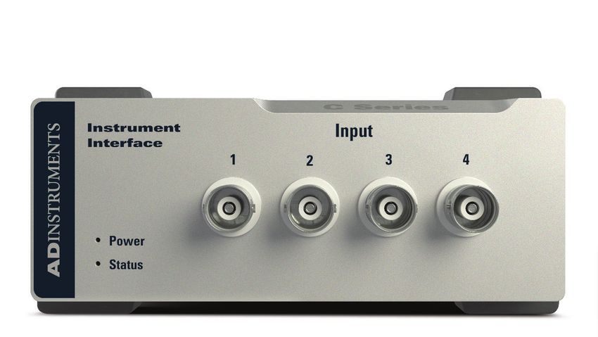
This document is, as far as possible, accurate at the time of release. However, changes may have been
made to the software and hardware it describes since then. ADInstruments NZ Limited reserves the right
to alter specifications as required. Late-breaking information may be supplied separately.

Trademarks of ADInstruments
PowerLab®, LabChart® and ADInstruments® are registered trademarks of ADInstruments NZ Limited.

Other Trademarks
Apple, Mac and Macintosh are registered trademarks of Apple Computer, Inc.
Windows, Windows 7, Windows 8, Windows 10 and Windows Vista are either registered trademarks or
trademarks of Microsoft Corporation.
All other trademarks are the property of their respective owners.

Document Number: U-CSR/OG-01D. Date of issue: 08/21

Copyright © ADInstruments NZ Limited, 2021. All rights reserved. PowerLab, LabChart and ADInstruments
are registered trademarks of ADInstruments NZ Limited. Windows 8, Windows 7, Windows 10, Windows
Vista and .NET Framework are trademarks of Microsoft Corporation. Apple, the Apple logo, MacOS, and
Macintosh are trademarks of Apple Computer Inc. registered in the U.S. and other countries. All other
trademarks are the property of their respective owners.

Web: www.adinstruments.com

Manufactured in Australia for:
ADInstruments NZ Limited,
77 Vogel Street
Dunedin 9016, New Zealand

Technical Support: support.au@adinstruments.com

ii                                                                                     Owner’s Guide
Contents
      1 Safety Notes                                                                                                                             1
        Statement of Intended Use . . . . . . . . . . . . . . . . . . . . . . . . . . . . . . . . . . . . . . . . . . . . . . . . .1
        Safety and Quality Standards . . . . . . . . . . . . . . . . . . . . . . . . . . . . . . . . . . . . . . . . . . . . . . .1
        General Safety Instructions . . . . . . . . . . . . . . . . . . . . . . . . . . . . . . . . . . . . . . . . . . . . . . . . .3
           Cleaning and Sterilization . . . . . . . . . . . . . . . . . . . . . . . . . . . . . . . . . . . . . . . . . . . . . . . .4
        Inspection and Maintenance . . . . . . . . . . . . . . . . . . . . . . . . . . . . . . . . . . . . . . . . . . . . . . . .4
        Environment . . . . . . . . . . . . . . . . . . . . . . . . . . . . . . . . . . . . . . . . . . . . . . . . . . . . . . . . . . . . . .5
           Transport and Storage Conditions . . . . . . . . . . . . . . . . . . . . . . . . . . . . . . . . . . . . . . . .5
           Operating Conditions . . . . . . . . . . . . . . . . . . . . . . . . . . . . . . . . . . . . . . . . . . . . . . . . . . . .5
           Disposal . . . . . . . . . . . . . . . . . . . . . . . . . . . . . . . . . . . . . . . . . . . . . . . . . . . . . . . . . . . . . . . .5

      2 Overview                                                                                                                                 6
        How to Use This Guide. . . . . . . . . . . . . . . . . . . . . . . . . . . . . . . . . . . . . . . . . . . . . . . . . . . . . .7
        Software Installation . . . . . . . . . . . . . . . . . . . . . . . . . . . . . . . . . . . . . . . . . . . . . . . . . . . . . . .7
        PowerLab Check . . . . . . . . . . . . . . . . . . . . . . . . . . . . . . . . . . . . . . . . . . . . . . . . . . . . . . . . . . .7
        Power-on Self Diagnostics . . . . . . . . . . . . . . . . . . . . . . . . . . . . . . . . . . . . . . . . . . . . . . . . . .8

      3 Setting Up                                                                                                                               9
        Connecting the Hardware. . . . . . . . . . . . . . . . . . . . . . . . . . . . . . . . . . . . . . . . . . . . . . . . . .10
           With a PowerLab C . . . . . . . . . . . . . . . . . . . . . . . . . . . . . . . . . . . . . . . . . . . . . . . . . . . . .10
           Without a PowerLab C . . . . . . . . . . . . . . . . . . . . . . . . . . . . . . . . . . . . . . . . . . . . . . . . . 11
        Installing the Software . . . . . . . . . . . . . . . . . . . . . . . . . . . . . . . . . . . . . . . . . . . . . . . . . . . 11
           LabChart 8 . . . . . . . . . . . . . . . . . . . . . . . . . . . . . . . . . . . . . . . . . . . . . . . . . . . . . . . . . . . 11
           LabChart Lightning . . . . . . . . . . . . . . . . . . . . . . . . . . . . . . . . . . . . . . . . . . . . . . . . . . . . 11
           PowerLab Event Link (PEL) . . . . . . . . . . . . . . . . . . . . . . . . . . . . . . . . . . . . . . . . . . . . . 11

      4 PowerLab C                                                                                                                            12
        The PowerLab C . . . . . . . . . . . . . . . . . . . . . . . . . . . . . . . . . . . . . . . . . . . . . . . . . . . . . . . . . 13
          The Front Panel . . . . . . . . . . . . . . . . . . . . . . . . . . . . . . . . . . . . . . . . . . . . . . . . . . . . . . . 13
          The Rear Panel . . . . . . . . . . . . . . . . . . . . . . . . . . . . . . . . . . . . . . . . . . . . . . . . . . . . . . . . .14
             Upstream facing USB Ports . . . . . . . . . . . . . . . . . . . . . . . . . . . . . . . . . . . . . . . . . . .14
             Downstream facing USB Ports . . . . . . . . . . . . . . . . . . . . . . . . . . . . . . . . . . . . . . . .14
             Checking and replacing fuses . . . . . . . . . . . . . . . . . . . . . . . . . . . . . . . . . . . . . . . . 15

iii                                                                                                                        Owner’s Guide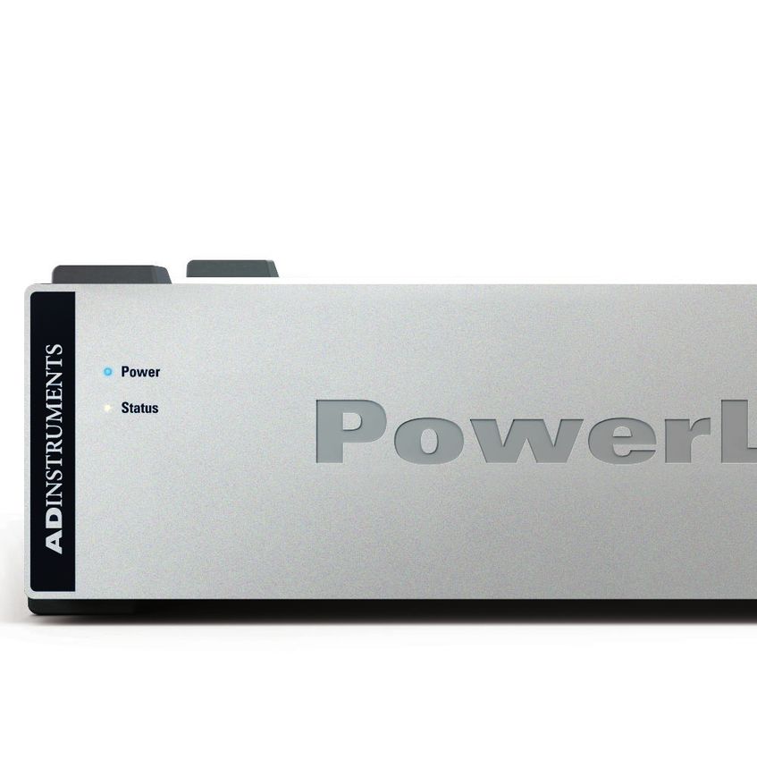
Using Multiple PowerLabs . . . . . . . . . . . . . . . . . . . . . . . . . . . . . . . . . . . . . . . . . . . . . . .16
           Supplied Accessories . . . . . . . . . . . . . . . . . . . . . . . . . . . . . . . . . . . . . . . . . . . . . . . . . . .17

     5 Front End Interface                                                                                                               18
       The Front End Interface. . . . . . . . . . . . . . . . . . . . . . . . . . . . . . . . . . . . . . . . . . . . . . . . . . . 19
         The Front View . . . . . . . . . . . . . . . . . . . . . . . . . . . . . . . . . . . . . . . . . . . . . . . . . . . . . . . . 19
         The Rear View. . . . . . . . . . . . . . . . . . . . . . . . . . . . . . . . . . . . . . . . . . . . . . . . . . . . . . . . . 20
         Analog Cable . . . . . . . . . . . . . . . . . . . . . . . . . . . . . . . . . . . . . . . . . . . . . . . . . . . . . . . . . 21
         Connecting a Front-End to the Front End Interface . . . . . . . . . . . . . . . . . . . . . . . . 21
         Connecting a Front-End into a system . . . . . . . . . . . . . . . . . . . . . . . . . . . . . . . . . . . 22
         Supplied Accessories . . . . . . . . . . . . . . . . . . . . . . . . . . . . . . . . . . . . . . . . . . . . . . . . . . 23
         Software . . . . . . . . . . . . . . . . . . . . . . . . . . . . . . . . . . . . . . . . . . . . . . . . . . . . . . . . . . . . . 23
         Front End Compatibility Table . . . . . . . . . . . . . . . . . . . . . . . . . . . . . . . . . . . . . . . . . . .24

     6 Instrument Interface                                                                                                              28
       The Instrument Interface . . . . . . . . . . . . . . . . . . . . . . . . . . . . . . . . . . . . . . . . . . . . . . . . . 29
         The Front Panel . . . . . . . . . . . . . . . . . . . . . . . . . . . . . . . . . . . . . . . . . . . . . . . . . . . . . . . 29
         The Rear Panel . . . . . . . . . . . . . . . . . . . . . . . . . . . . . . . . . . . . . . . . . . . . . . . . . . . . . . . . 30
         Connecting an Analog Instrument into a system . . . . . . . . . . . . . . . . . . . . . . . . . . 30
         Supplied Accessories . . . . . . . . . . . . . . . . . . . . . . . . . . . . . . . . . . . . . . . . . . . . . . . . . . .31
         Software . . . . . . . . . . . . . . . . . . . . . . . . . . . . . . . . . . . . . . . . . . . . . . . . . . . . . . . . . . . . . .31

     7 Technical Specifications                                                                                                          33
       Specifications . . . . . . . . . . . . . . . . . . . . . . . . . . . . . . . . . . . . . . . . . . . . . . . . . . . . . . . . . . . 34
            Electromagnetic Compatibility . . . . . . . . . . . . . . . . . . . . . . . . . . . . . . . . . . . . . . . 39

     8 Glossary                                                                                                                          41

     9 Warranty                                                                                                                          43

iv                                                                                                                    Owner’s Guide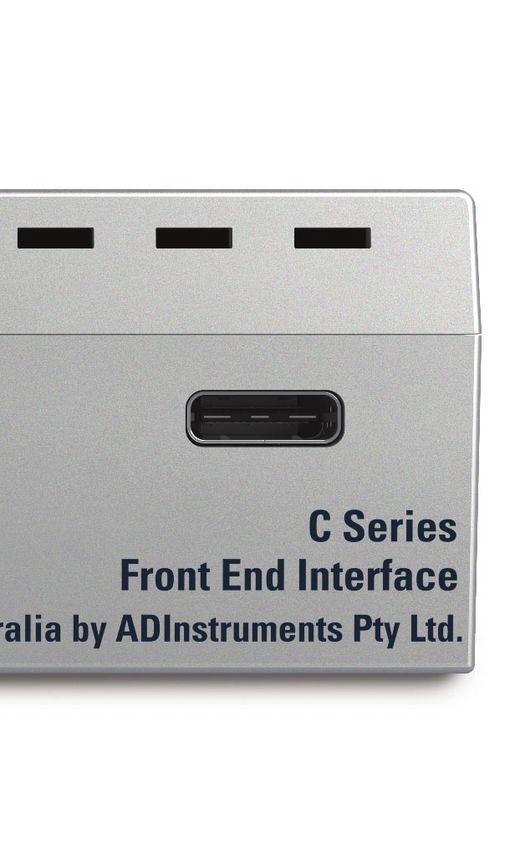
Chapter 1

    Safety Notes
    Statement of Intended Use
    All products manufactured by ADInstruments are intended for use in teaching and
    research applications and environments only. ADInstruments products are NOT
    intended to be used as medical devices or in medical environments. That is, no product
    supplied by ADInstruments is intended to be used to diagnose, treat or monitor a
    subject. Furthermore no product is intended for the prevention, curing or alleviation of
    disease, injury or handicap. ADInstruments products are intended to be installed, used
    and operated under the supervision of an appropriately qualified life-science researcher.
    The typical usage environment is a research or teaching lab or hospital. ADInstruments
    equipment is not intended for use in domestic environments.
    Where a product meets IEC 60601-1 it is under the principle that:
         • this is a more rigorous standard than other standards that could be chosen.
         • it provides a high safety level for subjects and operators.

    The choice to meet IEC 60601-1 is in no way to be interpreted to mean that a product:
         • is a medical device,
         • may be interpreted as a medical device, or
         • is safe to be used as a medical device.

    Safety and Quality Standards
    In accordance with European standards PowerLab C and C Series devices also comply
    with the electromagnetic compatibility requirements under EN61326-1, which
    encompasses the EMC directive.

    Quality Management System ISO 9001:2015
    ADInstruments manufactures products under a quality system certified as complying
    with ISO 9001:2015 by an accredited certification body.

1                                                                             Owner’s Guide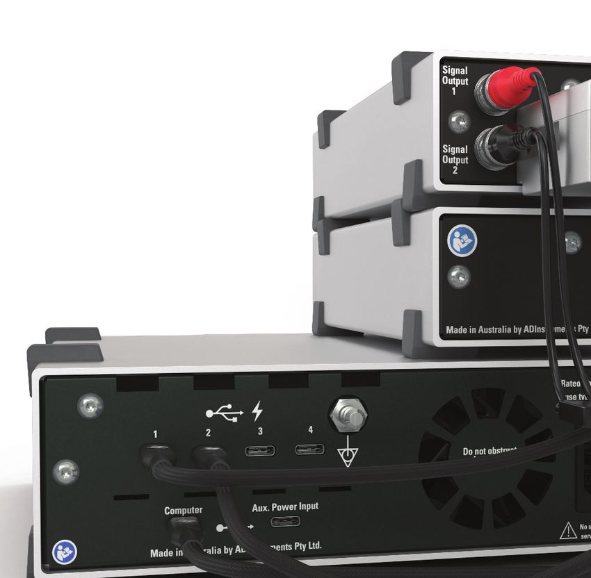
Regulatory Symbols
    Devices manufactured by ADInstruments that are designed for direct connection to
    humans and animals are tested to IEC60601-1:1998 and IEC60601-1:2005 (including
    amendments 1 and 2) and EN61326-1:2006, and carry one or more of the safety symbols
    below.

                       Warning symbol. The exclamation mark inside a triangle means that the
           !           supplied documentation must be consulted for operating, cautionary or
                       safety information before using the device.

                       CE Mark. All front-end amplifiers and PowerLab systems carry the CE
                       mark and meet the appropriate EU directives.

                       Refer to booklet symbol. This symbol specifies that the user needs
                       to refer to the Instruction manual or the booklet associated with the
                       device.

                       Date of Manufacture/ Manufacturer’s name symbol. This symbol
                       indicates the date of manufacture of the device and the name of the
                       manufacturer

                       WEEE directive symbol. Unwanted equipment bearing the Waste
                       Electrical and Electronic Equipment (WEEE) Directive symbol requires
                       separate waste collection. (See disposal section at the end of this
                       chapter)

    Further information is available on request.

    Safety Standards
    IEC Standard - International Standard - Medical Electrical Equipment
    IEC 60601-1:2012      General requirements for safety

2                                                                            Owner’s Guide
General Safety Instructions
               !         To achieve the optimal degree of subject and operator safety, consideration should be
                         given to the following guidelines when setting up a PowerLab C either as stand-alone
                         equipment or when using PowerLab equipment in conjunction with other equipment.
                         Failure to do so may compromise the inherent safety measures designed into PowerLab
          WARNING:       equipment.
                         The following guidelines are based on principles outlined in the international safety
   This equipment is     standard IEC 60601-1: General requirements for safety – Collateral standard: Safety
  not intended to be     requirements for medical systems. Reference to this standard is required when setting
modified or serviced     up a system for human connection. The user is responsible for ensuring any particular
          by the user.   configuration of equipment complies with IEC60601-1-1.
 No user serviceable
         parts inside.   The PowerLab C (and many other devices) requires the connection of a personal
   Refer servicing to    computer for operation. This personal computer should be certified as complying with
          authorized     IEC 60950 and should be located outside a 1.8 m radius from the subject (so that the
     ADInstruments       subject cannot touch it while connected to the system). Within this 1.8 m radius, only
      service center.    equipment complying with IEC 60601-1 should be present. Connecting a system in this
                         way obviates the provision of additional safety measures and the measurement of
                         leakage currents.
                         Accompanying documents for each piece of equipment in the system should be
                         thoroughly examined prior to connection of the system.
                         While it is not possible to cover all arrangements of equipment in a system, some
                         general guidelines for safe use of the equipment are presented below:
                             • Any electrical equipment which is located within the SUBJECT AREA should be
                               approved to IEC 60601-1.
                             • Do not touch the subject to which the PowerLab (or its peripherals) is connected
                               at the same time as making contact with parts of the PowerLab (or its peripherals)
                               that are not intended for contact to the subject.
                             • Cleaning and sterilization of equipment should be performed in accordance
                               with manufacturer’s instructions. The isolation barrier may be compromised if
                               manufacturer’s cleaning instructions are not followed.
                             • The ambient environment (such as the temperature and relative humidity) of the
                               system should be kept within the manufacturer’s specified range or the isolation
                               barrier may be compromised.
              !              • The entry of liquids into equipment may also compromise the isolation barrier. If
                               spillage occurs, ADInstruments should be contacted before using the equipment.
                             • The PowerLab depends on the presence of a Protective Earth for it’s electrical
                               safety requirement. This is usually provided from the power outlet through a
                               power cord. Before connecting the equipment to mains power, ensure that the
          WARNING:             power socket has a protective earth circuit capable of carrying the fault current
                               (see bullet point below). Note the POAG terminal on the rear of the PowerLab C is
 Use only with ADI             not rated as a Protective Earth.
   supplied power            • The Protective Earth must be cable of carrying the maximum current allowed by
 cords appropriate             the circuit breaker and must be electrically insulated. It must be connected to
   for your region.

      3                                                                                           Owner’s Guide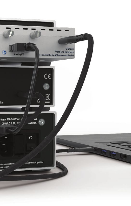
an equi-potential source (a metal stake drive into the soil is a typical situation). A
                                licensed electrician must perform this installation.
                            •   Power cords should never be modified so as to remove the earth connection. The
                                integrity of the Protective Earth connection between each piece of equipment
                                and the Protective Earth should be verified regularly by qualified personnel.
                            •   PowerLabs are compatible with electrical safety devices (sometimes known as
         WARNING:               Safety Switches, Ground fault circuit interruptor, Residual Current Devices or
    To avoid risk of            Earth-leakage Circuit Breaker). ADInstruments recommends the use of such
electric shock, this            devices supplied in fixed wiring installations.
  equipment must            •   Avoid using multiple portable socket-outlets (such as power boards) where
only be connected               possible as they provide an inherently less safe environment with respect to
 to a supply mains              electrical hazards. Individual connection of each piece of equipment to fixed
    with protective             mains socket-outlets is the preferred means of connection.
              earth         •   When used in ambient temperatures of 38 degrees Celcius and above, do not
                                touch PowerLab enclosure or the USB cable continuously for more than a minute.
                            •   To safely shut down the PowerLab, press the stop button and then close
                                LabChart. Turn the PowerLab off at the inlet switch.
                       If multiple portable socket outlets are used, they are subject to the following constraints:
                            • They shall not be placed on the floor.
                            • Additional multiple portable socket outlets or extension cords shall not be
                              connected to the system.
                            • They shall only be used for supplying power to equipment which is intended to
                              form part of the system.

                       Cleaning and Sterilization
                       ADInstruments products may be wiped down with a lint free cloth moistened with
                       industrial methylated spirit.

                       Inspection and Maintenance
                       PowerLab systems and ADInstruments front-ends are all maintenance-free and do
                       not require periodic calibration or adjustment to ensure safe operation. Internal
                       diagnostic software performs system checks during power up and will report errors if a
                       significant problem is found. There is no need to open the instrument for inspection or
                       maintenance, and doing so within the warranty period will void the warranty.
                       The PowerLab system can be periodically checked for basic safety by using an
                       appropriate safety testing device. Tests such as earth leakage, earth bond, insulation
                       resistance, subject leakage and auxiliary currents and power cable integrity can all be
                       performed on the PowerLab system without having to remove the covers. Follow the
                       instructions for the testing device if performing such tests. If the PowerLab system
                       is found not to comply with such testing you should contact your ADInstruments
                       representative to arrange for the equipment to be checked and serviced.

    4                                                                                                 Owner’s Guide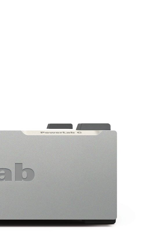
Environment
                 Electronic components are susceptible to corrosive substances and atmospheres, and
                 must be kept away from laboratory chemicals.

                 Transport and Storage Conditions
                     • Temperature in the range 0–40 °C
                     • Non-condensing humidity in the range 0–95%.

                 Operating Conditions
                     • Temperature in the range 5–35 °C
                     • Non-condensing humidity in the range 0–90%.

                 Disposal
                     • Forward to recycling center or return to manufacturer.
                     • Unwanted equipment bearing the Waste Electrical and Electronic Equipment
                       (WEEE) Directive symbol requires separate waste collection. For a product
                       labeled with this symbol, either forward to a recycling center or contact your
                       nearest ADInstruments representative for methods of disposal at the end of its
WEEE Directive         working life.
   symbol

5                                                                                     Owner’s Guide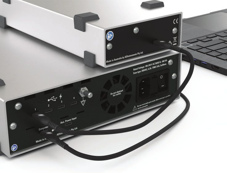
Chapter 2
Overview
The PowerLab C and C Series devices are ADInstruments’ range of modern, high
quality, research grade laboratory data acquisition hardware. They work seamlessly
with LabChart 8 and LabChart Lightning to provide a reliable foundation on which
to integrate a variety of input and output devices suitable for a range of life science
applications.
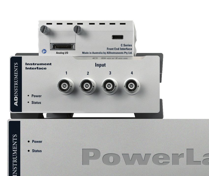
Figure 2–1
Front End Interface,
Instrument Interface
and PowerLab C
6 Owner’s GuideHow to Use This Guide
This owner’s guide describes how to set up and begin using the PowerLab C, the Front
End Interface and the Instrument Interface. The chapters provide an overview of the
entire system (the combined software and hardware package), and a more detailed
look at the features of each unit and its connections to other recording devices as well
as to your computer. There are also chapters that provide technical information and
solutions to problems. At the end of this guide is a glossary of hardware terms.
Software Installation
The ADInstruments application software should be installed before connecting or using
a PowerLab C or any C Series device.
The Getting Started with PowerLab manual provides full installation instructions for the
LabChart software.
PowerLab Check
Please do not attempt to connect a PowerLab C or any C Series device to a power outlet
or computer or turn it on until you have checked it as described below.
1. Check that all items in the accompanying packing list are included in the box.
2. Check that there are no obvious signs of external damage to the unit.
3. Check that there are no obvious signs of internal damage, such as rattling. Pick
up the unit, tilt it gently from side to side, and listen for anything that appears to
be loose.
If anything is missing or the unit seems to be damaged in any way, contact your
authorized ADInstruments representative immediately. Up to date contact addresses
are available from the ADInstruments website.
Connection information is in the next chapter.
7 Owner’s GuidePower-on Self Diagnostics
The PowerLab C and C Series devices perform a self test during power up. The software
will run a number of system checks to verify functionality of the internal circuitry. None
of these tests calibrate or change the performance of the devices in any way, they are
used only to determine the operability of the device.
Any faults found during this procedure may be indicated in two ways.
1. As long as USB communication is functional, errors may be reported by LabChart
when communication to the device is established.
2. The PowerLab will also give a Red status LED if the test detects a hardware fault.
The devices contain no user-serviceable parts inside. If a hardware fault is reported
by a PowerLab C or any C Series device, an ADInstruments representative should be
contacted.
8 Owner’s GuideChapter 3
Setting Up
This chapter describes:
• Connecting the Hardware.
• Installing the software
Figure 3-1
C Series
devices
connected
9 Owner’s GuideConnecting the Hardware
The PowerLab C and C Series devices use USB-C to communicate with either a host
computer, or a PowerLab C.
With a PowerLab C
The PowerLab C should be connected to the host computer using either the included
USB-C to USB-A cable, or the USB-C to USB-C cable depending on port availability. The
PowerLab C can be powered in one of 3 ways:
Figure 3-2
Connecting a
PowerLab C to a
computer with USB
• Using the included mains power cable: This is the recommended approach as it
! ensures that the system has its full 320W power budget available.
• Host-Powered: If the host computer supports the USB-PD standard on the USB-C
WARNING: port that the PowerLab is connected to the PowerLab can draw power directly
from the host computer. Note that the power budget of the downstream facing
Ensure the ports will be limited by the power available from the host computer.
PowerLab is • Auxiliary Power Input: A second power-only USB-C connector on the back of the
positioned away
PowerLab can be used to power it from a USB-PD compliant power supply, such
from any obstacles
(such as a wall)
as battery packs, laptop chargers or car chargers. Note that the power budget
that might of the downstream facing ports will be limited by the power available from the
prevent access to selected power supply.
the power switch
in the case of any Other C series devices (such as the Front End Interface) should be connected to the
emergency. downstream facing ports of the PowerLab C using the included USB-C to USB-C
Cable. This will provide both power and a data connection to the device.
10 Owner’s GuideWithout a PowerLab C
C Series devices can be connected directly to a host computer. Specific host requirements
are detailed in the following chapters. This configuration is only recommended if using
one C Series device. If using multiple devices a PowerLab C should be used.
Installing the Software
PowerLab C and C Series devices are compatible with both LabChart 8 software and
LabChart Lightning on both Windows and Mac.
LabChart 8
Install the latest version of LabChart 8 by visiting adi.to/powerlabcstart. Once installed
LabChart will automatically detect PowerLab C and C Series devices during it’s device
detection process. Getting started videos and more information can be found at the
link above.
LabChart Lightning
Install the latest version of LabChart Lightning by visiting adi.to/powerlabcstart. Once
installed LabChart Lightning will automatically detect PowerLab C and C Series devices.
Getting started videos and more information can also be found at the link above.
PowerLab Event Link (PEL)
A PowerLab C and all C Series devices can communicate with each other using a
proprietary protocol implemented on USB-C Alternate Mode which is named the
PowerLab Event Link (PEL). This allows these products to remain time synchronized and
will enable additional advanced device synchronization features in the future.
Using USB cables supplied by ADInstruments is recommended. If using 3rd party cables
with the PowerLab C or any C Series devices it is critical that cables used to connect
between them meet the following requirements:
• USB3.1 5Gbps or 10Gbps speeds
11 Owner’s GuideChapter 4
PowerLab C
The unit, together with a range of specialized application programs, provides a versatile
data recording and analysis system when used with a Windows or Macintosh computer.
This chapter provides an overview of the PowerLab® system and describes the basic
features, connectors and indicators of the PowerLab.
Note that the software supplied with the PowerLab should be installed before
connecting the PowerLab to the computer.
Figure 4–1
The PowerLab C
12 Owner’s GuideThe PowerLab C
! The PowerLab C provides 4 downstream-facing USB-C (with Power Delivery) ports for
connection to equipment with a USB-C interface (such as the Front-End Interface) and
provides 2 upstream-facing ports for connection to a computer supporting USB-C with
Power Delivery. The port marked “Computer” provides data and power connection
WARNING: from the host computer. The auxiliary port (marked “Aux. Power Input”) provides a
power-only input from an alternate power source. The auxiliary port may be useful in
The PowerLab applications where battery power is desired.
C is not
The PowerLab provides adaptive mains filtering (when powered via the mains) and also
intended as
provides advanced device synchronisation features.
diagnostic,
therapeutic or Multiple PowerLab Cs’ may be connected in series to provide extra ports if required.
patient care
equipment. Doing
so may result in
severe risk to the The Front Panel
safety of the Patient. The front panel (Figure 4–2) provides the indicators for various functions.
• The ‘Power’ LED illuminates as the following colours when the system is receiving
power from one of the 3 possible power sources
1. Blue - Mains power
2. Cyan - Auxillary port powered
3. Purple - Computer port powered
4. Also Amber - While initial booting. This remains on if the boot failed.
• The ‘Status’ LED indicates the current state of the device
1. Yellow - PowerLab is idle
2. Green - PowerLab is connected to LabChart
Power
Figure 4–2 indicator
The front panel
of the
PowerLab C
Power
Status
Status
indicator
13 Owner’s GuideThe Rear Panel
The rear panel of the PowerLab C (Figure 4-3) provides the sockets to connect the
PowerLab to the computer, other devices and the power outlet. This section describes
each of the rear panel features:
Figure 4–3
The rear panel
of the
PowerLab C
Downstream Computer Aux Power Ground Cooling Power switch and
facing Port Port Fan socker (with fuse
USB Ports drawer)
Upstream facing USB Ports
WARNING:
Upstream facing USB Ports
1. Computer Port: For connection to the host computer using either a USB-C to
PowerLab inputs USB-C Cable or a USB-C to USB-A Cable. The host computer requires only USB2.0
and outputs are to be compatible. If the host computer features a USB-C port that supports
not electrically USB-PD the PowerLab can also be powered using this port. Note that the power
isolated and so budget of the downstream facing ports will be limited by the power available
should never be from the host computer.
connected to 2. Aux Power Port: This port can optionally be used to power the PowerLab from a
human subjects.
USB-PD compliant power supply, such as battery packs, laptop chargers or car
chargers. Note that the power budget of the downstream facing ports will be
limited by the power available from the selected power supply.
Downstream facing USB Ports
The downstream facing ports are primarily intended for connection to any ADInstruments
C Series device. These devices should be connected using an ADInstruments supplied
USB-C to USB-C Cable. If using a third party cable it must support both alternate mode
and be capable of 100W USB-PD. Each of the 4 downstream facing ports functional
identically.
The downstream facing USB-C Ports do support standard USB-PD at up to 100W
(depending on how the PowerLab is itself powered) meaning it can be used as a power
source for other USB-PD compliant devices such as some laptops, tablets and mobile
phones.
Ground Connector
A special earthing stud is provided on the rear panel of the PowerLab. This is an
equipotential bonding connection post compatible with the DIN 42801 standard. It
14 Owner’s Guideis used as an equipotential connection point in situations that require this type of
connection or if there is no ground provided via the power cord. This connector is not
rated as a Protective Earth and should only be used to provide functional earthing.
Power Connector
The power switch on the back right of the PowerLab C turns the PowerLab on and
off; the 3-pin IEC power socket is used to connect the PowerLab to a power cable. The
power supply is universal, and can use all common international mains power supplies
(100–240 V AC, 50/60 Hz).
The PowerLab C is fitted with replaceable fuses. If the Power LED on the PowerLab, does
! not illuminate with power applied, it may be that one or both of the replaceable fuses
has blown. Fuses should only be of the rating and type as specified below:
• 250VAC Slo Blo (usually marked “T”)
• 6.3A
WARNING:
• 20 x 5mm
Ceramic replace-
ment fuses should Checking and replacing fuses
be used in Ensure the power lead is disconnected before attempting to replace a fuse.
preference to glass
fuses. Glass fuses The fuses are contained in the fuse drawer. To remove the drawer, the top and bottom
are fragile and are plastic tabs need to be squeezed simultaneously while pulling the drawer away from
prone to breakage, the PowerLab (a small flat-bladed tool is useful for this task). The old fuses should
potentially leading spring free of the drawer once removed from the inlet. Load the new fuses back into
to injury. the drawer and carefully push back into the inlet. Note that the fuse drawer is polarized
and can only be put back in one orientation. For further assistance please contact your
nearest ADInstruments representative.
Note: Fuse replacement should only be attempted by appropriately qualified service
personnel. If the fuse is suspected as blown, please contact ADI service representative
or appropriately qualified service personnel.
Figure 4–4
Removing and
replacing fuses
Fuses in fuse
drawer
15 Owner’s GuideUsing Multiple PowerLabs
Multiple PowerLab C units can be connected in one of two ways:
1. Daisy Chained: The ‘Computer’ port of the second PowerLab C is connected to
one of the downstream facing ports on the first PowerLab C. This allows the
second PowerLab to be powered by the first, allows full use of the PowerLab
Figure 4–5 Event Link (PEL) between devices but comes at the cost of using one of the
Daisy chained available downstream facing ports on the first PowerLab.
PowerLabs
! To
Computer
WARNING:
When used in
ambient
temperatures of 38
degrees and above,
do not touch
PowerLab enclosure
for more than a
minute
continuously.
2. Connect both PowerLabs to the host computer: This maximizes the number of
WARNING: downstream facing ports for other C Series devices but comes at the cost of
not allowing PEL communications between C Series devices connected to the
When used in different PowerLabs.
ambient
temperatures of 38
degrees and above,
do not touch
the USB cable for
more than a minute
continuously.
16 Owner’s GuideFigure 4–6
PowerLabs con-
nected to host
computer
Supplied Accessories
Accessory
MLAC89/2 USB-C to USB-C cable (1m)
MLAC89/3 USB-C to USB-A cable (1m)
17 Owner’s GuideChapter 5
Front End
Interface
The Front End Interface allows existing ADInstruments Front Ends with I2C and BNC
connectors to be connected to the PowerLab C. The Front End Interface provides
analog-to-digital conversion, USB-C/PD interface for connection to the PowerLab C and
FE device detection.
Figure 5–1
The Front End
Interface
18 Owner’s GuideThe Front End Interface
This section describes the connectors and indicators of the Front End Interface.
The Front View
Figure 5–2
The front view
of the
Front End
Interface
NOTE: I2C Port
The front of the Front End Interface (Figure 5–2) provides an I2C port for connection to
The Front End
any ADInstruments Front End. The product is designed to connect directly to the rear of
Interface does not
all current Front Ends. It can also be connected via the MLAC02 DB9M -DB9F Cable (sold
support daisy
separately) if required.
chaining Front Ends.
The ‘I2C Output’
port on a Front End
should NOT be used
in conjunction with
the Front End
Interface.
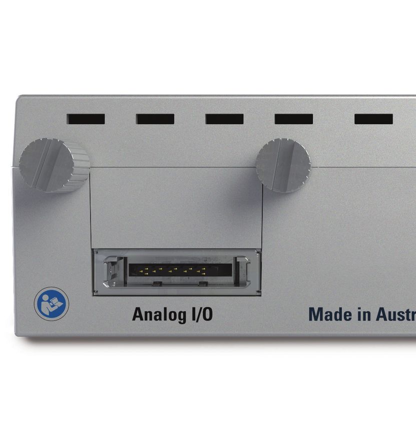
19 Owner’s GuideThe Rear View
The rear of the Front End Interface (Figure 5-3) has the following connectors/ features:
Guide Screws
Figure 5–3
The rear view of
the
Front End
Interface
Analog Input/ USB-C port
Output
Connector
NOTE: • USB-C Port for connection to PowerLab C or computer
• Analog connector for connection to the analog outputs on the rear of the front
The Front End End. 1, 2, 4 and 8 Channel cable variants are available. See the compatibility
Interface does not matrix below for details.
support daisy • Guide Screws for securely attaching to the rear of a supported ADInstruments
chaining Front Ends. Front End. These screws should be done up finger tight only. Note these screws
The ‘I2C Output’ are not necessary if connecting the device via an MLAC02 DB9 cable.
port on a Front End
should NOT be used
in conjunction with
the Front End
Interface.
20 Owner’s GuideAnalog Cable
There are 4 variants of the analog cable assembly.
• MLAC871 1 Channel Analog Cable
• MLAC872 2 Channel Analog Cable
• MLAC874 4 Channel Analog Cable
• MLAC878 8 Channel Analog Cable
When using a multi channel analog cable the connection order does not matter except
when using a device with a stimulator output. Please see the compatibility matrix
(Figure 5-11) at the end of the chapter for details.
Connecting a Front-End to the Front End Interface
A Front-End can be connected to the Front End Interface in the following ways:
1. Screwed directly using the guide screws: In this case, the I2C port on the front of
the Front End Interface can be inserted into the corresponding port on the rear
panel of the Front End. Once inserted, the guide screws on the Interface can be
twisted clockwise to to engage with the threads on the nuts of the serial port on
the Front- End.
2. Using a DB9M- DB9F cable: In this case, the MLAC02 DB9M - DB9F cable can be
used to connect the Front End to the Interface directly. This maybe required in
Figure 5–4
Direct
connection
NOTE:
The Front End
Interface does not
support daisy
chaining Front Ends.
The ‘I2C Output’
port on a Front End
should NOT be used the case of some older Front-Ends like the ML138 Octal Bio Amp.
in conjunction with
the Front End
Interface.
21 Owner’s GuideFigure 5–5
Connection
using a I2C cable
Connecting a Front-End into a system
A Front-End can be connected using the Front End Interface in the following ways:
1. Through a PowerLab C: After screwing the Front End Interface into the I2C port of
the Front End, the requisite Analog cable can be used to connect the two devices.
Using the USB-C to USB-C cable, the Interface can be powered by connecting it
to one of the 4 downstream facing USB ports on the PowerLab C. A USB-C to
USB-C cable or USB-C to USB-A cable should be used to connect the PowerLab
(using the ‘Computer’ labelled upstream facing port) to the appropriate USB
port on the computer .
2. Directly to the Computer: After connecting the Front-End and the Front End
Figure 5–6
Connecting a
Front End using
a PowerLab C
To
Computer
Interface using an analog cable, the Interface can be powered by directly
connecting it to a computer. In this case, an ADInstruments supplied USB-C
to USB-C cable must be used to connect the Interface to a USB-C port on the
22 Owner’s Guidecomputer. Please note that the USB port must be capable of delivering a
minimum of 15W of power.
Figure 5–7
Connecting a
Front End
directly to a
computer
To
Computer
Supplied Accessories
Accessory
MLAC89/1 USB-C to USB-C cable (300mm)
MLAC871 Analog Cable (1 Channel)
MLAC872 Analog Cable (2 Channels)
MLAC874 Analog Cable (4 Channels)
MLAC878 Analog Cable (8 Channels)
Software
LabChart 8:
Front End Interface devices will be detected and listed during LabChart 8’s device
detection process. Channels can be enabled in the ‘Devices and Channels’ dialogue in
the ‘Setup’ menu. There are no specific settings available for the Front End Interface
itself. All settings for the connected Front End can be found in the Input Amplifier
section of the channel drop down menu.
LabChart Lightning:
Front End Interface devices will be detected during LabChart Lightning’s device
detection process.
23 Owner’s GuideFront End Compatibility Table
Front End Supported Minimum Limitations Supported
Cable without
Figure 5–8 Requirement PowerLab C?
Front End ‘35 Series’ Front-Ends
Compatibility
Table
FE231 Bio Amp Yes 1 Channel Y (=>7.5W Port)
MLAC871
FE232 Dual Bio Yes 2 Channel Y (=>7.5W Port)
Amp
MLAC872
FE234 Quad Bio Yes 4 Channel Y (=> 15W Port)
Amp
MLAC874
FE238 Octal Bio Yes 8 Channel N
Amp
MLAC878
FE285 Neuro Yes 1 Channel Y (=>7.5W Port)
Amp MLAC871
FE221 Bridge Yes 1 Channel Y (=>7.5W Port)
Amp MLAC871
FE224 Quad Yes 4 Channel Y (=>7.5W Port)
Bridge Amp MLAC874
FE228 Octal Yes 8 Channel N
Bridge Amp MLAC878
FE117 BP Amp Yes 1 Channel Y (=>7.5W Port)
MLAC871
FE116 GSR Amp Yes 1 Channel Y (=>7.5W Port)
MLAC871
FE165 pH Amp Yes 2 Channel Y (=>7.5W Port)
MLAC872
FE305 Pod Yes 4 Channel Y (=> 15W Port)
Expander MLAC874
FE141 Yes 1 Channel Y (=>7.5W Port)
Spirometer MLAC871
FE180 Stimulus Yes 1 Channel If using a multi- Y (=>7.5W Port)
Isolator channel analog
MLAC871 cable the red
cable MUST be
used
FE155 Yes 1 Channel If using a multi- Y (=>7.5W Port)
channel analog
Stimulator HC MLAC871 cable the red
cable MUST be
used
24 Owner’s GuideFront End Supported Minimum Limitations Supported
Cable without
Requirement PowerLab C?
IN125/X NIBP Yes 2 Channel Trigger in/out not Y (=>7.5W Port)
Controller supported
MLAC872
IN175 STH Yes 1 Channel Y (=>7.5W Port)
Pump MLAC871
Controller
FE132 Bio Amp Yes 1 Channel Y (=>7.5W Port)
MLAC871
FE135 Dual Bio Yes 2 Channel Y (=>7.5W Port)
Amp
MLAC872
FE136 Animal Yes 1 Channel Y (=>7.5W Port)
Bio Amp MLAC871
FE185 Neuro Yes 1 Channel Y (=>7.5W Port)
Amp MLAC871
IN191 Blood NA - -
Flow Meter
‘30 Series’ Front-Ends
ML206 Gas Yes 2 Channel Y (=>7.5W Port)
Analyzer MLAC872
ML221 Bridge Yes 1 Channel Y (=>7.5W Port)
Amp MLAC871
ML224 Quad Yes 4 Channel Y (=> 15W Port)
Bridge Amp MLAC874
ML228 Octal Yes 8 Channel N
Bridge Amp MLAC878
ML117 BP Amp Yes 1 Channel Y (=>7.5W Port)
MLAC871
ML116 GSR Yes 1 Channel Y (=>7.5W Port)
Amp MLAC871
ML165 pH Amp Yes 2 Channel Y (=>7.5W Port)
MLAC872
ML305 Pod Yes 4 Channel Y (=> 15W Port)
Expander MLAC874
ML141 Yes 1 Channel Y (=>7.5W Port)
Spirometer MLAC871
ML142 GP Amp Yes 1 Channel Y (=>7.5W Port)
MLAC871
ML180 Stimulus Yes 1 Channel Y (=>7.5W Port)
Isolator
MLAC871
25 Owner’s GuideFront End Supported Minimum Limitations Supported
Cable without
Requirement PowerLab C?
ML155 Yes 1 Channel Y (=>7.5W Port)
Stimulator HC MLAC871
ML125/X NIBP Yes 2 Channel Y (=>7.5W Port)
Controller
MLAC872
ML175 Yes 1 Channel Y (=>7.5W Port)
STH Pump MLAC871
Controller
ML132 Bio Amp Yes 1 Channel Y (=>7.5W Port)
MLAC871
ML135 Dual Bio Yes 2 Channel Y (=>7.5W Port)
Amp
MLAC872
ML136 Animal Yes 1 Channel Y (=>7.5W Port)
Bio Amp MLAC871
ML138 Octal Yes 8 Channel N
Bio Amp MLAC878
ML185 Neuro Yes 1 Channel Y (=>7.5W Port)
Amp MLAC871
ML191 Blood Flow No - -
Meter
ML408 Dual Yes 4 Channel The red cable Y (=>7.5W Port)
MUST be used for
Bio/Stim MLAC874 connecting the
‘Stim’ connector
Older Front-Ends
ML205 Gas Yes - Does not use Front -
End Interface,
Analyzer uses Instrument
Interface
ML140 Yes 1 Channel Y (=>7.5W Port)
Spirometer MLAC871
ML110 Bridge Amp Yes 1 Channel Y (=>7.5W Port)
MLAC871
ML112 Quad Yes 4 Channel Y (=>7.5W Port)
Bridge MLAC874
Amp (wide
Bandwidth)
ML118 Quad Yes 4 Channel Y (=> 15W Port)
Bridge Amp MLAC874
ML119 Octal Yes 8 Channel N
Bridge Amp MLAC878
26 Owner’s GuideFront End Supported Minimum Limitations Supported
Cable without
Requirement PowerLab C?
ML160 No - -
Potentiostat
ML162 PicoStat No - -
ML164 No - -
QuadStat
ML130 Bio Amp No - -
ML133 Bio Amp No - -
(CF Rated)
27 Owner’s GuideChapter 6
Instrument
Interface
The Instrument Interface is a 4 channel device providing analog input capability to
the PowerLab C. The device is powered and controlled by a single USB-C/PD cable
connecting to the PowerLab C, or to a host computer. Connection to the PowerLab
C provides adaptive mains filtering (when PowerLab C is powered from mains) and
enables advanced synchronization features.
Figure 6–1
The Instrument
Interface
28 Owner’s GuideThe Instrument Interface
This section describes the connectors and indicators of the Instrument Interface.
The Front Panel
The front panel (Figure 6–2) provides the connectors and indicators for various
functions.
• The 4x BNC Input Ports for connection to analog instruments using a BNC-BNC
Cable.
• The ‘Power’ LED illuminates blue when the system is receiving power
• The ‘Status’ LED illuminates green when communication with LabChart has been
established.
Power
indicator
Figure 6–2
The front panel
of the
Instrument
1 2 3 4
Interface
Status BNC
indicator Ports
29 Owner’s GuideThe Rear Panel
The rear panel of the Instrument Interface is shown below (Figure 6-3).It provides the
USB-C Port for connection to the PowerLab C or computer.
Figure 6–3
The rear panel
of the
Instrument
Interface
USB-C
Port
Connecting an Analog Instrument into a system
An Analog Instrument can be connected using the Instrument Interface in the following
ways:
1. Through a PowerLab C: The Analog instrument can be connected to the
Instrument Interface by using the BNC sockets on the front panel. Using the
USB-C to USB-C cable, the Instrument Interface can be powered by connecting
it to one of the 4 downstream facing USB ports on the PowerLab C. A USB-C to
USB-C cable or USB-C to USB-A cable should be used to connect the PowerLab
(using the ‘Computer’ labelled upstream facing port) to the appropriate USB
port on the computer .
Figure 6–4
Connecting an
instrument to
the system using
a PowerLab C
To Computer
30 Owner’s Guide2. Directly to the Computer: After connecting the Analog instrument and the
Instrument Interface through the BNC sockets on the front panel, the Interface
can be powered by directly connecting it to a computer. In this case, an
ADInstruments supplied USB-C to USB-C cable or USB-C to USB-A cable can be
used depending on port availability on the computer.
Figure 6–5
Connecting an
instrument to a
computer
To
Computer
Supplied Accessories
Accessory
MLAC89/1 USB-C to USB-C cable (300mm)
MLAC89/3 USB-C to USB-C cable (1m)
Software
LabChart 8:
Instrument Interface devices will be detected and listed during LabChart 8’s device
detection process. Channels can be enabled in the ‘Devices and Channels’ dialogue
in the ‘Setup’ menu. Settings for the Instrument Interface can be found in the Input
Amplifier section of the channel drop down menu.
LabChart Lightning:
Instrument Interface devices will be detected during LabChart Lightning’s device
detection process.
31 Owner’s GuideInstrument Compatibility
The Instrument Interface is designed to work with most 3rd party instruments that
feature an analog output between -10V and +10V. Many instruments feature a BNC
output port, some may require an adapter cable.
32 Owner’s GuideChapter 7
Technical Specifications
This chapter describes some of the important technical aspects of the PowerLab C and
C Series devices. You do not need to know the material here to use these products. It
is likely to be of special interest to the technically minded, however it should not be
used as a service manual: user modification of the PowerLab voids your rights under
warranty.
Figure 7-1
Instrument Interface
connected to a laptop
through a PowerLab C
33 Owner’s GuideSpecifications
Common
USB Standards
PowerLab C and all C Series devices support
• USB2.0 Full speed data
• USB Type-C 1.2 and USB-PD version 3.0
• Proprietary PowerLab Event Link (PEL)
Regulatory Information
The PowerLab C and all C Series devices comply with the following
Safety: Complies with IEC 60601-1:2012 (tested by TÜV SÜD PSB,
Singapore)
Classification: Class I ME Equipment
EMC: Complies with IEC 60601-1-2:2014 (tested by TÜV SÜD
PSB, Singapore)
Operation: Continuous
Unsuitable uses: Do not use in the presence of flammable anaesthetic - air
mixtures. Avoid operating near high voltage, RF or strong
magnetic fields that may cause interference.
Method of Disposal: Forward to recycling center or return to manufacturer.
ADInstruments reserves the right to alter these specifications at any time.
34 Owner’s GuidePLC01 PowerLab C
Physical Configuration
Dimensions (h × w × d): 70 mm × 240 mm × 260 mm (2.8” × 9.4” × 10.2”)
Weight: 2.9 kg (6 lb 6 oz)
Operating Requirements
Operating voltage range: 100–240 V AC, 50/60 Hz
Rated Power: 400 VA
Earth Leakage Current:PLCF1 Front End Interface
Analog Inputs
Number of input channels: 8
Configuration: Single-ended
Amplification ranges: Range Resolution
± 10 V 313 µV
±5V 156 µV
±2V 62 µV
±1V 31 µV
± 500 mV 15 µV
± 200 mV 6 µV
± 50 mV 1.5 µV
± 20 mV 625 nV
Maximum input over-voltage: ± 13 V
Input impedance: 1 M
Input Coupling: DC
Non-linearity (max): 0.2 %
Low pass filters: Off, 20, 50, 100, 200, 500, 1000, 2000 Hz
(Only available when no front end device is detected)
Sampling
ADC sampling: Simultaneous across channels
ADC resolution: 18-bits (16-bit effective)
ADC linearity: ±4 LSB
Available sampling rates: Up to 100 000 samples/s per channel (max throughput
400 000 samples/s)
Output Amplifier
Number of output channels: 1
Maximum output current: 5 mA
Output rise time:Output impedance: 1 KΩ
Output level: 4.5 V
Physical Configuration
Dimensions (h × w × d): 27.5 mm x 68 mm x 88 mm (1.1” x 2.7” x 3.5”)
Weight: 0.1 kg (0 lb 4 oz)
Operating Requirements
Operating voltage range: 5 - 15 V
Rated Power: 15 W
Power requirements: Front-end dependent (Refer Figure 5 - 8)
Operating conditions: 5–35 °C, 0–90% humidity (non-condensing)
PLCI1 Instrument Interface
Analog Inputs
Number of input channels: 4
Configuration: Single-ended
Amplification ranges: Range Resolution
± 10 V 313 µV
±5V 156 µV
±2V 62 µV
±1V 31 µV
± 500 mV 15 µV
± 200 mV 6 µV
± 50 mV 1.5 µV
± 20 mV 625 nV
Maximum input over-voltage: ± 13 V
Input impedance: 1 M
Input Coupling: DC
Non-linearity (max): 0.2 %
37 Owner’s GuideFrequency response: 24K Hz (all ranges)
Crosstalk: >90 dB (unused channels 1K terminated)
Low pass filters: Off, 20, 50, 100, 200, 500, 1000, 2000 Hz
Sampling
ADC sampling: Simulaneous across channels
ADC resolution: 18-bits (16-bit effective)
ADC linearity: ±4 LSB
Available sampling rates: Upto 100 000 samples/s
Physical Configuration
Dimensions (h × w × d): 55 mm x 120 mm x 260 mm (2.2” x 4.7” x 10.2”)
Weight: 1.2 kg (2 lb 10 oz)
Operating Requirements
Operating voltage range: 5V
Rated Power:Electromagnetic Compatibility
The PowerLab C and C Series devices (the devices) have been tested to comply with IEC
60601-1-2:2014. The relevant basic EMC standards are IEC 61000-4-2, IEC 61000-4-3, IEC
61000-4-6, IEC 61000-4-8, IEC 61000-4-11 and CISPR 11.
Emissions
• The devices are suitable for use in all establishments other than domestic
and those directly connected to the public low-voltage power supply network
that supplies buildings used for domestic purposes. There may be potential
difficulties in ensuring electromagnetic compatibility in other environments, due
to conducted as well as radiated disturbances.
Immunity
• Mains power quality should be that of a typical commercial or hospital
environment. If the user of the device requires continued operation during
power mains interruptions, it is recommended that the device be powered from
an uninterruptible power supply or a battery.
• Power frequency magnetic fields should be at levels characteristic of a typical
location in a typical commercial or hospital environment.
• Floors should be wood, concrete or ceramic tile. If floors are covered with
synthetic material, the relative humidity should be at least 30%.
Separation Distances
• The devices are intended for use in an electromagnetic environment in which
radiated RF disturbances are controlled.
• Portable and mobile RF communications equipment should be used no closer
to any part of the device, including cables, than the recommended separation
distance in the table below.
• Field strengths from fixed RF transmitters, as determined by an electromagnetic
site survey, should be less than the compliance level in each frequency range.
Separation distance
Rated maximum output
150 kHz to 800 MHz 800 MHz to 2.7 GHz
power of transmitter, P
d = 1.17√P d = 2.33√P
0.01 W 0.1 m 0.2 m
0.1 W 0.4 m 0.7 m
1W 1.2 m 2.3 m
10 W 3.7 m 7.4 m
100 W 11.7 m 23.4 m
39 Owner’s GuideImmunity test IEC 60601 test level Compliance level Electromagnetic environment
guidance
Conducted RF 3 Vrms 3V Recommended separation
IEC 61000-4-6 150 kHz to 80 MHz distance
(see TableB–2 p. 50)
Radiated RF 3 V/m 3 V/m Recommended separation
IEC 61000-4-3 80 MHz to 2.7 GHz distance
(see TableB–2 p. 50)
Electrostatic discharge ±8 kV contact ±4 kV contact Floors should be wood,
IEC61000-4-2 ±15 kV air ±8 kV air concrete or ceramic tile.
If floors are covered with synthetic
material, the relative humidity
should be at least 30%.
Electrical fast transient/ ±2 kV for power supply ±2 kV for power supply Mains power quality
burst lines lines should be that of a typical
IEC61000-4-4 commercial or hospital
environment.
Surge ±0.5, 1 kV line-line ±0.5, 1 kV line-line Mains power quality
IEC 61000-4-5 ±0.5, 1, 2 kV line-ground ±0.5, 1, 2 kV line-ground should be that of a typical
commercial or hospital
environment.
Voltage dips, short 95 % dip in 95% dip in Mains power quality
interruptions and UT) for 0.5 cycle UT) for 0.5 cycle should be that of a typical
voltage variations commercial or hospital
on power supply 40% UT (60% dip in UT) 40% UT (60% dip in UT) environment. If the
input lines for 5 cycles for 5 cycles user of the devices
IEC61000-4-11 require continued operation
70% UT (30% dip in UT) 70% UT (30% dip in UT) during power mains
for 25 cycles for 25 cycles interruptions, it is recommended
that the devices
95% dip in be powered from an
UT) for 5 sec uninterruptible power
supply or a battery.
Power frequency 3 A/m 3 A/m Power frequency magnetic
(50/60Hz) magnetic fields should be at
field levels characteristic of a
IEC 61000-4-8 typical location in a typical
commercial or hospital
environment.
Table 7-1 Immunity Test compliance
40 Owner’s GuideGlossary
Adaptive mains filtering. An advanced signal processing technique that seeks to eliminate
noise originating from mains power.
ADC (analog-to-digital converter). A device that converts analog information into some
corresponding digital voltage or current.
amplitude. The maximum vertical distance of a periodic wave from the zero or mean position
about which the wave oscillates.
analog. Varying smoothly and continuously over a range. An analog signal varies continuously
over time, rather than changing in discrete steps.
applied part. A part which necessarily comes into physical contact with the subject during use.
BNC (bayonet nut connector). A type of cable or connector; a BNC-to-BNC cable connects two
BNC connectors.
bridge transducer. A type of transducer using a Wheatstone bridge circuit. In its basic form,
the bridge consists of four two-terminal elements (usually strain gauges) connected to form a
quadrilateral. An excitationacross the other.
connector. A plug, socket, jack or port used to connect one electronic device to another (via a
cable): a PowerLab to a computer, say.
CPU (central processing unit). A hardware device that performs logical and arithmetical
operations on data as specified in the instructions: the heart of most computers.
DAC (digital-to-analog converter). A device that converts digital information into some
corresponding analog voltage or current.
DC offset. The amount of DC (direct current) voltage present at the output of an amplifier when
zero voltage is applied to the input; or the amount of DC voltage present in a transducer in its
equilibrium state.
DFP. Downstream-Facing Port. A port that allows the connection of a peripheral such as a
front-end, mobile phone, etc.
filter. An electronic device or a program that alters data in accordance with specific criteria.
Filters in hardware and software can be used to reduce or to eliminate electronic noise or drift
from data readings.
frequency. The number of complete cycles per second of a waveform. Frequency is usually
expressed in hertz: Hz (cycles per second), kilohertz: kHz (thousands of cycles per second), or
megahertz: MHz (millions of cycles per second).
41 Owner’s Guidefrequency response. The bandwidth in which a circuit passes a signal without too much
attenuation. A low-pass filter’s frequency response is the frequency where the output voltage
becomes 0.707 (1/√2) of the input voltage or has been attenuated by 3 decibels. If a low-pass
filter has a frequency response of 200 Hz, say, then the signal is effectively unattenuated up to
150 Hz, and is 0.707 of the original value at 200 Hz.
front-end. An ancillary device that extends PowerLab capabilities, providing additional signal
conditioning and features for specialized work. Front-ends are recognized automatically by the
PowerLab system and seamlessly integrated into its applications, operating under full software
control.
gain. The amount of amplification of a signal.
I2C (‘eye-squared-sea’). This connection is used by the PowerLab to control front-ends. It
provides power and communications using a 4-wire serial bus (two wires for standard I2C and
two control lines).
IEC. International Electrotechnical Commission.
LabChart. An application supplied with a PowerLab that emulates a multi-channel chart
recorder, with other powerful options. (Macintosh and Windows versions differ slightly.)
PD. Power Delivery. An industry standard regulating the flow of power between devices which
use USB-C standard.
port. A socket where you plug in a cable for connection to a network or a peripheral device.
Also, any connection for transferring data, for instance between the CPU and main memory.
PowerLab Event Link (PEL). A communication protocol supported by USB-C which allows
vendor-defined data transmission between devices.
range. In LabChart and Scope, the range is the greatest positive and negative voltage that can
be displayed, usually from ±5 mV to ±10 V, in 11 steps. (Range is inversely proportional to gain,
the extent of amplification.)
transducer. A physical device that converts a mechanical, thermal or electrical stimulus into a
proportional electrical output. For example, there are common transducers to measure force,
displacement, temperature, pressure, and similar parameters.
UFP. Upstream-Facing Port. A port that is intended for connection of a controlling device such
as a computer.
USB. Universal Serial Bus.
USB-C. Universal Serial Bus with Type-C connector. An industry standard specifying providing
high-speed data and power.
waveform. The shape of a wave; a graph of a wave’s amplitude over time.
42 Owner’s GuideWarranty
Product Purchase and License Agreement
This Agreement is between ADInstruments NZ Ltd [‘ADI’] and the purchaser [‘the Purchaser’]
of any ADI product or solution — software, hardware or both — and covers all obligations and
liabilities on the part of ADI, the Purchaser, and other users of the product. The Purchaser (or
any user) accepts the terms of this Agreement by using the product or solution. Any changes to
this Agreement must be recorded in writing and have ADI’s and the Purchaser’s consent.
Responsibilities
The Purchaser and any others using any ADI product or solution agree to use it in a sensible
manner for purposes for which it is suited, and agree to take responsibility for their actions and
the results of their actions. If problems arise with an ADI product, ADI will make all reasonable
efforts to rectify them. This service may incur a charge, depending on the nature of the problems,
and is subject to the other conditions in this Agreement. ADI does not separately warrant the
performance of products, equipment or software manufactured by third parties which may be
provided to Purchaser as part of an overall solution. However, as further noted below, ADI will
pass through to Purchaser all applicable third party warranties to the extent it has the right to
do so.
ADI Product Hardware Warranty
ADI warrants that PowerLab Data Acquisition Units (PL prefix)1 and Front-ends (FEprefix)2 shall
be free from defects in materials and workmanship for five (5) years from the date of purchase.
Other PowerLab Data Acquisition Units3, Front-ends4 and Pods5 shall be free of defects in
material and workmanship for three (3) years from their date of purchase. ADI also warrants
that ADI Specialized Data Recorders6 and Instruments7 shall be free of defects in material and
workmanship for one (1) year from their date of purchase. If there is such a defect, as Purchaser’s
sole remedy hereunder, ADI will repair or replace the equipment as appropriate, and the duration
of the warranty shall be extended by the length of time needed for repair or replacement.
To obtain service under this warranty, the Purchaser must notify the nearest ADI office, or
Authorized Representative, of the defect before the warranty expires. The ADI or Representative
office will advise the Purchaser of the nearest service center address to which the Purchaser
must ship the defective product at his or her own expense. The product should be packed safely,
preferably in its original packaging. ADI will pay return shipping costs.
43 Owner’s GuideYou can also read