30 INCH FREESTANDING GAS RANGE - INSTALLATION GUIDE SPECIFICATIONS, INSTALLATION, AND MORE - Forno
←
→
Page content transcription
If your browser does not render page correctly, please read the page content below

30 INCH FREESTANDING GAS RANGE

      Conforms to ANSI STD Z21.1-2018 Certified to CSA STD 1.1-2018 Household Cooking Gas Appliances.

INSTALLATION GUIDE
SPECIFICATIONS, INSTALLATION, AND MORE

MODEL NUMBERS: FFSGS6275-30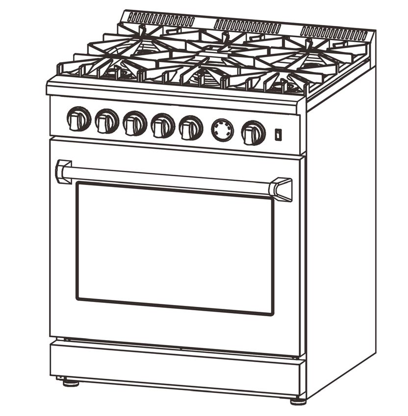
Index
Consumer information................................................................................................................................................................... 1
ANTI-TIP DEVICE ...................................................................................................................................................................... 2
IMPORTANT SAFETY INFORMATION .................................................................................................................................... 3
Features of Your Range................................................................................................................................................................. 7
INSTALLATION INSTRUCTIONS ............................................................................................................................................. 8
Cooktop Burner Grills Installation ................................................................................................................................................. 9
Handle installation guide ............................................................................................................................................................... 9
Electrical indication .....................................................................................................................................................................10
Electric Power Supply Requirements ............................................................................................................................................11
Gas Supply ..................................................................................................................................................................................11
Pressure regulator ........................................................................................................................................................................12
Gas Shut-off Valve ......................................................................................................................................................................12
Product Dimensions and Cabinets ................................................................................................................................................12
Exhaust Hood Installation ............................................................................................................................................................13
Gas Conversion Operation............................................................................................................................................................14
Gas Supply Connection ................................................................................................................................................................21
Cooktop Operation.......................................................................................................................................................................22
Oven Operation............................................................................................................................................................................23
Oven Cleaning Tips .....................................................................................................................................................................24
Steam clean..................................................................................................................................................................................24
Oven thermostat and temperature gauge .......................................................................................................................................25
Care and Maintenance Recommendations.....................................................................................................................................25
Troubleshooting Tips ...................................................................................................................................................................26
Wire diagram ...............................................................................................................................................................................27
Consumer information
                                                      Range Safety
                                Your safety and the safety of others are very important.
This cooking range Conforms to ANSI STD Z21.1-2018 Certified to CSA STD 1.1-2018 Household Cooking Gas Appliances.
We have provided many important safety messages in this manual and on your appliance. Always read and obey all safety
messages.
                             This is a safety alert symbol. It will alert you to potential personal or property safety hazards.
                             Obey all safety messages to avoid any property damage, personal injury or death.

    WARNING
                             Before using this cooker range, make sure to conduct leakage testing on all connections by
                             using soapy water solutions. Fail to do so may cause potential personal or property safety
                             hazards.

    WARNING
                             WARNING indicates a potentially hazardous situation which, if not avoided, could result in
                             serious injury or death.
                             CAUTION indicates a moderate hazardous situation which, if not avoided, could result in

    CAUTION
                             minor or moderate injury.
                             All safety messages will alert you what the potential hazard is, tell you how to reduce the
                             chance of injury, and let you know what can happen if the instructions are not followed.

    WARNING
If the information in this manual is not followed exactly, a fire or explosion may result, causing property
damage, personal injury or death.
Do not store or use gasoline or other flammable vapors and liquids in the vicinity of this or any other
appliance.

- WHAT TO DO IF YOU SMELL GAS
• Do not try to light any appliance.
• Do not touch any electrical switch.
• Do not use any phone in your building.
• Immediately call your gas supplier from a neighbor’s phone. Follow the gas supplier’s instructions.
• If you cannot reach your gas supplier, call the fire department.
Installation and service must be performed by a qualified installer, service agency or the gas supplier.

                                                               1
ANTI-TIP DEVICE
             WARNING
                         Tip-over Hazard
                         A Child or adult can tip the range which can result in serious injuries or death.
                         Install the anti-tip device to the range and/or structure per installation instructions.
                         Engage the range to the Anti-tip device installed to the structure.
                         Re-engage the anti-tip device if the range is removed.
                         Failure to follow these instructions can result in death or serious injuries and/or burns to children
                         and adults.
To reduce the risk of tipping the range, the range must be secured by properly installed anti-tip device packed with the
range. See installation instructions shipped with the bracket for complete details before attempting to install.
All ranges can tip and cause injuries.

Installing the anti-tip bracket
1. Drill 6 holes on the wall with correct sizes according to below table:
                                   Wall Type                Hole diameter
                            Wooden wall                           0.1”
                            Concrete wall                         0.31”

2. Please find the plastic sleeves in the part bag and put them inside the holes of the wall.

3. Please find the anti-tip plates in the part bag and fix them on the wall by the screws. Make sure the anti-tip bracket is
                                                              2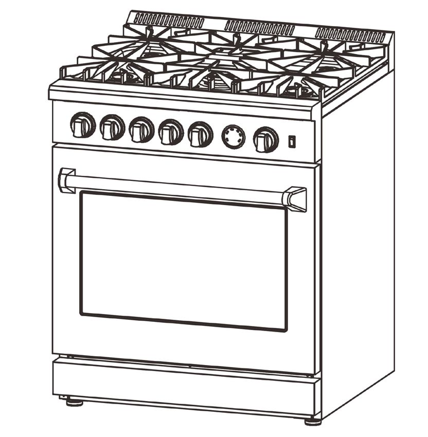
securely attached to the wall.

4. Slide the range forward to the anti-tip bracket, make sure the anti-tip bracket insert into two holes on the range back
panel.

                                                                        Range back panel

                         Anti-tip bracket

IMPORTANT SAFETY INFORMATION
READ ALL INSTRUCTIONS BEFORE USING THE APPLIANCE

    WARNING
                                     Read all safety instructions before using the product. Failure to follow these instructions
                                     may result in fire, electrical shock, serious injury or death.

GENERAL SAFETY INSTRUCTIONS
 WARNING
             NEVER use this appliance as a space heater to heat or warm the room. Doing so may
             result in carbon monoxide poisoning and overheating of the oven.
1. Use this range for its intended purpose as described in this instruction manual.
2. Have your range installed and properly grounded by a qualified installer in accordance with the provided installation
instructions.
3. Any adjustment and service should be performed only by a qualified gas range installer or service technician. Do not
attempt to repair or replace any part of your range unless it is specifically recommended in this manual.
4. Your range is shipped from the factory set for use with natural gas or propane (LP) gas. It can be converted for use with
either. If required, these adjustments must be made by a qualified technician in accordance with the installation instructions
and local codes. The agency performing this work assumes responsibility for the conversion.
5. Have the installer show you the location of the range gas shut-off valve and how to turn it off if necessary.
6. Plug your range into a 120 volt grounded outlet only. Do not removed the round grounding prong from the plug. If in
                                                                 3
doubt about the grounding of the home electrical system, it is your responsibility and obligation to have an ungrounded
outlet in accordance with the National Electrical Code. Do not use an extension code with this range.
7. Before performing any service, unplug the range or disconnect the power supply at the household distribution panel by
removing the fuse or switching off the circuit breaker.
8. Be sure all packing materials are removed from the range before operating to prevent ignition of these materials.
9. Avoid scratching or impacting glass displays. Doing so may lead to glass breakage. Do not cook on a product with broken
glass. Shock, fire, or cuts may occur.
10. Do not leave children alone or unattended in an area where an appliance is in use. They should never be allowed to
climb, sit or stand on any part of the range.

11.     CAUTION Do not store items of interest to children in cabinets above an oven-children who climb onto
the oven to reach items could be seriously injured.
12. Never block the vents (air openings) of the range. They provide the air inlets and outlets that are necessary for the range
to operate properly with correct combustion. Air openings are located at the rear of the cooktop, at the top and bottom of
the oven door, and at the bottom of the range.
13. Use only dry pot holders--moist or damp pot holders on hot surfaces may result in burns from steam. Do not let pot
holders touch surface burners, burner grate, or oven heating element. Do not use a towel or other bulky fabrics in place of
pot holders.
14. Do not touch the heating elements or the interior surface of the oven. These surfaces may be hot enough to burn even
though they are dark in color. During and after use, do not touch, or let clothing or other flammable materials contact any
interior area of the oven; allow sufficient time for cooling first. Other surfaces of the appliance may become hot enough to
cause burns. Potentially hot surfaces include the burners, grates, oven vent opening, surfaces near the opening, crevices
around the oven door, metal trim parts above the door, any back guard, or high shelf surface.
15. Do not heat unopened food containers. Pressure could build up and the container could burst, causing any injury.

      WARNING
Extremely Heavy.
Proper equipment and adequate manpower are needed when move the range to avoid personal injury or damage to the
unit or the floor.
Failure to follow this advice may result in damage or personal injury.

      WARNING
DO NOT carry or lift the cooking range by holding the oven door handle or the control panel!

               CORRECT                                   INCORRECT                                   INCORRET

      WARNING
                                                               4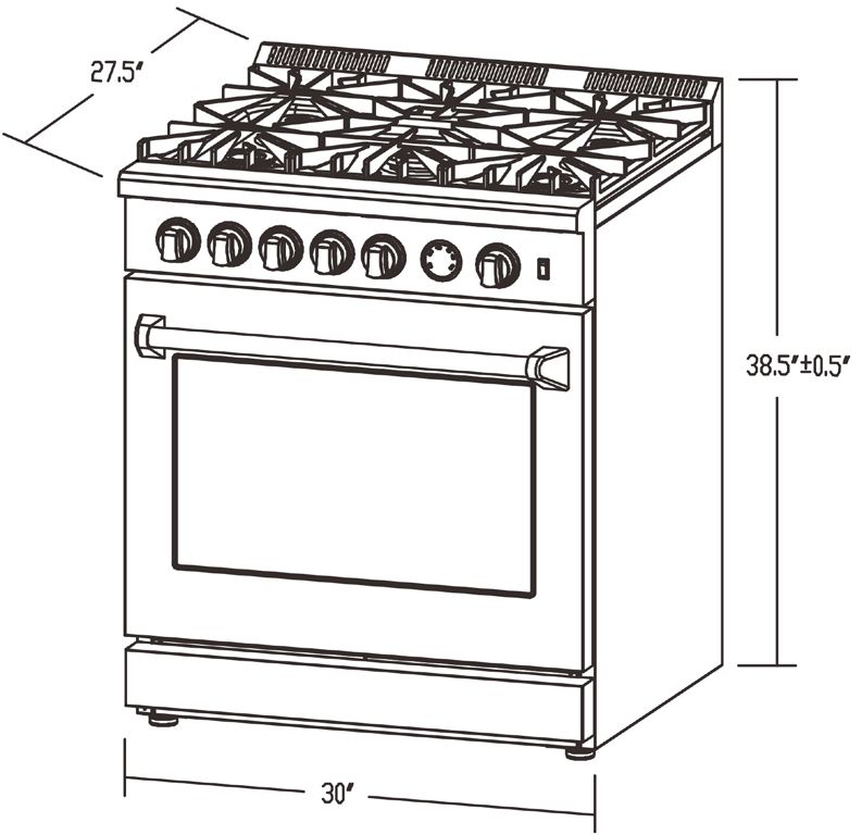
Cook food thoroughly to help protect against foodborne illness. Minimum safe food temperature recommendations can be
found at www.IsItDoneYet.gov and www.fsis.usda.gov. Use a food thermometer to take food temperatures and check
several locations.
Do not allow anyone to climb, stand or hang on the oven door, drawer or cooktop. They could damage the range or tip it
over causing severe injury or death.
Keep the ventilator hood and grease filter clean to maintain good venting and to avoid grease fires. Turn the ventilator OFF
in case of a fire or when intentionally "flaming" liquor or other spirits on the cooktop. The blower if in operation, could
spread the flames.

    WARNING                     KEEP FLAMMABLE MATERIAL AWAY FROM THE RANGE
Failure to do so may result in fire or personal injury.
Do not store or use flammable materials in an oven or near the cooktop, including paper, plastic, pot holders, linens, wall
coverings, curtains, drapes and gasoline or other flammable vapors and liquids.
Never wear loose-fitting or hanging garments while using the appliance. These garments may ignite if they contact hot
surfaces causing severe burns.
Do not let cooking grease or other flammable materials accumulate in or near the range.
Grease in the oven or on the cooktop may ignite.

    WARNING                     IN THE EVENT OF A FIRE, TAKE THE FOLLOWING STEP TO
PREVENT INJURY AND FIRE SPREADING.
Do not use water on grease fires. Never pick up a flaming pan. Turn the controls off. Smother a flaming pan on a surface unit
by covering the pan completely with a well-fitting lid, cookie sheet or flat tray. Use a multi-purpose dry chemical or
foam-type fire extinguisher.
If there is a fire in the oven during baking, smother the fire by closing the oven door and turning the oven off or by using a
multi-purpose dry chemical or foam-type fire extinguisher.
If there is a fire in the oven during self-clean, turn the oven off and wait for the fire to go out.
Failure to follow this instruction may result in severe burns.

    WARNING                     COOKTOP SAFETY INSTRUCTIONS
Never leave the surface burners unattended at medium or high heat settings. Foods, especially oily foods, may ignite
resulting in fire that could spread to surrounding cabinets.
Never leave oil unattended while frying. If allowed to heat beyond its smoking point, oil may ignite resulting in fire that may
spread to surrounding cabinets. Use a deep fat thermometer whenever possible to monitor oil temperature.
To avoid oil spillover and fire, use the minimum amount of oil when frying in a shallow pan and avoid cooking frozen foods
with excessive amounts of ice.
Use proper pan size and avoid pans that are unstable or easily tipped. Select cookware that matches the size of the burner.
Burner flames should be adjusted so that they do not extend beyond the bottom of the pan. Excessive flames may be
hazardous.
When using glass/ceramic cookware, make sure it is suitable for cooktop use; others may break because of a sudden change
in temperature.
To minimize the possibility of burns, ignition of flammable materials and spillage, cookware handles should be turned
toward the center of the range without extending over nearby burners.
                                                               5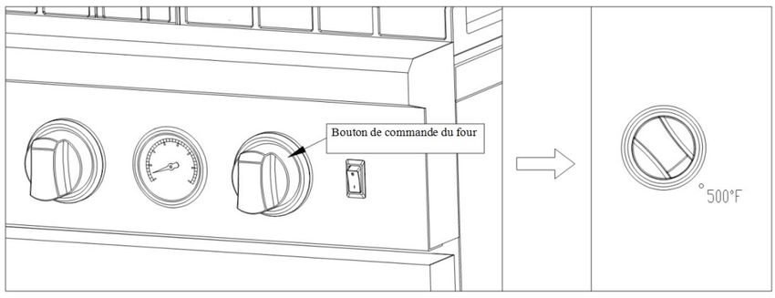
Do not use a wok with a round metal support ring. The ring may trap heat and block air to the burner resulting in a carbon
monoxide hazard.
Do not attempt to lift the cooktop. Doing so may damage the gas tubing to the surface burners resulting in a gas leak and
risk of fire.
Do not use aluminum foil to cover the grills or line any part of the cooktop. Doing so may result in carbon monoxide
poisoning, overheating of the cooktop surfaces, or a potential fire hazard.

    WARNING                     OVEN SAFETY INSTRUCTIONS
NEVER cover any slots, holes, or passages in the oven bottom or cover an entire rack with materials such as aluminum foil or
oven liners. Doing so blocks air flow through the oven and may cause carbon monoxide poisoning. Never place foil or oven
liners on the oven bottom. They can trap heat causing risk of smoke or fire. Stand away from the range when opening the
oven door. Escaping hot air or steam can cause burns to hands, face and/or eyes.
Never place cooking utensils, pizza or baking stones, or any type of foil or liner on the oven floor.
These items can trap heat or melt, resulting in damage to the product and risk of shock, smoke or fire.
Place oven racks in desired location while oven is cool. If the rack must be moved while the oven is hot, be careful to avoid
touching hot surfaces.
Do not leave items such as paper, cooking utensils, or food in the oven when not in use. Items stored in an oven can ignite.
Do not leave items on the cooktop near the oven vent. Items may overheat resulting in a risk of fire or burns.
Never broil with the door open. Open-door broiling is not advised due to overheating of control knobs.

    WARNING
This product can expose you to chemicals including carbon monoxide, which is known to the State of
California to cause developmental harm. For more information go to www.P65Warnings.ca.gov
To minimize exposure to these substances. Always operate this unit according the Owner’s Manual, and
ensure that you provide proper ventilation.

    WARNING
The installation must conform with local codes or, in the absence of local codes, with the National Fuel Gas Code,
ANSI Z223.1/NFPA 54 or, in Canada, the Natural Gas and Propane Installation Code, CSA B149.1."
& below label:

                                                     Warning
Never operate the top surface cooking section of the appliance unattended
Failure to follow this warning statement may result in fire, explosion or burn hazard that could cause property damage,
personal injury or death.
If a fire should occur, keep away from the appliance and immediately call your fire department.
DO NOT ATTEND TO EXTINGUISH AN OIL/GREASE FIRE WITH WATER

    WARNING
For fast exhausting the smell of "burning" or "oily" odor emitting from a new oven, turn the oven knob to
"Broil" and run for 30 minutes before first use.

                                                              6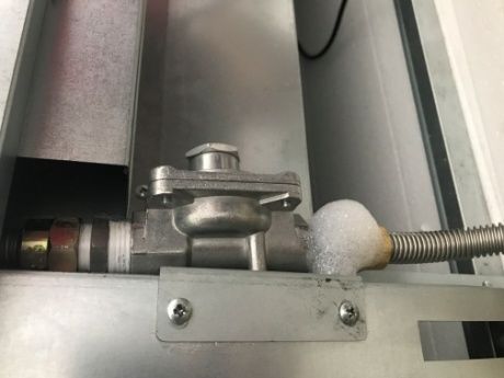
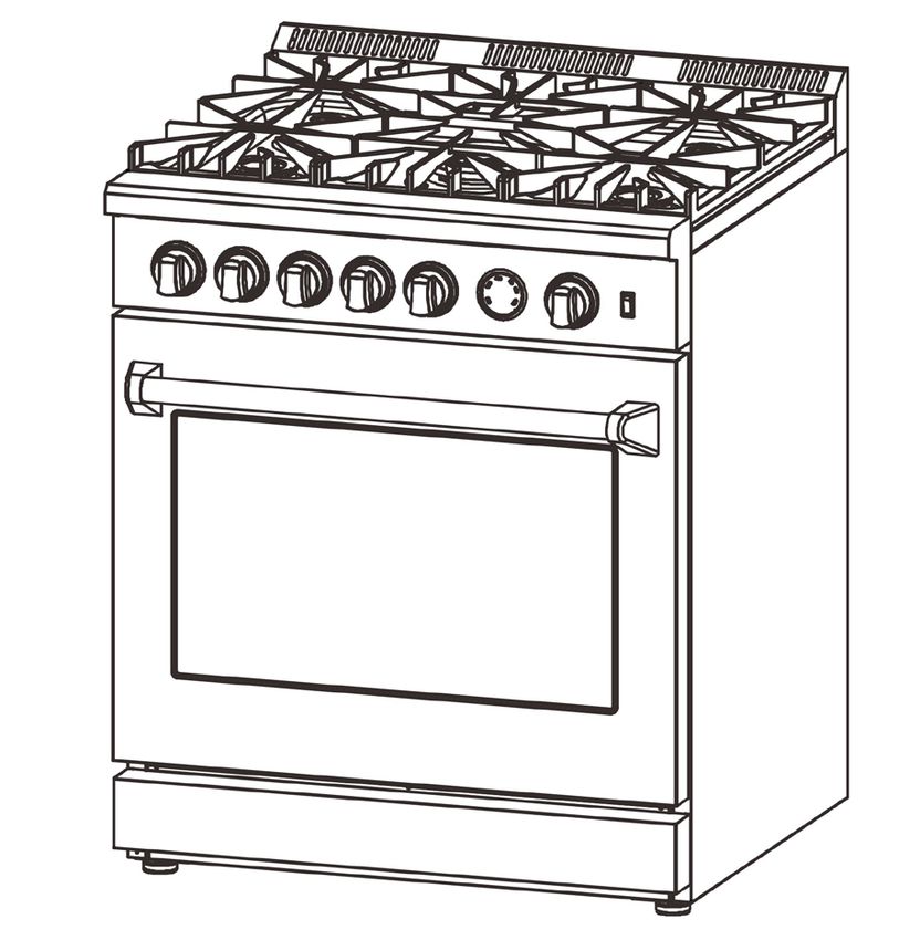
Features of Your Range

                   FFSGS6275-30 (5 BURNERS)

                                        1     Cooktop Burner Grill
                                        2     Control Panel
                                        3     Cooktop Control Knob
                                        4     Door handle
                                        5     Oven door
                                        6     Leveling System (legs)
                                        7     Oven Vents
                                        8     Oven Lights Switch
                                        9     Oven Control Knob
                                        10    Temperature gauge
                                        11    Kick Panel

                              7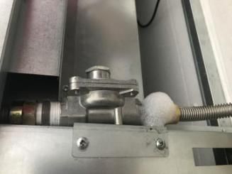
INSTALLATION INSTRUCTIONS
Before using your range
1. Remove all packaging material.
2. Check to make sure you have all of the accessories listed in below table.
                                               LPG injectors:
                                               1 piece 0.5;
                                               2 pieces 0.85;
                                               2 pieces 1.18;                                 1 package
                                               2 pieces 0.9;
                                               1 piece 1.18;
                                               1 piece 0.95.

                                               Anti-tip bracket, plastic sleeves and screws   1 set

                                               Left & right grills                            1 set

                                               Middle Grill                                   1 piece

                                               Oven door handle and screws                    1 set

                                               Burner & Cap (9500BTU)                         2 sets

                                               Burner & Cap (16000BTU)                        2 sets

                                               Burner & Cap (19000BTU)                        1 set

                                               Regulator (pre-installed)                      1 piece

                                               Serial Number Sticker & Instruction Manual     1 set

                                                                8
TOOLS NEEDED FOR INSTALLATION (not supplied with the range)
Tape measure
Screwdriver Wrench Socket wrench Allen key
&Pencil
Adjustable
Protective gloves Hammer Drill
wrench Adjustable pliers
Cooktop Burner Grills Installation
Remove the packing materials from the cooktop burner grills.
Place the burner grills to the correct position.
Handle installation guide
Step 1: Take out the door handle from the package.
Step 2: Take out four nuts from left and right on the door as illustrated in the pic.
Remove
Remove
Step 3: Position the handle onto the door at correct direction as illustrated in the pic. Make sure the 4 bolts can be
screwed into the holes underneath handle bases at two ends. Tighten the lower screws at two ends first from the inside
of oven door by using screw driver. Then tighten the two upper screws.
9Assemble the lower screws first
Step 4: Check the handle to make sure it is installed correctly and tightly as illustration.
WARNING:
The installation should be finished step by step. DO NOT remove the washer on the screws at the outside of oven door.
Electrical indication
Your range must be electrically grounded in accordance with local codes or, in the absence of local codes, in accordance
with the National Electrical Code (ANSI/NFPA 70, latest edition). In Canada, electrical grounding must be in accordance with
the current CSA C22.1 Canadian Electrical Code Part 1 and/or local codes.
The power supply must be the correct polarity. Reverse polarity will result in continuous sparking of the electrodes, even
after flame ignition. If there is any doubt as to whether the power supply has the correct polarity or grounded, have it
checked by a qualified electrician.
ELECTRICAL REQUIREMENTS
Electrical Supply Grounded, 110/120V AC, 60 Hz
Service 15 amp or 20 amp dedicated circuit
Receptacle 3-prong grounding-type
Power Cord 3.61' (1.1 m)
WARNING
Electrical grounding Instructions: This range is equipped with a three-prong (grounding) plug for your
protection against shock hazard and should be plugged directly into a properly grounded three-prong receptacle.
Do not cut or remove the grounding pin from the plug.
1CAUTION
Label all wires prior to disconnection when servicing controls. Wiring errors can cause improper and dangerous operation.
Verify proper operation after servicing.
ELECTRICAL SHOCK HAZARD
Disconnect electrical power at the circuit breaker box or fuse box before installing the appliance. Provide appropriate
ground for the appliance. Use copper conductors only. Failure to follow these instructions could result in serious injury or
death.
Electric Power Supply Requirements
Area allows for flush installation
with through-the-wall connection
of pipe stub/shut-off valve and
rear wall 120V outlet.
Shortest connection from hard pipe stub Area allows for flush installation with through-the-floor
location to range hook-up. connection of pipe stub/shut-off valve
Gas Supply
Installation must comply with local codes or, in the absence of local codes, with the National Fuel Gas Code, ANSI Z223.1 /
NFPA 54. In Canada, installation must conform to the current natural Gas Installation /code, CAN 1-1.1-M81 and with local
codes where applicable.
This range has been design-certified according to ANSI Z21.1b-2012 latest edition.
TYPE OF GAS:
NATURAL GAS WC
Supply Pressure 4"
Minimum Supply Pressure 6"
Max Regulator Pressure 14", 0.5 psi (3.5 kPa)
LP GAS WC
Supply Pressure 10"
Minimum Supply Pressure 11"
Max Regulator Pressure 14", 0.5 psi (3.5 kPa)
WARNING
Do not obstruct the flow of combustion air into the range and ventilation air away from the range
1Ventilation: it is recommended that the unit be operated with an oven head, vented exhaust hood of sufficient size and
capacity.
Pressure regulator
Since service pressure may fluctuate with local demand, every gas cooking range must be equipped with a pressure
regulator on the incoming service line for safe and efficient operation.
The pressure regulator shipped with the range has female threads 1/2" NPT. The regulator shall be installed properly in
order to be accessible when the appliance is installed in its final position.
Pressure regulator can withstand a maximum input pressure of 0.5 psi (3.5 kPa), and is
set at 4" WC outlet pressure.
Gas Shut-off Valve (not included)
shut-off valve at open position
Connect to Gas supply
The supply line must be equipped with an approved external gas shut-off valve located near the range in an accessible
location. Do not block access to the shut-off valve. Refer to the illustration below.
A 3/4" (19mm) ID gas supply line must be provided to the range. If local codes permit, a certified, 3' (900mm) long, 1/2"
(13mm) or 3/4" (19mm) ID flexible metal appliance connector is recommended to connect the unit’s 1/2" NPT female inlet
to the gas supply line. Pipe joint compounds suitable for use with natural or LP gas should be used.
The appliance and its shut-off valve must be disconnected from the gas supply piping system during any pressure testing of
the system at test pressures in excess of 0.5 psi (3.5 kPa). The appliance must be isolated from the gas supply piping system
by closing its individual manual shutoff valve during any pressure testing of the system at test pressures equal to or less
than 0.5 psi (3.5 kPa).
Product Dimensions and Cabinets
This range may be installed directly adjacent to existing countertop-height cabinets (36" or 91 cm from the floor). To achieve
the best look, the cooktop should be level with the cabinet countertop. This can be accomplished by raising the unit using
the adjustment spindles on the legs.
1Opening width
Front edge of
the range side
To countertops
panel forward
below cooktop
from cabinet
and at the range
back
Opening width W
30" Model 30" (762mm)
Exhaust Hood Installation
The bottom of the hood should be 30" min. to 36" above the countertop. This would typically result in the bottom of the
hood being 66" to 72" above the floor. These dimensions provide safe and efficient operation of the hood.
After Installation:
1. Check ignition of cooktop burners.
2. Check the air shutter adjustment – sharp blue flame, with no yellow tipping or lifting flames.
3. Check ignition of oven burner.
4. Visually check tubular burner (oven burner) re-ignition to be sure both rows of burner ports are relighting each time.
5. Check for gas leaks at all gas connections (using a gas detector, never a flame).
6. Check oven broil and convection bake function.
1Gas Conversion Operation
This cooking range can be used with LP gas and NG gas. It is shipped from the factory adjusted for use with NG(Nature Gas).
Injector for LP gas are included. Follow the instruction shown below for gas conversion.
WARNING Gas conversion shall be conducted by a factory- trained professional. Call the customer service
hotline to identify a factory-trained professional near your home.
WARNING Before carrying out this operation, disconnect the range from gas and electricity. Fail to do so,
may result in fire, or electrical shock hazard can occur and result in injury or death. Do not remove regulator or allow it to
turn during servicing.
The gas conversion procedure for this range includes 7 steps:
1. Pressure regulator 5. Reconnect Gas and Electrical Supply
2. Cooktop burners 6. Installation of new rating label
3. Oven burner 7. Gas Valve Adjustment (Optional operation)
4. Broil burner
The conversion is not completed if all 7 steps have not been concluded properly.
Before performing the gas conversion, locate the package containing the replacement injectors shipped with every range.
WARNING Before carrying out this operation, disconnect the range from gas and electricity. Fail to do so,
may result in fire, or electrical shock hazard can occur and result in injury or death. Do not remove regulator or allow it to
turn during servicing.
STEP 1: Pressure Regulator
To access the gas regulator, pull the range away from the cabinet wall. The gas regulator is located at the bottom right
corner of the range.
a. Unscrew the cap from the regulator. Do not remove the spring from the regulator.
b. Unscrew the white insert from the cap and turn it over so the longer stem is facing the cap. Replace insert on the cap.
Replace the cap on the regulator.
1Position for NG
Position for LPG
STEP 2: Cooktop Burners
a. Remove cooking grills and burner caps.
b. Lift off outer burner spreader.
c. Remove the factory installed natural gas nozzles from the center of the nozzle holders
using a 7mm socket wrench. Replace the LP injector in each nozzle holder. Tighten each
injector properly. Do not to over tighten the injector. Socket wrench
CAUTION Handle carefully when removing and replacing gas components. Use proper support to prevent
damage to components.
IMPORTANT: Each injector has a number indicating its flow diameter printed on the body. Consult the table below for
matching nozzles with cooktop burners.
CAUTION The Re-ignition system and automatic gas-cut-off system are not equipped on the cooktop
burners. If the flame goes out by accident, need to turn off the valve immediately to cut off the gas supply.
19500BTU 9500BTU
NG: 1.45 NG: 1.45
LPG: 0.9 LPG: 0.9
19000BTU
NG:1.4*2 (outer)+0.8(inner)
LPG: 0.85*2(outer)+0.5(inner)
16000BTU 16000BTU
NG: 2.0 NG: 2.0
LPG: 1.18 LPG: 1.18
STEP 3: Broiler Burner (up burner inside the oven)
Broil
Back cover plate
Oven
1unscrew
Tighten
Broil
unscrews LPG injector Ø0.95
Broil
unscrew
Tighten screws
A. Unscrew to open the back cover.
B. Use the open wrench to remove the screws from pipe connector.
C. Take out the 0.95 LPG injector from the part bag and replace the pre-install 1.6 NG injector.
D. Loosen the screws and adjust the diameter of the air inlet hole to 0.24”
E. Tighten the pipe connector and the gas inlet by screws.
1Injector diameter for broiler burners:
NG ---1.6 LPG --- 0.95
STEP 4: Oven Burner (bottom burner of the oven)
Oven
Rear cover bar
unscrews
Unscrew
Tighten
unscrew
LPG injector Ø1.18
1oven
Rear cover bar
Tighten screws
Back cover plate
Tighten screws
A. Open the rear cover bar by removing the screws.
B. Use the open wrench to remove the screws from pipe connector.
C. Take out the 1.18 LPG injector from the part bag and replace the 2.0 NG injector by the 1.18 LPG injector.
D. Loosen the screws and adjust the diameter of the air inlet hole to 0.32”
E. Fix the pipe connector and the gas inlet by the screws.
F. Fix the rear cover bar by the screws
G. Install the back cover plate by the screws
Injector diameter for oven burners: Back cover plate
NG ---2.0 LPG --- 1.18
IMPORTANT: Keep the injectors removed from the range for future use.
STEP 5: Reconnect Gas and Electrical Supply
1Leakage testing of the range shall be conducted according to the installation instructions provided with the range.
Before operating the range after the gas conversion, always check for leaks with a soapy water solution or other
acceptable method at gas connections installed between the gas inlet pipe of the range, gas regulator, and the manual
shut-off valve.
WARNING DO NOT use a flame to check for gas leakage.
WARNING Please make sure the thermocouple within 2-2.5mm far away from the oven burner.
Otherwise, the thermocouple may not touch the small flame at the minimum level, which will cause the flame out
accidentally.
STEP 6: Installation of LPG Conversion Label
Record the model and serial number on the LP / Propane Conversion Label provided in this kit.
The information can be obtained from the existing Rating / Serial label. Place the LPG conversion label as close as possible
to the existing Rating / Serial label on the range.
STEP 7: Gas Valve Adjustment (Optional operation)
If the oven burner flame is too big or too small, adjusting gas inlet orifice on the oven valve can be conducted to
correct the flame size. Follow the instructions in this section.
WARNING If the orifice is adjusted to be too small, the oven burner flame might be off during normal use.
Need to re-adjust the orifice in case this is happened.
Oven control
2Regulating screw
A. Turn oven control knob to 500F position, pull out the knob to access the regulating screw on the valve.
B. Use screwdriver to adjust the regulating screw. Turning anti-clockwise for larger flame size and clockwise till the end for
smaller flame size.
C. Put back the knob. Test it and repeat above steps until the oven burner flame is perfect.
Preparation
Before moving the range, protect any finished flooring and secure oven door(s) closed to prevent damage.
The oven door(s) can be removed to lighten the load or to fit the unit through a doorway. Only remove if necessary. Do not
remove the griddle or any other component. Door removal should only be done by a certified installer or service technician.
Placement
Do not lift or carry the oven door by the door handle.
Use an appliance dolly to move the range near the opening. Remove and recycle packing materials. Do not discard the
anti-tip bracket supplied with the range.
Leveling
Raise the range to the desired height by adjusting the legs. The legs can be adjusted by rotating clockwise to raise or
counter clockwise to lower the rang.
Anti-Tip Bracket
To prevent the range from tipping forward, the anti-tip bracket must be installed. Refer to the section of ANTI-TIP DEVICE.
Gas Supply Connection
All connections to the gas piping must be wrench-tightened. Do not over-tighten or allow pipes to turn when tightening.
When all connections have been made, check that all range controls are in the “OFF” position and turn on the main gas
supply valve.
If a flexible metal connector is being used, verify it is not kinked, then attach the gas supply line to the regulator on the
range. Open the valve and check for leakage by placing a liquid detergent solution onto all gas connections. Bubbles around
connections indicate a gas leak. If a leakage is determined, close the shut-off valve and fix the connections.
Leakage testing of the appliance shall be conducted according to the manufacture’s instructions . Use some soap water
(50% water and 50% soap) or a leakage detector at all joints and connections to check for leaks in the system. Do not use a
flame to check for gas leaks.
The appliance must be isolated from the building’s gas supply piping system by closing its individual manual shut-off valve
2during any pressure testing of the gas supply piping system at test pressure equal to or less than 0.5 psi (3.5kPa).
Getting Started
Before you start cooking, please take the following steps.
• Remove all the exterior and interior packing.
• Remove the protective film on steel and aluminum parts.
• Clean the range thoroughly with hot water and a mild detergent. Rinse and dry with a soft cloth to remove any residual oil
and grease left over from the manufacturing process.
• Check that surface burner components are assembled correctly.
• Furnish the interior of the oven by inserting the shelves and tray.
Cooktop Operation
The burner assembly contains all accessories in one set. The burner cap must be seated
Burner
on the burner horizontally. Refer to the illustration.
igniter
Burner
Ignition
To light up the cooktop burners, push the appropriate control knob in and turn counter clockwise to “ ” position. You will
hear clicking noise – the sound of electric spark igniting the burner. When one burner is turned to “ ”, all burners will spark.
Sparking will continue until the knob is not pressed, turn the knob to adjust desired flame intensity.
The knob pointing to “ ” is at the maximum fire level. Turning the knob to upside or downside can achieve smaller fire.
When the knob is turned to OFF position, the range will stop working and the valve will be shut down.
NOTE: Do not attempt to disassemble or clean around any burner while another burner is on. Do not touch any burner cap,
burner base, or igniter while the igniters are sparking.
CAUTION Never leave pans on a high setting unattended. Be careful when cooking food in fat or grease; it
can become hot enough to ignite.
Small and big flame:
A smaller flame will give the best results when simmering. Small flames offer precise cooking performance for delicate
foods, keeping food warm, melting chocolate or butter, and for cooking over low heat for long period of time.
The highest (larger) flame settings provide the maximum heat that is available on your range. This setting should be used for
heavy cooking jobs such as boiling water and cooking pasts.
Flame intensity
• When you adjust the flame intensity, watch the flame when you turn the knob.
• Any flame exceeding the bottom of the cookware is wasted.
• The flame should stay steady and blue in color. Impurity in the gas supply may cause an orange flame during initial
operation.
Power Failure
• If the gas does not ignite within four seconds, turn off the valve and allow at least five minutes for any gas to dissipate.
Repeat the lighting procedure.
2• In the event of a power failure, the surface burners can be lighted manually. Hold a lighted match near a burner and turn
the knob counter-clockwise to “ ”. After burner lights, turn knob to the desired setting.
Burner Grills
1. The grills must be properly positioned before cooking. Improper installation of the grills may result in scratching of the
cooktop and / or poor combustion.
2. Do not operate the burners without a pan or utensil on the grills.
CAUTION The surface of the grill is hot after use. Please allow sufficient time for the grill to cool before
cleaning.
Cooptop cleaning tips
• To prevent the cooktop from discoloring or staining, clean cooktop after each use, and wipe up acidic or sugary spills as
soon as the cooktop is cooled.
• The sealed burners of your range are not secured to the cooktop and are designed to be removed easily. Boil overs or
spills will not seep underneath the cooktop. The burners should be cleaned after each use.
Oven Light
The oven light is controlled by a push switch on the control panel.
The light can be used while cooking or cleaning the oven.
WARNING Before replacing the oven light, make sure power is disconnected from the electrical box and
the oven is cooled completely. Disassemble the light cover and replace the light bulb with a 25-watt halogen bulb. Install
the light cover properly.
Oven Operation
Oven Ignition
The oven is equipped with an ignition system which contains safety device. To light up the oven burners, push in the oven
control knob and turn anti-clockwise to reach 250˚F position or turn clockwise to “Broil” position and hold it. You will hear
clicking noise – the sound of electric spark igniting the burner, all burners will spark. Sparking will continue until once the
knob is released. Hold the knob until you can see the burner is lighted up.
DO NOT release the knob before you can see the flame comes up.
If fail to light up the oven burner within 4 seconds, reset the oven control knob to the OFF position, repeat above operations
until the oven burner is properly ignited.
WARNING:If fail to light up the oven burner 3 times continuously, the oven might full of the gas, then open the oven
door to allow gas dissipating before operating ignition again. Otherwise, the oven may explode and the user will get hurt.
IMPORTANT: Safety device is equipped with the oven burner. When the flame goes off by accident, the gas supply will be
shut off automatically. You need to turn the control knob back to the OFF position and ignite again.
Ignition system
When the flame is on,release the knob,the sparking will stop.
2Oven Baking Tips
1. Never cover any slots, holes or passages in the oven bottom or cover an entire rack with materials such as aluminum foil.
Doing so blocks air flow through the oven and may cause carbon monoxide poisoning. The aluminum foil lining may also
trap heat, causing a fire hazard.
Do not use aluminum foil on any porcelain surface. Doing so will damage the porcelain and affect its durability.
2. Position the racks before preheating the oven.
Preheating
Allow the oven to preheat before placing food in the oven. Preheating is necessary for good results when baking cakes,
cookies, pastry and breads.
The oven fan will be automatically switched on when the bottom burner is working. For fast preheating, turn the oven knob
to the “Broil” position. Wait for the oven to become hot, approximately for 3 minutes.
Note: Condensation or fogging on the inside of glass of the oven door is normal while preheating and it will evaporate by
the end of the preheating.
Oven Function
Natural Airflow Bake occurs when heat is transferred into the oven from the bake burners in the bottom of the oven cavity.
Heat is then circulated by natural airflow.This is a traditional bake setting.
Convection Bake
The oven fan will be switched on when the bottom burner is working. Heat is transferred to all over the inside of oven cavity.
It provides a more even heat distribution inside the oven than regular cooking.
Convection Roast
The convection fan circulates the heat evenly over and around the food. Heat will be circulated over the food being roasted.
Broiler Operation
Note: Door must be closed during broiling operation.
The broil burner is located at the top of the oven. As broiling is done with the oven door closed, it is normal to add some
smoke flavor to the food.
Setting Broil
Turn the oven control knob clockwise to select the Broil feature. When broiling, heat radiates downward from the
oven broiler. The temperature of Broil feature is 500˚F (260˚C).
Oven Cleaning Tips
1. After each use, and once the oven is cooled, clean splatters and spills immediately.
2. Do not allow foods with a high sugar or acid content to remain on the oven cavity surface.
3. Use an oven cleaner to clean the oven cavity.
4. Please use soft sabe to clean to clean up the enamel cooktop and enamel oven chamber.
Steam clean
In order for easy cleaning, you may add maximum 200ml water to the groove of the fireproof plate at the bottom of oven
cavity, DO NOT exceed the groove. Switch on the oven to heat up and generate steam all over the oven to soften the dirt
attached to the cavity for easy cleaning.
2Oven thermostat and temperature gauge
Thermostat is equipped in the oven, when the oven temperature reaches the setting, the thermostat will keep the oven
temperature stay relatively stable. Actual oven temperature can be read from the gauge on the control panel.
WARNING If the temperature of the gauge is not correctly matching with your setting when the cooker is
working for a period, please contact your local professional technicians to check. The user is NOT allowed to break up the
stove and adjust the oven thermostat directly.
Care and Maintenance Recommendations
Stainless steel Use non-abrasive stainless steel cleaner, apply small amount to a soft cloth, slightly wipe the
stainless steel surface, then towel dry. When wiping on the stainless steel surface, always follow
the grain of the metal.
Burner grills Clean with hot water and mild detergent or paste of baking soda and water. Do not immerse in
Oven rack guides water. Towel dry.
Burner pan Remove surface debris before cleaning to help speed up the process and decrease the chance of
scratching the surface during cleaning. Using mild abrasive cleaners or spray degreasers, clean and
rinse the surface and dry immediately. To clean hard water stains, use white vinegar and water.
Rinse and dry immediately.
Cooktop burners After cool down, use mild detergent or spray degreaser to clean. Rinse with water and towel dry.
Control knobs Using a damp cloth, wipe with a mild detergent or spray degreaser; rinse and dry. Do not place in
dishwasher.
Oven interior Use mild abrasive cleaners, spray degreasers. Use a razor blade to gently remove baked on foods
from oven cavity and window. For stubborn stains, spray with a mild abrasive cleaner or spray
degreaser. Clean the entire oven cavity with soap and water.
Pan To clean the pan, discard grease and wash with hot water and mild detergent. Rinse and dry.
2Troubleshooting Tips
Before you call for service
Range does not operate Check that power is on.
Check that electrical power to range and home circuit breaker is on.
Burners Do Not Light Or Spark Electrical plug is not connected properly with a live power outlet.
Randomly Gas supply not turned on.
Burner parts not replaced correctly.
Holes in the simmer rings or slits in the burner rings are clogged.
Clogged nozzles, or wet burners or electrodes.
A fuse in your home may be blown or circuit breaker tripped.
Burners Have Yellow Or Burner parts not replaced correctly.
Yellow-Tipped Flames A. Yellow flames: Call for service.
B. Yellow tips on outer cones: Normal for propane (LP) gas.
C. Soft blue flames: Normal for natural gas.
If burner flames look like (A), call for service.
Normal burner flames should look like (B) or (C), depending on
the type of gas.
Burner Flames Very Large Or The range may be connected to the wrong fuel type. Contact the person who installed
Yellow your range or made the conversion.
Burner Flames Contain Orange Airborne dust; cool-mist humidifier; debris on or inside burner.
Flickers
Oven Lights Do Not Work The light bulb is defective. Replace the bulb.
Oven Racks Are Hard To Slide Do not use a cooking spray or other lubricant sprays to make it smooth.
Refer to oven racks cleaning in the Care and Maintenance section.
Food Does Not Bake Or Roast The oven controls are improperly set. See the Baking or Roasting section.
Properly Oven not preheated for enough time.
Incorrect cookware or cookware of improper size being used.
Racks in the wrong position. See the Baking or Roasting section.
Use a foil tent to slow down browning during roasting.
Oven thermostat needs adjustment: Please contact the local professional technicians.
Food Does Not Broil Properly This model is designed for closed door broiling only. Always broil with the door closed.
The oven controls are not set at BROIL. See the Broiling section.
Improper rack position.
Cookware is not suited for broiling.
Aluminum foil used on the broiling pan and rack has not been fitted properly and slit as
recommended.
Oven Temperature Too Hot Or Oven thermostat needs adjustment. Please contact the local professional technicians.
Too Cold
Steam From The Vent When using the convection mode, it is normal to see steam coming out of the oven vent.
As the number of racks or amount of food being cooked increases, the amount of visible
steam will increase.
Burning Or Oily Odor Emitting This is normal in a new oven and will disappear in some time.
From The Vent
2Strong Odor This is temporary. An odour caused by the insulation around the inside of the oven is
normal for the first few times the oven is used.
Convection Fan Not On All The Please contact the local professional technicians.
Time
Condensation Or Fogging On Condensation or fogging on the glass of inside of oven door is normal during the
The Glass of inside of Oven preheating of the oven and will evaporate usually by the end of the preheating cycle.
Door.
Cracking Or Popping Sound This is normal. This is the sound of the metal heating and cooling during both the cooking
During Cleaning and cleaning functions.
Excessive Smoking Occurs The oven is heavily soiled. Turn the oven control knob to OFF. Open the windows to
During Cleaning exhaust. Wait until the oven is completely cooled. Wipe up excess soil and do the
cleaning again.
Closing the door caused the When the oven temperature reach the setting temperature, the flame inside the oven will
oven flame out accidentally be small. Closing the door at the minimum flame will cause the flame out accidentally.
Please make sure the small flame is going to be bigger before you close the door (no
more than 60s)
Wire diagram
FFSGS6275-30
Caution: Label all wires prior to disconnection when servicing controls. Wiring errors can cause improper and
dangerous operation. Verify proper operation after servicing.
2CUISINIÈRE À GAZ AMOVIBLE DE 30 POUCES
Conforme à la norme ANSI Z21.1-2018. Homologué conformément à la norme CSA1.1-2018. Appareils de cuisson à gaz domestiques.
GUIDE D'INSTALLATION
SPÉCIFICATIONS, INSTALLATION ET PLUS
NUMÉROS DE: FFSGS6275-30
2Contenu
INFORMATION POUR LE CLIENT ...................................................................................................................................................30
Dispositif anti-basculement ..........................................................................................................................................................30
Installation du support anti-basculement .....................................................................................................................................31
CONSIGNES DE SÉCURITÉ ...........................................................................................................................................................32
Fonctionnalités de la cuisinière ....................................................................................................................................................36
Consignes d’installation................................................................................................................................................................37
Installation des grilles de brûleur de la table de cuisson................................................................................................................38
Installation de la poignée de porte ...............................................................................................................................................38
Indication électrique ....................................................................................................................................................................39
Exigences de l’alimentation électrique .........................................................................................................................................40
Alimentation en gaz .....................................................................................................................................................................40
Vanne d'arrêt de gaz (non fournie) ...............................................................................................................................................41
Dimensions du produit et des armoires ........................................................................................................................................42
Installation de la hotte d’aspiration ..............................................................................................................................................43
Opération de conversion de gaz ...................................................................................................................................................43
Raccord à l'alimentation en gaz ....................................................................................................................................................50
Fonctionnement de la table de cuisson ........................................................................................................................................50
Fonctionnement du four ..............................................................................................................................................................52
Conseils de nettoyage du four ......................................................................................................................................................53
Nettoyage à la vapeur ..................................................................................................................................................................53
Thermostat du four et indicateur de température ........................................................................................................................54
Recommandations d'entretien et de nettoyage ............................................................................................................................54
Conseils de dépannage.................................................................................................................................................................55
Diagramme de câblage.................................................................................................................................................................55
29INFORMATION POUR LE CLIENT
Sécurité de la cuisinière
Votre sécurité et celle d’autres personnes sont très importantes.
Cette cuisinière est conforme à la norme ANSI STD Z21.1-2018 et est homologuée CSA STD
1.1-2018 pour les électroménagers de cuisson à gaz.
De nombreux messages de sécurité importants ont été fournis dans ce guide et sur votre
appareil. Lisez et
Il s’agit d’un symbole d'alerte de sécurité qui vous avertira des dangers potentiels de sécurité des personnes
ou des biens. Respectez tous les messages de sécurité pour éviter tout dommage matériel, blessure
corporelle ou la mort.
Avant d'utiliser cette cuisinière, assurez-vous d'effectuer des tests de fuite sur
toutes les connexions en utilisant des solutions d'eau savonneuse. Ne pas le
AVERTISSEMENT faire peut entraîner des risques potentiels pour la sécurité des personnes ou des
biens.
L’AVERTISSEMENT indique une situation potentiellement dangereuse qui, si elle
AVERTISSEMENT n'est pas évitée, pourrait causer des blessures graves ou mortelles.
LA MISE EN GARDE indique une situation de danger modéré qui, si elle n'est pas
évitée, pourrait entraîner des blessures mineures ou modérées.
MISE EN GARDE Tous les messages de sécurité vous alerteront du danger potentiel et le moyen
de réduire les risques de blessure et vous indiqueront ce qui peut se produire si
les consignes ne sont pas suivies.
AVERTISSEME
Si les informations contenues dans ce guide ne sont pas suivies à la lettre, un incendie ou une explosion peuvent se
produire et causer des dommages matériels, des blessures graves même mortelles.
N’entreposez pas et n’utilisez pas d’essence ou d’autres vapeurs et liquides inflammables près de cet appareil ou de tout
autre appareil.
-QUE DEVEZ- VOUS FAIRE SI VOUS SENTEZ UNE ODEUR DE GAZ
• • N'essayez pas d'activer un appareil quel qui soit.
• Ne touchez à aucun interrupteur électrique.
• N'utilisez aucun téléphone se trouvant dans votre immeuble.
• Appelez immédiatement votre fournisseur de gaz en utilisant le téléphone d’un voisin. Suivez les consignes du fournisseur
de gaz
• Si vous ne pouvez pas accéder à votre fournisseur de gaz, appelez le service d'incendie.
L’installation et le service doivent être effectués par un installateur qualifié, un centre de service ou le fournisseur de gaz.
Dispositif anti-basculement
AVERTISSEMENT
Risque de basculement
Un enfant ou un adulte peut faire basculer la cuisinière et cela peut causer des
blessures graves ou mortelles.
Installez le dispositif anti-basculement sur la cuisinière et/ou la structure
conformément aux consignes d'installation.
Engagez la cuisinière sur le dispositif anti-basculement installé sur la structure.
Si la cuisinière est retirée, réengagez le dispositif anti-basculement.
Si ces précautions ne sont pas respectées, la mort ou les blessures graves et/ou des
brûlures peuvent survenir chez les enfants et les adultes.
30La cuisinière doit être sécurisée à l'aide d'un dispositif anti-basculement correctement installé et fourni avec la
cuisinière afin de réduire son risque de basculement. Reportez-vous aux consignes d'installation fournies avec
la fixation pour obtenir toute les précisions avant de commencer l'installation. Toutes les cuisinières peuvent
basculer et causer des blessures.
Installation du support anti-basculement
4. Percez 6 trous sur le mur avec les tailles correctes selon le tableau ci-dessous:
Type de mur Diamètre du trou
Mur en bois 0.1”
Mur en béton 0.31”
5. Veuillez trouver les manchons en plastique dans le sac de pièces et les mettre dans les trous du mur.
3. Veuillez trouver les plaques anti-basculement dans le sac de pièces et les fixer au mur à l'aide des vis.
Assurez-vous que le support antibasculement est solidement fixé au mur.
4. Faites glisser la cuisinière vers l'avant sur le support anti-bascule, assurez-vous que le support anti-bascule
s'insère dans deux trous sur le panneau arrière de la cuisinière.
31You can also read