3rd Project Phase Elaboration and Materialisation - PROCESS GUIDELINES Prepared by Niccolò Becattini - ELPID
←
→
Page content transcription
If your browser does not render page correctly, please read the page content below
PROCESS GUIDELINES
3rd Project Phase Elaboration
and Materialisation

Prepared by Niccolò Becattini

May, 2019
3rd Project Phase
Elaboration and Materialisation
Characteristics that requirements and the specification should comply with

                              Niccolò Becattini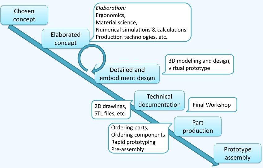
Where we were, are and will be
Initial Phase (1)
Product Development Process
Fuzzy Front End Project
Definition and Vision
Conceptual Phase (2)
Conceptual Design and
Early Embodiment
of the solution Solution
Concept(s)
Elaboration and
Materialization Phase (3)
Late embodiment and Detail
Design of the solution Virtual
Prototype of the solution,
simulation and documentation
Evaluation Phase (4)
Workshop for final solution
refinement and estimation
of its potential
Elaboration and Materialisation Phase

Deliverables and Deadlines
• Report: May 23rd
    • Max 10000 words
• 3D CAD files: May 23rd
    • Parts
    • Sub-Assemblies
    • Complete Assembly
• Simulation Files: May 23rd
    • Motion study
    • Static analysis
• Bill of Materials: May 23rd
• Draft of the whole solution (not drafts/drawings of sub-assemblies or parts) and exploded view: May 23rd
• Renders: Optional for phase 3, to be done compulsorily in Ljubljana)

                                               3 Weeks
                         Duration of this phase:

                         Next Review Meeting: May 27
                                                     th

                         Consolidation Meeting: May 30
                                                      th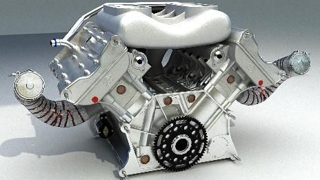
Expectations for 3rd project review

Concept Refinement                                                Mechanical               Consolidation of the
                                 Parts & Assembly
    (e.g. combination of                                           Behaviour                  solution and
                                     Modeling
solutions, definition of sub-
                                 (Tasks to be distributed
                                                                  assessment                 Documentation
           systems)                                         (Simulations for parts, sub-   (Finalization of 3D models,
                                   among all the team
           +                    members, according to the   assemblies, final assembly.      Report, Bill of Materials,
                                                            E.g. FEM, Kinematic and/or     File Structure, Render, Cost
      Gantt Chart                       planning)
                                                               Dynamic Analyses...)                 analysis…)

     May 6th-10th                   May 9th-20th                  May 15th-23th                May 18th-26th

                     Note: Despite this is displayed as a sequential process, dates show that
            overlaps and iterations might be necessary for fine tuning the solution and documenting it
Concept Refinement
                     1. Reconsider the concept which was selected
                        as the most promising during the 2nd
                        review meeting
                     2. Apply/propose the required modification
                        as highlighted by the company
                        representative
                     3. Start planning a general layout for your
                        solution
                         • Where will the subsystems be placed?
                         • How much room do they need?
                     4. Check for existing components that should
                        not be produced from scratch and that are
                        available in the market
                         • Check for existing 3D models to
                             import
                         • Check the toolbox/shop of
                             components embedded in your CAD
                             modelling system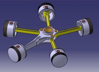
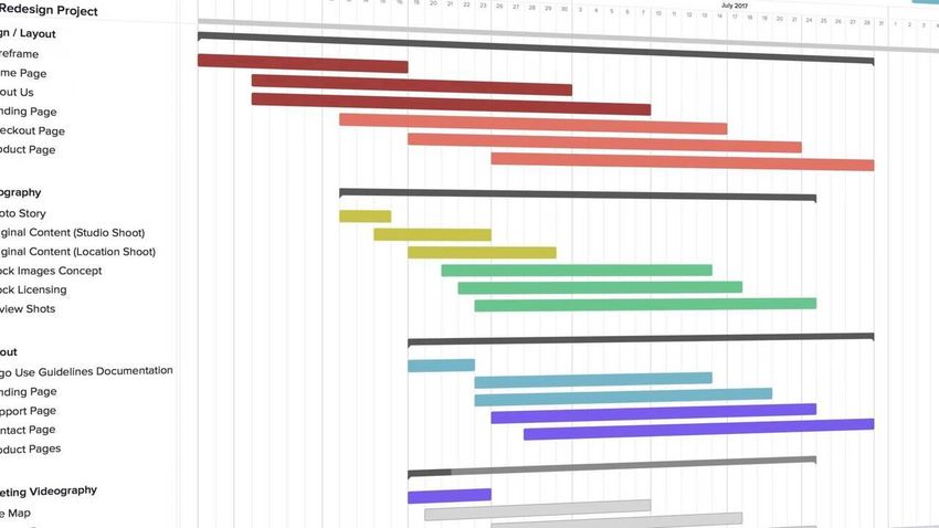
Gantt Chart

              1. Identify required sub-systems for your
                 solution
              2. Organize your work in tasks and
                 subtasks
                  • Sub-systems can be used as a
                      reference to organize tasks
              3. Identify relationships between
                 subsystems and plan the tasks
                 accordingly (in time and contents)
              4. Define appropriate timeslots for each
                 task and subtask
              5. Allocate sufficient human resources to
                 carry out each of your tasks
                  • Define responsibilities
                  • Define required inputs
                  • Define expected outputs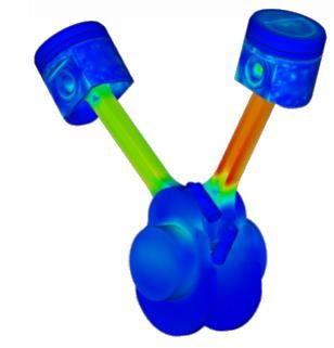
Parts and Assembly Modelling

                       1. Share ideas with your team mates about the
                          software to use and find an agreement
                       2. Define, if needed, an adequate file format for
                          file exchange among team members
                            • If your group uses SolidWorks and Catia,
                                it is easy to share part files between
                                software and also across versions of the
                                same software by means of .3dxml file
                                format to limit feature losses
                       3. Start modelling parts as stated in Gantt
                          Chart (refer to prof. Grafinger’s lecture for
                          modelling guidelines)
                       4. Mate parts and create sub-assemblies
                          according to the Gantt Chart
                       5. Mate sub-assemblies and make a complete
                          3D model of your solution
(Mechanical) Behaviour Assessment

                         1. Identify moving and static parts
                         2. Double check the consistency of
                            mutual relationships
                            between/among parts and
                            subassemblies with the expected
                            analysis you want to run
                         3. Identify working conditions you
                            would like to simulate, for
                            instance:
                             • Constraints
                             • Loads
                             • Movements
                             • Maximum or minimum room
                                  required
                             • …
                         4. Refer to prof. Grafinger’s lecture
                            for simulation guidelines
Consolidation and Documentation
1. Finalize the complete 3D model of
your solution by fixing what was not
satisfactory after the assessment
2. Define a structure for your report
3. Include in your report some crucial
factors to evaluate the goodness of
your solution:
• Manufacturing costs
• Potential sale prices
• Potentially evaluated differences
between Make OR Buy
approaches
4. Attach relevant files to your report
• 3D models
• Bill of Materials (BOM)
• Renders (if any)
• …You can also read