4-wheel stroller with smart emergency brakes system
←
→
Page content transcription
If your browser does not render page correctly, please read the page content below

U KRAINIAN C ATHOLIC U NIVERSITY

                   B ACHELOR T HESIS

4-wheel stroller with smart emergency
            brakes system

 Author:                                             Supervisor:
 Yuliya A NTONYSHYN                             Oleg FARENYUK

      A thesis submitted in fulfillment of the requirements
               for the degree of Bachelor of Science
                             in the

             Department of Computer Sciences
               Faculty of Applied Sciences

                           Lviv 2020
i

Declaration of Authorship
I, Yuliya A NTONYSHYN, declare that this thesis titled, “4-wheel stroller with smart
emergency brakes system” and the work presented in it are my own. I confirm that:

   • This work was done wholly or mainly while in candidature for a research de-
     gree at this University.

   • Where any part of this thesis has previously been submitted for a degree or
     any other qualification at this University or any other institution, this has been
     clearly stated.

   • Where I have consulted the published work of others, this is always clearly
     attributed.

   • Where I have quoted from the work of others, the source is always given. With
     the exception of such quotations, this thesis is entirely my own work.

   • I have acknowledged all main sources of help.

   • Where the thesis is based on work done by myself jointly with others, I have
     made clear exactly what was done by others and what I have contributed my-
     self.

Signed:

Date:
ii

                    UKRAINIAN CATHOLIC UNIVERSITY

                          Faculty of Applied Sciences

                              Bachelor of Science

             4-wheel stroller with smart emergency brakes system
                            by Yuliya A NTONYSHYN

                                Abstract
This work is about inventing smart control system and better mobility system for
baby’s strollers and wheelchairs. The carriages based on a microcontroller helps
reduce the applied force for people driving them. And based on off-road vehicles
canones chassi is a worthy opponent of poor road coverage. Also smart brakes are
great confidence for caretakers in safety on hilly terrain.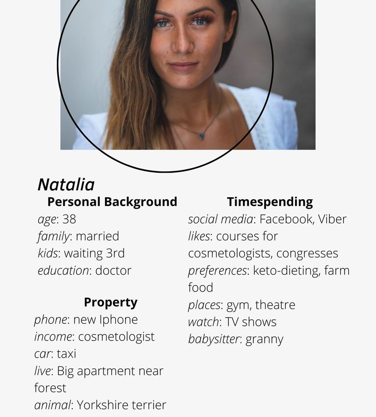
iii

                         Acknowledgements
I want to say thank you to my husband who supported me with coffee and snacks
during my "working hours" and helped me with all the mechanical engineering.
To my son who was the inspiration and the main disorganisation of the process. I
want to say thank you to my parents for all the calming down words. I want to
say thank you to Oleg Farenyuk for answering all of the questions. I want to say
thank you to Kostyantyn from Move.one.design and Serhii from ElectricBikes for all
the clarifications about motor-wheels. I want to say thank you to Markiyan from
SoftServe robotics department. Also I want to say thank you to the university which
gave me the perfect opportunity to start this project and LvBS to their courses that
helped me with business part organisation.. . .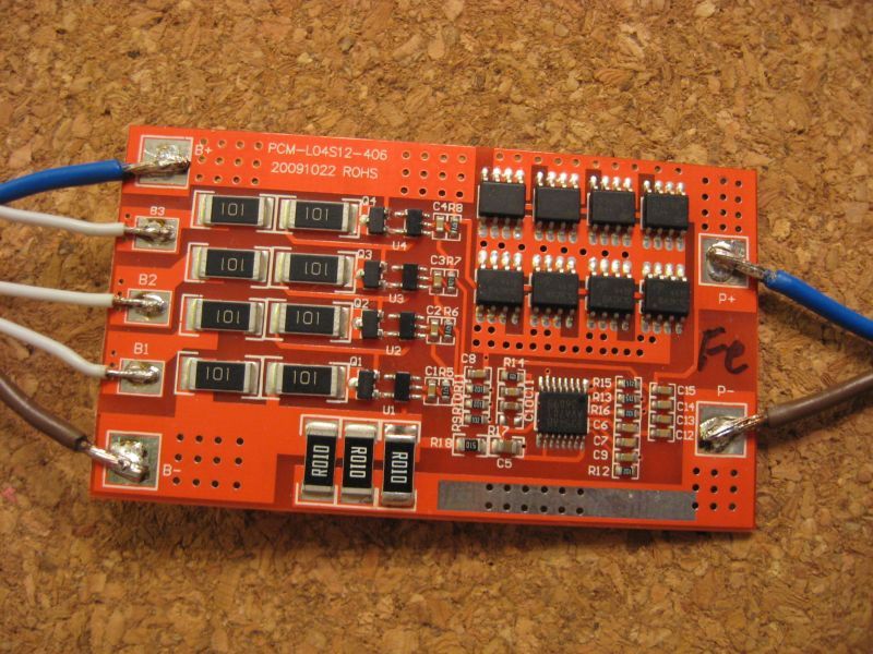
iv

Contents

Declaration of Authorship                                                                                                                                     i

Abstract                                                                                                                                                     ii

Acknowledgements                                                                                                                                             iii

1   Introduction                                                                                                                                              1
    1.1 Relevance of the topic . . . . . . . . . . . . . . . . . . . . . . . . . . . .                                                                        1
    1.2 Goal . . . . . . . . . . . . . . . . . . . . . . . . . . . . . . . . . . . . . . .                                                                    1

2   Business                                                                                                                                                  2
    2.1 Buyer personas .         .   .   .   .   .   .   .   .   .   .   .   .   .   .   .   .   .   .   .   .   .   .   .   .   .   .   .   .   .   .   .    2
    2.2 User stories . . .       .   .   .   .   .   .   .   .   .   .   .   .   .   .   .   .   .   .   .   .   .   .   .   .   .   .   .   .   .   .   .    5
    2.3 Existing solutions       .   .   .   .   .   .   .   .   .   .   .   .   .   .   .   .   .   .   .   .   .   .   .   .   .   .   .   .   .   .   .    5
    2.4 BMC . . . . . . .        .   .   .   .   .   .   .   .   .   .   .   .   .   .   .   .   .   .   .   .   .   .   .   .   .   .   .   .   .   .   .    6
    2.5 SWOT-analysis .          .   .   .   .   .   .   .   .   .   .   .   .   .   .   .   .   .   .   .   .   .   .   .   .   .   .   .   .   .   .   .    7

3   Engineering                                                                                                                                               8
    3.1 Independent suspension . . . . . . . . . . . . . . . . . . . . . . . . . . .                                                                          8

4   Electronics                                                                                                                                              10
    4.1 Battery . . . . .    .   .   .   .   .   .   .   .   .   .   .   .   .   .   .   .   .   .   .   .   .   .   .   .   .   .   .   .   .   .   .   .   10
    4.2 Motor wheel . .      .   .   .   .   .   .   .   .   .   .   .   .   .   .   .   .   .   .   .   .   .   .   .   .   .   .   .   .   .   .   .   .   11
    4.3 PID Controller .     .   .   .   .   .   .   .   .   .   .   .   .   .   .   .   .   .   .   .   .   .   .   .   .   .   .   .   .   .   .   .   .   13
    4.4 PWM . . . . . .      .   .   .   .   .   .   .   .   .   .   .   .   .   .   .   .   .   .   .   .   .   .   .   .   .   .   .   .   .   .   .   .   14
    4.5 Speed control .      .   .   .   .   .   .   .   .   .   .   .   .   .   .   .   .   .   .   .   .   .   .   .   .   .   .   .   .   .   .   .   .   15
    4.6 Distance sensor      .   .   .   .   .   .   .   .   .   .   .   .   .   .   .   .   .   .   .   .   .   .   .   .   .   .   .   .   .   .   .   .   15
    4.7 Tactile sensor .     .   .   .   .   .   .   .   .   .   .   .   .   .   .   .   .   .   .   .   .   .   .   .   .   .   .   .   .   .   .   .   .   17
    4.8 PID Controller .     .   .   .   .   .   .   .   .   .   .   .   .   .   .   .   .   .   .   .   .   .   .   .   .   .   .   .   .   .   .   .   .   19
    4.9 Microcontroller      .   .   .   .   .   .   .   .   .   .   .   .   .   .   .   .   .   .   .   .   .   .   .   .   .   .   .   .   .   .   .   .   21
    4.10 Scheme . . . . .    .   .   .   .   .   .   .   .   .   .   .   .   .   .   .   .   .   .   .   .   .   .   .   .   .   .   .   .   .   .   .   .   22

5   Code                                                                              24
    5.1 Emergency Brakes Algorithm . . . . . . . . . . . . . . . . . . . . . . . . 24
    5.2 Swing Algorithm . . . . . . . . . . . . . . . . . . . . . . . . . . . . . . . 24

6   Conclusion                                                                                                                                               25

Bibliography                                                                                                                                                 26
v

List of Figures

 2.1    User Personas Masha and Borys        .   .   .   .   .   .   .   .   .   .   .   .   .   .   .   .   .   .   .   .   .   .    3
 2.2    User personas Peter and Natalia      .   .   .   .   .   .   .   .   .   .   .   .   .   .   .   .   .   .   .   .   .   .    4
 2.3    BMC analysis . . . . . . . . . . .   .   .   .   .   .   .   .   .   .   .   .   .   .   .   .   .   .   .   .   .   .   .    6
 2.4    SWOT analysis . . . . . . . . . .    .   .   .   .   .   .   .   .   .   .   .   .   .   .   .   .   .   .   .   .   .   .    7

 3.1    Independent suspension (www.drive2.ru) . . . . . . . . . . . . . . . . .                                                      8
 3.2    Paralleled wheels (www.dirtwheelsmag.com) . . . . . . . . . . . . . . .                                                       9

 4.1    Battery Management System (www.electricaltechnology.org)                                             .   .   .   .   .   .   10
 4.2    Electic gear motor construction . . . . . . . . . . . . . . . . .                                    .   .   .   .   .   .   11
 4.3    BLDC motor construction (www.electricaltechnology.org) . .                                           .   .   .   .   .   .   12
 4.4    BLDC working scheme (www.electricaltechnology.org) . . .                                             .   .   .   .   .   .   12
 4.5    Anaheim BLY motor logic (www.anaheimautomation.com) .                                                .   .   .   .   .   .   12
 4.6    ABS working principle(www.toyota.lk) . . . . . . . . . . . .                                         .   .   .   .   .   .   13
 4.7    ABS working scheme (www.agcoauto.com) . . . . . . . . . .                                            .   .   .   .   .   .   13
 4.8    PID controller working scheme (www.researchgate.net) . . .                                           .   .   .   .   .   .   14
 4.9    PWM signal . . . . . . . . . . . . . . . . . . . . . . . . . . . .                                   .   .   .   .   .   .   15
 4.10   Different stroller moves . . . . . . . . . . . . . . . . . . . . .                                   .   .   .   .   .   .   15
 4.11   Infrared sensor working principle . . . . . . . . . . . . . . . .                                    .   .   .   .   .   .   16
 4.12   Infrared sensor working principle . . . . . . . . . . . . . . . .                                    .   .   .   .   .   .   16
 4.13   Laser sensor working principle . . . . . . . . . . . . . . . . .                                     .   .   .   .   .   .   17
 4.14   Distance sensor comparison table . . . . . . . . . . . . . . .                                       .   .   .   .   .   .   17
 4.15   Heart-rate sensor (amazon.com) . . . . . . . . . . . . . . . .                                       .   .   .   .   .   .   18
 4.16   Heart-rate sensor working principle (www.researchgate.net)                                           .   .   .   .   .   .   18
 4.17   Force sensible sensor working principle (www.mouser.com)                                             .   .   .   .   .   .   19
 4.18   Force sensible sensor table (www.mouser.com) . . . . . . . .                                         .   .   .   .   .   .   19
 4.19   ABS working principle (www.toyota.lk) . . . . . . . . . . . .                                        .   .   .   .   .   .   20
 4.20   ABS working scheme (www.agcoauto.com) . . . . . . . . . .                                            .   .   .   .   .   .   20
 4.21   PID controller working scheme (www.researchgate.net) . . .                                           .   .   .   .   .   .   21
 4.23   Stroller working scheme . . . . . . . . . . . . . . . . . . . . .                                    .   .   .   .   .   .   23
vi

List of Abbreviations

     MCU       MicroController Unit
     BMC       Business Model Canvas
     SWOT      Strengths Weaknesses Opportunities Threats
     BLDC      Brushless Direct Current Motor
     BMS       Battery Managenment System
     LiFePO4   Litium Ferro Phosphate
     SOC       State Of Charge
     PID       Proportional-Integral-Derivative
     ABS       Anti-lock Braking System
     PWM       Pulse Width Modulation
     ESC       Electric Speed Controller
     PWM       Pulse Width Modulation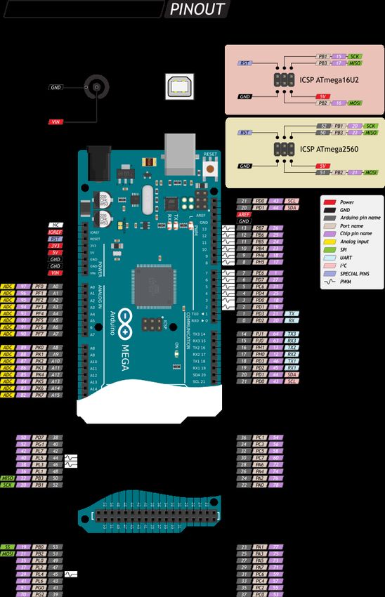
vii

Dedicated to my son. . .
1

1 Introduction

1.1    Relevance of the topic

         Every parent wants the best for his child. Therefore, they start the most
interesting process – choosing baby strollers even before baby’s birth. The hard-
est moment is to decide which company and which stroller model to buy and how
much it is going to cost. Nowadays the market is oversaturated with the number of
different models represented for almost every wallet. The price range is truly wide.
You can buy a stroller from a hundred to almost 7 thousand dollars. But what is the
real difference between those besides brand promotion? Is this just a good market-
ing strategy?
      As I can say from my own experience and market analysis, I did – there is No
big difference, but little things as tactile material, lining material, one or another as-
sembly system, chassis material, wheels size, bag size, weight, cup holder, and so
on. Almost none of these characteristics affects real usage, ride performance, and
wear resistance.
      Most of the young parents and low-mobility people from post-Soviet countries
have one problem in common - sidewalks quality. Pits on roads, cracks on tiles,
crocked pavement, and the worst asphalt – all of that is an integral component of
our everyday life. Unfortunately, barrier-free environment is an unreachable urban-
ist’s dream in Ukraine so far.
     Years ago, babytech was considered a niche market that few investors under-
stood or wanted to get into. Today, anyone considering adding to their family can
find technology for everything from fertility to potty training and beyond. [5] Re-
cently, investors in the United States have invested half a billion dollars in the indus-
try.

1.2    Goal

         The goal is to develop a complex smart stroller system and enter the mar-
ket with this product, which not yet occupied by such devices. Combine modern
technologies and further integrate them into our daily lives. Such as: a function
of assistance on a hill, emergency braking system in case of control loss, automatic
swinging function with a smart proximity sensors system, gadget charging function
from the trolley, soft and long-range independent suspension and a battery charge
indication system.
2

2 Business

         Since I am developing a complete product, not an algorithm or software
separately, I would like to start with the business part.
      Perhaps the most important part of the project is understanding whether your
product is needed on the market or not, what features are going to be in demand
for end-user, and whether it is worth starting this project at all. Because for me any
project including diploma automatically should be something practical for everyday
life and can become profitable in the nearest future.
      Further, in this paper by the word "project", I mean the baby trolley because I am
keen on this topic, and the niche is not competitive yet. When some of the features
are already applied to wheelchairs, however, any systems I have developed can also
be applied to the last ones.
      The best way to start the analysis is to identify the target audience, its needs,
pains, and how to solve them.

2.1    Buyer personas

        To understand my target audience, I will use buyer personas(user personas).
User Personas represent real, living, and breathing people who will engage with
my product, their characteristics.[7] The perfect number of those is 3-5. All of the
personas should be as different as possible but still interested in product to create
clear Target Audience.
    A target audience is the demographic of people most likely to be interested in
your product or service.[6]
Chapter 2. Business 3
F IGURE 2.1: User Personas Masha and BorysChapter 2. Business 4
F IGURE 2.2: User personas Peter and NataliaChapter 2. Business 5
2.2 User stories
User stories are a great method for expressing stakeholder requirements. [13]
• As a user, I want to travel with my child to the mountains and forests and I
want the stroller to have a good suspension that the stroller does not shake on
rocks.
• As a user, I want have free hands while lull my baby, because it takes a long
time for my daughter to fall asleep. so I would like the stroller to do that itself.
• As a user, I want the stroller to speed up so I can put less effort.
• As a user I want to see the battery state of charge to ride safely and know when
to charge it.
• As a user, I want to sit on a bench and read a book, or follow friends on Insta-
gram, so I want the stroller to take care of the child, swing it, but be careful not
to crash into something.
• As a user, I live in an area far from the downtown, and when I walk with a
child I have to walk on pits and destroyed sidewalks, so I want the stroller to
cope well with these inequalities.
• As a user, I have problems with epilepsy, and there have been cases of seizures
while walking with a child. From the new stroller, I want it to stop as soon as
possible if I lose consciousness while walking on the hill.
• As a user I want the stroller to be stylish and innovative and look good with
my Tesla in the garage
• As a user I want to charge my phone and JBL from my stroller, that I can always
be online.
• As a user, I want to have a mechanical handbrake to be independent from
electricity
2.3 Existing solutions
1. Concord Neo. Concord – German carriage manufacturing company founded
in 1978. In 2008 presented their flagship stroller first world known stroller with in-
dependent suspension. After its creation, many versions and improvements have
arrived as the years have progressed, to now become one of the best strollers with
independent suspension on the market.
2. Smartbe Intelligent Stroller - is a revolutionary concept that is self-propelled
or assist-propelled. The stroller stays in front of the user seamlessly synchronized
with their movement with neither assistance nor physical contact. In assist mode it
easily reduces human effort for better control.
3. Skoda vRS Mega Man-Pram – baby stroller made by Skoda company, which
is characterized as big-wheeled-car for babies.Chapter 2. Business 6
2.4 BMC
The Business Model Canvas was proposed by Alexander Osterwalder based
on his earlier book: Business Model Ontology. It outlines nine segments which form
the building blocks for the business model in a nice one-page canvas. That‘s the
most common instrument of presenting business strategy.[1]
Each block presents a certain business model element explained below.
F IGURE 2.3: BMC analysis
• 1. Customer segment
For whom I am creating value and which segment is most important?
• 2. Value proposition
How will I turn an unaware visitor into an interested customer? What can I of-
fer a customer that he really needs? A clear and compelling one-liner message
I want to send across.
• 3. Channels
How will I reach my target consumers? Direct marketing, social media, ads,
partnerships — these are the effective ways to reach them.
• 4. Customer relationships
This block is about communication with the end-user. How am I going to
review if everything is ok while using or choosing the product?
• 5. Revenue streams
What money sources will grow money? How will I generate income? A pric-
ing model of my product.
• 6. Key Resources
Any resources that are going to be needed while production, advertising and
selling the product and also documenting production.Chapter 2. Business 7
• 7. Key Activities
All the activities my value proposition requires. All the processes.
• 8. Key partners
These are partners without whom the business itself cannot exist. The ones
giving key resources.
• 9. Cost structure
What are the fixed and variable costs to launch my product?
2.5 SWOT-analysis
SWOT analysis or SWOT matrix is strategic planning instrument used to help
identify strengths, weaknesses, opportunities, and threats related to business com-
petition.
F IGURE 2.4: SWOT analysis8
3 Engineering
As there is the need to add comfort, off-road capabilities and maximum quality
and durability to the product, especially on bad roads, I decided to create a spacious
aluminum frame. The cradle and controls will be attached to the top and four wheels
on independent suspension, two of which are motor wheels on the bottom side.
Based on the experience of SUVs, ATVs, UTVs, and off-road trucks, it was de-
cided to use a two-lever independent suspension with shock absorber struts.
3.1 Independent suspension
The independent two-lever suspension is two V-shaped levers located one above
another. The tops of the levers are hinged to the ends of the hub and the forked ends
are attached to the frame.
F IGURE 3.1: Independent suspension (www.drive2.ru)
In my prototype the spring is used for the tone of the carriage and the shock-
absorber is used for attenuation of oscillations. The best solution is to combine the
spring and the shock absorber into one rack, it will give compactness and maintain-
ability. The biggest advantage of this type of suspension is the large damping capac-
ity required for comfortable crossing of high curbs, road pits and uneven seams, as
well as the fact that the suspension does not change the inclination of the wheels. As
it demonstrated on the image below. The upper and lower levers are always parallel
to each other. That is, even with intense oscillation of the suspension, the wheels
will always be perpendicular to the road, which adds safety and comfort.Chapter 3. Engineering 9
F IGURE 3.2: Paralleled wheels (www.dirtwheelsmag.com)
In the automotive industry there is only one significant disadvantage of the two-
lever suspension - such a system takes up a lot of hood space, which complicates the
placement of the engine, but while designing a stroller it is not a problem, because
the lower part of the frame is open and the cradle and all other units are high enough.
So there is enough space for the suspension. In the central part of the frame, to
which the levers are attached, battery is located to move the center of mass as low as
possible.
Currently there is no stroller model on the market with an independent two-
lever suspension on all four wheels. In most upgraded strollers the suspension is
represented by interlocking wheels on the beam, which are shock-absorbed by weak
plastic springs. This dependent suspension has insufficient comfort properties, be-
cause if the left wheel falls into the pit, the angle of the right wheel will be directed
to the left, and will pull the entire frame of the stroller to the left side. Because of
this, the cart will shake violently on pits and uneven surfaces.10
4 Electronics
4.1 Battery
There are several types of chemical batteries on the market nowadays. Prior
to the invention of lithium-ion batteries(in 1980s), the undisputed market leaders
were lead-acid batteries. These are really good for electrical transport where the
weight is not a key characteristics. Lithium-ion (Li-ion) is currently the most popular
due to its low weight, low cost and durability. Another great type of batteries is
LiFePO4. They have better temperature range, more charge-discharge cycles and
bigger lifetime, but there are some cons comparing to Li-ions, as bigger weight and
higher price.Also, Li-ion batteries have the highest efficiency coefficient - 95percent
,what is 15percent higher than lead-acid batteries level. That’s one more thing why I
would use Li-ion.A lot of different manufacturers are presented on the market with
their products, but as experience shows Samsung company is the race dealer. The
declared capacity of their batteries corresponds to the actual.
Every Li-ion battery has its Battery Management System(BMS), which does cur-
rent protection (protects from short circuit and higher current level) , voltage protec-
tion (protects from overcharging and overdischarging), temperature protection and
balancing (evenly distributes the charge between all cells of the battery, due to which
the battery life is maximized.)
F IGURE 4.1: Battery Management System
(www.electricaltechnology.org)
Structurally on the board are placed:
• protective chip
• analog wiring (for detecting current / battery balancing)
• power transistors (to disconnect the load)Chapter 4. Electronics 11
Using Battery Management System capabilities we can easily track battery charge
level (SOC- state of charge) and theoretically lifetime cycles. The most accurate re-
sults for the SOC estimation can be obtained by OCV (Open Circuit Voltage) mea-
surement after the load is removed.[8]
Lithium batteries are charged in 2 stages: CC (constant current) and CV (constant
voltage). The charger gradually raises the voltage so that the charged cell takes
back current (the usual recommended value is 1 battery capacity). When the voltage
reaches 4 V, charging proceeds to the second stage and maintains a voltage of 4.2 V
on the battery.
4.2 Motor wheel
An electric vehicle is propelled by electric motors of either AC or DC, which
is internal combustion engine alternative due to pollution concern, cost, and avail-
ability of the oil. AC and DC motors have the same function - converting electrical
energy into mechanical energy, while they are powered, constructed and controlled
differently. [10] The biggest difference is that AC motors are powered by alternat-
ing current when DC - from direct current such us batteries, other DC supplies or
an AC-to-DC power converter. The speed of a D.C. motor is controlled by varying
the armature winding’s current while the speed of an A.C. motor is controlled by
varying the frequency, which is commonly done with an adjustable frequency drive
control. [4]
F IGURE 4.2: Electic gear motor construction
DC motors are mainly used in production since batteries are used as the main
power source. BLDC motors are often used in techniques due to high efficiency, high
power density, large starting torque, noiseless operation, low weight and smaller in
size. Modern vehicles are powered by hub type BLDC motors, motors in-build in
the wheel, to avoid complex powertrain mechanism.
Unlike conventional brushed type DC motor, wherein the brushes make the me-
chanical contact with commutator on the rotor so as to form an electric path between
a DC electric source and rotor armature windings, BLDC motor employs electrical
commutation with permanent magnet rotor and a stator with a sequence of coils. InChapter 4. Electronics 12
this motor, permanent magnet (or field poles) rotates and current carrying conduc-
tors are fixed.
F IGURE 4.3: BLDC motor construction
(www.electricaltechnology.org)
To rotate the motor continuously the electronic controller scheme turn on ap-
propriate motor winding by turning transistor or other switches. The figure below
shows a simple scheme of a BLDC moto: MOSFET bridge (inverter bridge), an elec-
tronic controller, a Hall effect sensor, and a BLDC motor. In addition to switching to
the rated engine speed, an additional electronic circuit can change the engine speed.
Typically, these speed control units are PID controllers.
F IGURE 4.4: BLDC working scheme (www.electricaltechnology.org)
In my project for MVP I use regular 3phase Anaheim BLDC motor BLY171-174S
with a motor driver for it.
F IGURE 4.5: Anaheim BLY motor logic
(www.anaheimautomation.com)Chapter 4. Electronics 13
4.3 PID Controller
The main goal while creating smart brakes system and electronic handbrakes is
to make a system which will work similarly to ABS Anti-lock braking system. It pre-
vents the wheels from locking up and helps them maintain grip with the road below.
The main purpose of the ABS is to ensure optimal braking efficiency while maintain-
ing the stability and control ability of the car. ABS generally offers improved vehicle
control and decreases stopping distances on dry and some slippery surfaces, when
on snowy surfaces improve control level and increase stopping distance. Why is this
important? Without ABS a car on the road with it’s big weight and high speed can
cause skidding while braking. In terms of baby trolley locking up the wheels can
cause flipping a stroller due to high center-of-mass location.
In such difficult practical problems as designing an ABS great result shows us-
ing fuzzy logic controls.[9] A fuzzy control system, which is the system that fuzzy
controls use, analyzes analog input values in terms of logical variables that take on
continuous values between 0 and 1, in contrast to classical or digital logic, which
operates on discrete values of either 1 or 0 (true or false, respectively).[11]
F IGURE 4.6: ABS working principle(www.toyota.lk)
F IGURE 4.7: ABS working scheme (www.agcoauto.com)
In some cases for an car ABS fuzzy or regular PID controllers are used.[3] What
is PID (proportional–integral–derivative) controller by itself? It is a loop mechanism
which is used in automatic control systems to generate a control signal in order to
obtain the necessary accuracy and quality of the transition process. To simplify the
explanation I would say that if you have something like a car you might want to
have a cruise control in it which maintains a constant speed of the car, automati-
cally adding gas when the speed decreases and decreasing when it increases, forChapter 4. Electronics 14
example, on the slopes, without the participation of the driver. This is what PID
controller does it takes some variable for example speed and compares it with some
ideal constant in 3 phases:
• If IT(speed) is higher/lower than a Constant (Proportional phase),
• and the deviation between the speed and a ideal constant becomes bigger (In-
tegral phase)
• and the speed of the deviation increase increases (Derivative phase)
• Then command - decrease/increase the speed.
One more version to explain PID controller working process is to make an ana-
logue with time where Proportional component is Present (if the speed is bigger
now?), Integral component is Past (if the speed is bigger for some time?), Derivative
is Future(what the speed are going to be next moment?) and summarizing all of the
components answers the best decision can be made.
F IGURE 4.8: PID controller working scheme (www.researchgate.net)
When you try to press the brake-pedal while ABS is working you would feel the
vibrating pulsation this mean that controller is giving a brake signal using PWM.[12]
Unfortunately, it is hardly to use PID in emergency braking system, due to small
speed differences. PID controllers are used in wider speed ranges (automotive and
rocketry), but with really small values it will take too long to respond. The alterna-
tive way is to use PI controller, without a derivative component. Or create totally
independent software algorithm for smart braking system. MVP testing is needed
to decide which variant is better, second or third.
4.4 PWM
One very simple and easy way to control the speed of DC motors is to use PWM.
Pulse-width modulation - is a method that helps reduce electric power by chopping
signals into discrete parts. It gives the analog results with digital means. Also in
small motors the power loss in the switching transistor is small because the transistor
can be just ON or OFF. It results in more stable speed.Chapter 4. Electronics 15
F IGURE 4.9: PWM signal
4.5 Speed control
For MVP I use regular joystick with the analog signal in two axis which gives
two analog signals (0-1023, 0-1023). Since there is no full backward stroller moving
provided (except braking when motors do pulsating backward move using PWM).
Vertical axe gives easier or harder forward move and horizontal axe gives the small
or big difference in wheel speeds in accordance to joystick output. This how we can
make easier turns in addition to forward move.
( A ) Forward move ( B ) Turn left ( C ) Turn right
F IGURE 4.10: Different stroller moves
4.6 Distance sensor
Distance sensor functions by outputting a signal (depending on technology:
ultrasonic waves, IR, LED, etc.) and measuring the change when the signal returns.
There are two ways which change to measure:
• Time taken to send and receive signal
• The intensity of received signalChapter 4. Electronics 16
By simple formulas both of ways can be used to calculate the distance between a
sensor and a target.
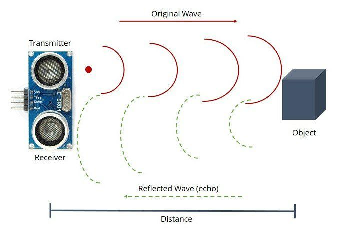
Ultrasonic sensor
The first technology commonly used in markets is using ultrasonic waves. Also
known as the Sonar sensor, it detects the distance to objects by emitting high-frequency
ultrasonic waves (from the transmitter(trig pin)) and calculating time till the wave
is received back (to the echo pin), the time is used to calculate the distance.
F IGURE 4.11: Infrared sensor working principle
IR distance sensor
The second on the list is infrared distance sensor which works through the prin-
ciple of triangulation. IR LED emitter lens emits a light beam, it reflects from an
object and a position-sensible photodetector (PSD) receive the beam. Then the an-
gle between emitted and reflected light beam is measured and distance is calculated
using a formula
F IGURE 4.12: Infrared sensor working principle
Laser distance sensor. LiDAR Sensor
LiDAR is short for Light Detection And Ranging. It measures the distance through
light waves from a laser instead of radio or sound waves. The transmitter emits laser
light, target object reflects the light back and the distance is easily calculated using
the constant speed of light in air and time between sending and receiving the signal.Chapter 4. Electronics 17
F IGURE 4.13: Laser sensor working principle
LED Time-Of-Flight Distance sensor. This sensor is the smallest flight ranging
and gesture detection sensor.This types of sensors are very accurate and really good
in 3D imaging. Works similarly to Lidar sensors.
Summarizing all of the info I made comparison table. And decided that I will in-
clude 3/4 distance sensors types in my MVP to test what type would be the best on
practice. The only one I definitely will not use is LiDAR sensor due to high price.
F IGURE 4.14: Distance sensor comparison table
4.7 Tactile sensor
To check whether a person holding a stroller or not multiple sensors and check-
ing algorithms were analyzed. A tactile sensor is a device that measures the received
information in response to the physical interaction with the environment. [2]
The first one was a heart rate sensor, which basically is a powerful LED, a special
brightness sensor, an active filter and a useful signal amplifier on the operational
amplifier. The working principle of the sensor based on the change of light reflection
by the skin and measuring how it scatters off blood vessels.Chapter 4. Electronics 18
F IGURE 4.15: Heart-rate sensor (amazon.com)
• Pros - it is cheap, easy to use
• Cons - it is really small so hands should be straight in one position, it is an
optical sensor so it is not desirable to press it firmly against the skin and you
need to avoid exposure to external light sources.
F IGURE 4.16: Heart-rate sensor working principle
(www.researchgate.net)
Second type is FSR sensors. FSRs are sensors that allow you to detect physical
pressure, squeezing and weight. The round part is the sensitive bit. Basically these
are resistors that change their resistance value (in Ohms) depending on the force on
the surface. When there is no pressure, the sensor looks like an infinite resistor, as
the pressure increases, the resistance goes down. What is especially important that
the low force measurements it quickly goes from infinite to 100(KOhms).Chapter 4. Electronics 19
F IGURE 4.17: Force sensible sensor working principle
(www.mouser.com)
Here is a table of dependencies between force and resistance value, where R is
pulldown resistor. They are easy to use, low cost but rarely accurate. Thankfully for
this project I do not need weight accuracy so this sensor fits perfectly on the stroller’s
handle.
F IGURE 4.18: Force sensible sensor table (www.mouser.com)
4.8 PID Controller
The main goal while creating smart brakes system and electronic handbrakes is
to make a system which will work similarly to ABS Anti-lock braking system. It pre-
vents the wheels from locking up and helps them maintain grip with the road below.
The main purpose of the ABS is to ensure optimal braking efficiency while maintain-
ing the stability and control ability of the car. ABS generally offers improved vehicle
control and decreases stopping distances on dry and some slippery surfaces, when
on snowy surfaces improve control level and increase stopping distance. Why is this
important? Without ABS a car on the road with it’s big weight and high speed can
cause skidding while braking. In terms of baby trolley locking up the wheels can
cause flipping a stroller due to high center-of-mass location.
In such difficult practical problems as designing an ABS great result shows using
fuzzy logic controls. A fuzzy control system, which is the system that fuzzy controls
use, analyzes analog input values in terms of logical variables that take on continu-
ous values between 0 and 1, in contrast to classical or digital logic, which operates
on discrete values of either 1 or 0 (true or false, respectively).[11]Chapter 4. Electronics 20
F IGURE 4.19: ABS working principle (www.toyota.lk)
F IGURE 4.20: ABS working scheme (www.agcoauto.com)
In some cases for an car ABS fuzzy PID controllers are used.[3] What is PID
(proportional–integral–derivative) controller by itself? It is a loop mechanism which
is used in automatic control systems to generate a control signal in order to obtain the
necessary accuracy and quality of the transition process. To simplify the explanation
I would say that if you have something like a car you might want to have a cruise
control in it which maintains a constant speed of the car, automatically adding gas
when the speed decreases and decreasing when it increases, for example, on the
slopes, without the participation of the driver. This is what PID controller does it
takes some variable for example speed and compares it with some ideal constant in
3 phases:
• If IT(speed) is higher/lower than a Constant (Proportional phase),
• and the deviation between the speed and a ideal constant becomes bigger (In-
tegral phase)
• and the speed of the deviation increase increases ( Derivaive phase)
• Then command - decrease/increase the speed.
One more version to explain PID controller working process isChapter 4. Electronics 21
F IGURE 4.21: PID controller working scheme (www.researchgate.net)
When you try to press the brake-pedal while ABS is working you would feel the
vibrating pulsation this mean that controller is giving a brake signal using PWM.
4.9 Microcontroller
There is huge amount of absolutely different microcontrollers. Single-chip mi-
crocontrollers (MK) are intended for use in industrial and household automation
systems. They are large integrated circuits that include all the devices necessary
for implementing a digital control system with a minimum configuration: proces-
sor, memory of commands, memory of data, clock generator, programmable de-
vices for communication with the external environment (interrupt controller, timer
counters, various input / output ports), sometimes analog-to-digital and digital-to-
analog converters, etc. In order not to describe all the differences between them here
is a list of characteristics according to which I choose the one.
• easy to program
• low price
• small in sizes
• PWM pins
• sufficient speed
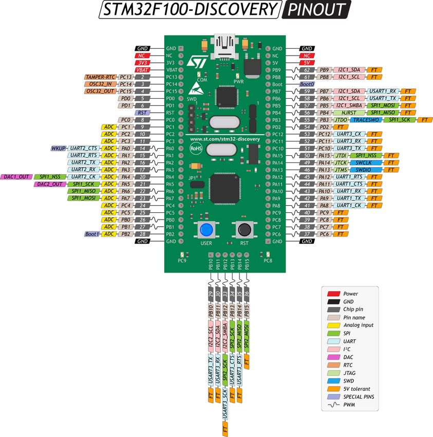
Since big amount of modern microcontrollers can do that I choose two that I used
to work with. An Arduino Mega for MVP and the STM32 Discovery for production
version of a stroller. Both of the microcontrollers presented have 16 PWM pins, 2 I2C
interface pinsChapter 4. Electronics 22
( A ) Arduino MEGA Pinout(wiki.amperka.ru)
( B ) STM32 Pinout(wiki.amperka.ru)
4.10 Scheme
Summarizing all of the component analysis here is an electronic part scheme.Chapter 4. Electronics 23
F IGURE 4.23: Stroller working scheme24
5 Code
5.1 Emergency Brakes Algorithm
The emergency brake algorithm uses the information from tactile sensor (force-
sensible sensor), ultrasonic sensor, infrared sensor, hall sensors from which we know
the answers for a number of questions.
• If the hands are on the handle or not?
• If the stroller is moving?
• How fast the stroller moves?
• How fast the stroller is moving?
• If there is some barrier on the way?
• How far the barrier is?
So the logic is - IF (hands are not on the handle AND acceleration is not equal to
zero (stroller is moving) for more then 2 seconds) OR the distance to the barrier is
less then 30cm THEN motor should stop.
Using PWM method controller send to the motor driver a command to stop
the motor (pulsating signals(-1) to spin backward) using a dependency function be-
tween the speed and the acceleration to choose the right frequency for PWM signal.
5.2 Swing Algorithm
According to my observations and tests with different people, the average value
of the distance traveled by the stroller when rocking a child is 97cm. By simple
calculations we get the circle length from a wheel radius. Now dividing mean value
from my tests by the circle we can get number of turns the wheel need to do.
After that controller send to the motor driver a command to do straight amount
of turns forward (drive forward), then slowly stop, then do straight amount of turns
backward (drive backward) then slowly stop and so on.
Speed is also controlled (stabilized) by PWM on the stated frequency.
The stopping function is realized in the same way as in emergency braking.25
6 Conclusion
The topic for this work was chosen by me not by chance. A few years ago, my
youngest brother was born, four more siblings before him, and recently my own son
appeared in this world, and when I just started to walk outside with my brother’s
stroller, I noticed a lot of problems with the stroller market. In a world where the
best is done for children, the highest quality, where the compositions of dry mixes
for feeding is better than the menu in the most expensive restaurant, where safety
regulations for child car seats are stricter than the rules of making spacecraft, no one
pays attention to the stroller market. And I’m sure that if this problem has affected
me, it has affected thousands of young parents who cannot buy a stroller that meets
the pace of modern innovation just because it not exist. Why, when we can ride
hoverboards, we can’t easily control a stroller with the most expensive we have?
Why, launching rockets to another planet, people still didn‘t made a comfortable
suspension on a baby, damn, stroller? I am sure that many people ask themselves
these questions, but few have the ability and opportunity to change something. So I
decided to try, to make a smart and modern device to make the time of walking with
your child more enjoyable, comfortable and safer.26
Bibliography
[1] Ana Paula B. Business model elements for product-service sys-tem. URL: https://
www.researchgate.net/publication/226896588_Business_Model_Elements_
for_Product-Service_System.
[2] Oussama Khatib Bruno Siciliano. Springer Handbook of Robotics. URL: https :
//books.google.com.ua/books?id=Xpgi5gSuBxsC.
[3] Kirpichnikov A.P. Burakov M.V. NECHETKIJ REGULYATOR PID-TIPA DLYA
NELINEJNOGO OB.
[4] Robert S. Carrow. Electrician’s Technical Reference: Variable Frequency Drives. URL:
https : / / books . google . com . ua / books ? id = gMIZHvBrw4MC & pg = PA45 # v =
onepage&q&f=false.
[5] Christine Hall. Babytech Boom: Millennials, Startups Pave Way For Growth. URL:
https://news.crunchbase.com/news/babytech-boom-millennials-startups-
pave-way-for-growth/.
[6] Laura Lake. What Is Your ’Target Audience’ in Marketing? URL: https://www.
thebalancesmb.com/what-is-a-target-audience-2295567.
[7] Abbie Griffin Michael G. Luchs Scott Swan. Design Thinking: New Product De-
velopment Essentials from the PDMA. URL: https://books.google.com.ua/
books?id=PutRCgAAQBAJ&pg=PA28&dq=User+buyer+personas+Personas&hl=
ru&sa=X&ved=0ahUKEwiG49fakqnpAhWPvosKHT_RCZwQ6AEIPjAC#v=onepage&q=
User%20buyer%20personas%20Personas&f=false.
[8] Fecir Duran3 Mustafa Turgut1 Raif Bayir2. CAN Communication Based Mod-
ular Type Battery Management System for Electric Vehicles. URL: http : / / www .
eejournal.ktu.lt/index.php/elt/article/view/20975/9441.
[9] A.S.KONOVALOV M.V. Burakov. NECHETKOE UPRAVLENIE AVTOMOBIL’NOJ
ANTIBLOKIROVOCHNOJ SISTEMOJ. URL: https://cyberleninka.ru/article/
n/nechetkoe- upravlenie- avtomobilnoy- antiblokirovochnoy- sistemoy/
viewer.
[10] Saeed B. Niku. Introduction to Robotics: Analysis, Control, Applications. URL: https:
/ / books . google . com . ua / books ? id = 2V4aGvlGt7IC & pg = RA1 - PA280 # v =
onepage&q&f=false.
[11] Witold Pedrycz. Fuzzy control and fuzzy systems. URL: https://books.google.
com . ua / books / about / Fuzzy _ control _ and _ fuzzy _ systems . html ? id =
uupSAAAAMAAJ&redir_esc=y.
[12] Steve Senty. Motor Control Fundamentals. URL: https://books.google.com.
ua/books?id=s4csCQAAQBAJ.
[13] Thomas and Angela Hathaway. Writing Effective User Stories: As a User, I Can
Express a Business Need in ... URL: https://books.google.com.ua/books?id=
jO29DwAAQBAJ.You can also read