ES-405 PARTICULATE PROFILER OPERATION MANUAL - Met One
←
→
Page content transcription
If your browser does not render page correctly, please read the page content below
ES-405
                                PARTICULATE PROFILER
                                 OPERATION MANUAL
                                                  REVISION C

                 Met One Instruments, Inc.
                 1600 NW Washington Blvd.
                 Grants Pass, Oregon 97526
                 Telephone 541-471-7111
                 Facsimile 541-471-7116

ES-405 Particulate Profiler Operation Manual - © Copyright 2020 Met One Instruments, Inc. All rights reserved
worldwide. No part of this publication may be reproduced, transmitted, transcribed, stored in a retrieval system, or
translated into any other language in any form without the written permission of Met One Instruments, Inc.

                                             ES-405-9800 Manual Rev C                                      Page 1
ES-405-9800 Manual Rev C Page 2
Table of Contents
1   INTRODUCTION ..................................................................................................................5
    1.1    About This Manual................................................................................................................................. 5
    1.2    Technical Service and Warranty ......................................................................................................... 5
    1.3    About the ES-405 .................................................................................................................................. 6
    1.4    Laser Radiation Safety and Conformity.............................................................................................. 6
    1.5    ES-405 Specifications ........................................................................................................................... 7

2   ES-405 SETUP and STARTUP ........................................................................................8
    2.1    Standard and Optional Accessories ................................................................................................... 8
    2.2    Mounting Options................................................................................................................................... 8
    2.3    Setting Up the ES-405 .......................................................................................................................... 9
    2.4    Electrical Connections ........................................................................................................................ 12
    2.5    Power-Up and Starting Operation ..................................................................................................... 12
    2.6    Default Setup ........................................................................................................................................ 13

3   SITE SELECTION and REMOTE POWER OPTIONS ................................................14
    3.1    Site Selection Requirements .............................................................................................................. 14
    3.2    Fall Hazard and Security Cautions ................................................................................................... 15
    3.3    Confined Sampling Locations ............................................................................................................ 15

4   ES-405 USER INTERFACE and MENU SYSTEM ......................................................16
    4.1    The User Interface - Keypad and Display Functions ...................................................................... 16
    4.2    Using the Main Sampling Screen ...................................................................................................... 17
    4.3    Using the Main ES-405 Menu System and Clearing Memory ...................................................... 18

5   ES-405 MEASUREMENT METHOD ..............................................................................19
    5.1    Sheath Air ............................................................................................................................................. 19
    5.2    Detection ............................................................................................................................................... 19
    5.3    Sizing and Counting ............................................................................................................................ 19
    5.4    Calibration ............................................................................................................................................. 19
    5.5    K-Factor ................................................................................................................................................ 19
    5.6    Sample RH Control for Light Scatter Mass ...................................................................................... 20

6   SETUP MENU DESCRIPTIONS .....................................................................................21
    6.1    SAMPLE Setup .................................................................................................................................... 21
    6.2    CLOCK Setup....................................................................................................................................... 22
    6.3    SERIAL PORT ..................................................................................................................................... 22
    6.4    MEMORY .............................................................................................................................................. 22
    6.5    ALARM OUTPUT ................................................................................................................................. 23

                                                                 ES-405-9800 Manual Rev C                                                                            Page 3
7 CALIBRATE MENU – FIELD CALIBRATIONS ...........................................................24
7.1 CALIBRATE Menu............................................................................................................................... 24
7.1.1 CALIBRATE Flow Screen ........................................................................................................... 24
7.1.2 CALIBRATE FP Screen ............................................................................................................... 25
7.1.3 K-FACTOR Screen ....................................................................................................................... 25
8 MAINTENANCE and TROUBLESHOOTING ...............................................................26
8.1 Basic Problem and Cause/Solution Table ....................................................................................... 26
8.2 Suggested Periodic Maintenance Intervals ..................................................................................... 27
8.3 AQ Flow Calibration ............................................................................................................................ 27
8.4 Filter Change ........................................................................................................................................ 27
8.5 TSP Inlet Cleaning............................................................................................................................... 27
8.6 Factory Service Interval ...................................................................................................................... 28
9 DATA RETRIEVAL and COMMUNICATIONS .............................................................29
9.1 Serial Port Connections to a Computer ............................................................................................ 29
9.2 Modem Options for Remote Data Retrieval ..................................................................................... 29
9.3 Comet™ Data Retrieval Software ..................................................................................................... 29
9.4 Downloading Data Using a Terminal Emulator ............................................................................... 30
9.5 Data Retrieval Commands Through the Serial Port ....................................................................... 30
9.5.1 User Communication ................................................................................................................... 30
9.5.2 Computer Communication .......................................................................................................... 31
9.5.3 Computer Command Format ...................................................................................................... 31
9.5.4 Checksum Computation .............................................................................................................. 31
9.5.5 Serial Command List .................................................................................................................... 31
9.6.3 SK Command ................................................................................................................................ 33
10 PARTS and ACCESSORIES...........................................................................................34
10.1 Consumables, Replacement Parts, and Accessories .................................................................... 34
10.2 Combination Sensor Options ............................................................................................................. 35
10.2.1 EX2-034 ......................................................................................................................................... 35
10.2.2 EX2-AIO ......................................................................................................................................... 35
10.2.3 597A ............................................................................................................................................... 36
10.3 CCS Modem ......................................................................................................................................... 36
ES-405-9800 Manual Rev C Page 41 INTRODUCTION
1.1 About This Manual
This document is organized with the most important information grouped together for easy
reference by the user. All ES-405 owners and operators should read and understand the sections
on installation, setup, and field calibrations. Other sections that provide in-depth information on
subjects such as theory, diagnostics, accessories, and alternate settings provide valuable
information which should be consulted as needed. An electronic version of this manual is also
available.
1.2 Technical Service and Warranty
This manual is structured by customer feedback to provide the required information for setup,
operation, testing, maintaining, and troubleshooting your ES-405 unit. Should you still require
support after consulting your printed documentation, we encourage you to contact one of our
expert Technical Service representatives during normal business hours of 7:00 a.m. to 4:00 p.m.
Pacific Time, Monday through Friday. In addition, technical information and service bulletins are
often posted on our website. Please contact us and obtain a Return Authorization (RA) number
before sending any equipment back to the factory. This allows us to track and schedule service
work and to expedite customer service.
Phone: (541) 471-7111 Fax: (541) 471-7116
E-Mail: service@metone.com Web: www.metone.com
Address: Technical Services Department
Met One Instruments, Inc.
1600 NW Washington Blvd.
Grants Pass, OR 97526
ES-405-9800 Manual Rev C Page 51.3 About the ES-405
The Met One Instruments, Inc. model ES-405 Particulate Profiler is a near reference air quality
sensor which automatically measures and records real-time airborne PM1.0, PM2.5, PM4.0, and
PM10 particulate concentration levels using the principle of right angle laser light scatter. Detailed
descriptions of the ES-405 measurement modes can be found in Section 5.
Laser Light Scatter System
Sample air is drawn into the ES-405 detector chamber and subjected to an intense laser beam
located at right angles to the flow. Particles pass through the laser beam and scatter light that is
collected onto a photodiode detector. The output of the detector is analyzed to determine the
number and size of the particles and mathematically processed to provide an indicative particulate
mass measurement.
1.4 Laser Radiation Safety and Conformity
The ES-405, when properly installed and operated, is considered a Class I laser product.
Class I products are not considered to be hazardous.
This system contains a diode laser operating at 100 mW power and 785 nm wavelength. This is
not visible to the naked eye and can cause damage to the eye if directly exposed. A protective
optical housing fully encapsulates the laser beam and optics system within the ES-405. Do not
attempt to disassemble the optical module. Failure to comply with this instruction could cause
accidental exposure to laser radiation. The manufacturer certifies that this product operates in
compliance with following standards and regulations:
FDA / CDRH This product is tested and complies with 21 CFR, Subchapter J, of the
health and Safety Act of 1968.
US 21 CFR 1040.10.
Always power down the system whenever service or repair work is being performed inside the
instrument enclosure. Only trained technicians should attempt to repair the ES-405. Routine
maintenance does not require removing the instrument from its weatherproof enclosure.
ES-405-9800 Manual Rev C Page 61.5 ES-405 Specifications
PARAMETER SPECIFICATION
Measurement Principles: Right angle light scatter detection, using a laser diode as light source.
Number of Mass Channels: 4 (PM1.0, PM2.5, PM4.0, PM10)
Sample Air Flow Rate: 1.0 LPM
Sheath Air Flow Rate: 1.0 LPM
Flow Control: Active Volumetric Flow Control
Data Storage Resolution: 0.1 µg/m3
Data Storage Intervals: User-Selectable 1, 5, 10, 15, 30, or 60 minutes.
Laser Type: Diode Laser, 100 mW, 785 nm.
Pump Type: 10,000 hour brushless diaphragm pump.
Power Supply: Universal 100-240 VAC input, 50/60Hz.
1.0 amp @ 12 VDC (12 Watts) average continuous draw with inlet heater running.
Power Consumption: 0.63 amps (8 Watts) running with inlet heater off.
Operating Temperature: 0 to +50°C
Storage Temperature: -20º to +60º C
Ambient Humidity Range 0 to 95% RH, non-condensing.
Humidity Control Automatic 10 Watt inlet heater module controlled to sample RH, with set point.
User Interface: Menu-driven interface with 4x20 character OLED display and dynamic keypad.
RS-232, full duplex serial port for PC or datalogger communications.
RS-485, half duplex for modem communications.
Serial Interface:
RS-485, half duplex for sensor communications.
USB port for PC communications.
Baud = 115200, 8 data bits, no parity, and 1 stop bit. (factory Default)
Serial Settings:
115200, 57600, 38400, 19200, 9600, 4800, 2400 (selectable).
Alarm Contact Closure: Normally closed contact closure relay output. Contact rating 1.0A @ 30V DC max.
Compatible Software: Comet™, terminal programs such as HyperTerminal®
Factory Service Interval: 24 Months typical, under continuous use in normal ambient air.
Mounting Options: Pole or wall mount bracket standard. Optional EX-905 tripod recommended.
Unit Weight 11.2 lbs
Unit Dimensions Height: 24" Width: 12" Depth: 6.75"
Specifications may be subject to change without notice.
ES-405-9800 Manual Rev C Page 72 ES-405 SETUP and STARTUP
The ES-405 is designed for rapid deployment and easy setup by a single person in less than 15
minutes in most applications. This section describes the basic assembly, setup, and start-up of the
instrument.
2.1 Standard and Optional Accessories
When unpacking a new ES-405, verify that the contents are undamaged. If the shipping cartons
are damaged, notify the carrier immediately. Verify that the included accessories are correct and
complete. If anything is missing, contact the technical service department at service@metone.com
or (541) 471-7111. See the Accessories section at the back of this manual for more details. The
normal configuration of the ES-405 is supplied with the following standard accessories:
Weatherproof TSP inlet with debris screen.
Instruction manual.
External power supply and cable.
USB Cable.
Grounding Cable.
Pole/wall mounting bracket.
The following optional accessories may or may not also be included, depending on the order:
Serial communications cable.
Aluminum tripod.
External digital MET sensors.
External alarm cable.
External DC power cable for batteries or solar systems.
Modem kits for phone line, cell, radio, or satellite telemetry.
Solar power kits (usually drop-shipped from the solar manufacturer). A DC/DC controller is highly
recommended to regulate incoming voltage to 12V.
2.2 Mounting Options
Custom Pole or Wall Mounting:
The ES-405 can be mounted to a pole, mast, or wall using the included mounting bracket. The
bracket must be screwed or bolted to the pole or wall with appropriate hardware. The enclosed
bolts may not be appropriate for the desired mounting. The slot on the back of the ES-405 slips
over the tab on the mounting bracket. The tab on the bottom of the ES-405 should also be bolted
to the mounting surface to ensure that the unit cannot be knocked off its mounting.
Typical Mounting Bracket Pole Installation
Note: If mounting the unit to a wall, take care to ensure that there is adequate clear space around
the inlet to allow unrestricted airflow into the instrument. Wall mounting is often not considered
ES-405-9800 Manual Rev C Page 8ideal and not recommended due to the airflow and particulate obstruction of the wall itself. Mount
the instrument with no large obstructions nearby whenever possible.
Tripod Mounting:
The Met One EX-905 aluminum tripod is the recommended mounting for the ES-405 for most
outdoor applications. It is not included as a standard accessory in order to save expense for users
who may not require it. Deploy the tripod as follows:
1. Remove the three stainless steel detent pins from the tripod base by pulling the rings.
Unfold the three tripod legs and reinsert the three pins so that each pin secures a leg in
the open position. Make sure the erected tripod is rigid and stable.
Detent Pins
2. Lift the ES-405 assembly and slide the slot on the back of the ES-405 over the tab on
the top of the tripod. Insert the supplied ¼-20 bolt through the tab on the bottom of the
ES-405 and through the hole in the body of the tripod. Secure it with the supplied
washers and nut. This prevents the ES-405 from falling or shifting on the tripod.
3. Site the tripod on a surface that is as level as possible. The tripod feet may be secured
to the ground or mounting surface with bolts, screws, or tent pegs if necessary. Secure
the tripod in windy conditions!
2.3 Setting Up the ES-405
Set up the rest of the ES-405 hardware items and accessories as described below:
1. Install TSP inlet: The included weatherproof TSP inlet is simply installed directly onto the
top of the ES-405 inlet tube to keep water, insects, and debris out of the instrument.
Lubricate the o-rings if necessary. Never operate the ES-405 outdoors without the TSP
inlet in place, as the resulting water/debris damage is not covered under warranty.
2. Optional MET sensor: If an optional MET sensor is supplied, it may come with a cross-
arm tube which mounts to the stud on the top of the EX-905 tripod with supplied fittings.
Install the MET sensor on the end of the cross-arm. The sensor should be as far from the
ES-405 unit as possible without affecting the tripod balance. If a wind vane is employed, it
must be able to rotate fully without hitting anything. Plug the MET sensor into the
corresponding connector on the bottom of the ES-405. Consult the separate manual that
comes with the MET sensor for alignment details.
3. AC Power Supply: If the ES-405 is to be operated on AC line voltage, bolt the power
supply to one of the legs of the tripod with U-bolts. Plug the power supply output cable into
ES-405-9800 Manual Rev C Page 9the DC power input on the bottom of the ES-405. When the power supply is plugged into
AC power, the ES-405 will turn on automatically.
ES-405-9800 Manual Rev C Page 109441
TSP Cap
(included)
Heated Inlet
Assembly 12”
(included)
11.5”
ES-405 12”
Total Height:
( 6.75” deep ) 72”
905 Tripod
(optional)
48”
AC to 12 VDC
Power Supply
Standard ES-405 Configuration
Not to scale. Some items simplified for clarity. 41” triangular
tripod footprint
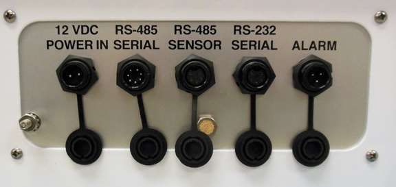
ES-405-9800 Manual Rev C Page 112.4 Electrical Connections
The ES-405 has five weatherproof connectors on the bottom of the enclosure. These
connectors provide the connections for the power supply, external sensors, communications, and
alarm options. Each connector has a different pin configuration to prevent plugging cables into the
wrong
connector. The ES-405 will turn on automatically whenever a 12V power source is connected
to the power input.
The ES-405 chassis ground lug should be connected to an earth ground with the supplied
grounding cable whenever possible, to reduce potential EMI/RFI electrical noise in the unit.
The RS-485 SERIAL connection is for an optional CCS Modem or optional RS-485 half-duplex
cable. The RS-485 SENSOR connection is for an optional MET Sensor. The RS-232 SERIAL
connection is for RS-232 communications. The ALARM connection is for the optional alarm
output.
Chassis Ground Lug
2.5 Power-Up and Starting Operation
As soon as power is applied to the ES-405, the unit will boot up and display ES-405 and company
website for a few seconds.
The ES-405 will then default to the OPERATE screen as shown below and begin sampling.
Pressing the Enter key on the keypad will bring up the START or STOP screen depending on
whether or not the unit is currently sampling.
ES-405-9800 Manual Rev C Page 12Pressing the ▼ down arrow displays the readings that do not fit on the screen. The MET data will
only display if optional digital sensors are connected
2018-08-03 11:34:10
SAMPLING...
PM2.5 31.2 ug/m3
PM10 137.8 ug/m3
PM1 26.6 ug/m3
PM 4 51. 9 ug/m3
FLOW 1.00 lpm
FT 25.4 C
FP 735.1 mmHg
AT 36.9 C
RH 35.1 %
BP 745.1 mmHg
WS 8.4 m/s
WD 175 deg
2.6 Default Setup
The ES-405 is factory configured to measure continuously with one-minute sample. The following
table lists some of the factory default configurations which may need to be changed for your
application. See Section 6 for details about the settings.
Parameter Setting
Sampling Rate 1 minute
Time Pacific Time
PM1 K-Factor 1.0
PM2.5 K-Factor 1.0
PM4 K-Factor 1.0
PM10 K-Factor 1.0
Baud Rate 115200
ES-405-9800 Manual Rev C Page 133 SITE SELECTION and REMOTE POWER OPTIONS
Use the following criteria when deciding on a sampling location for the ES-405. Always consider
the safety and security of the unit, as well as the suitability of the sampling environment.
3.1 Site Selection Requirements
Selection of a proper site for the ES-405 is critical for accurate measurements.
The following is a summary of general ambient particulate monitoring site requirements that will be
appropriate for use with the ES-405 in many cases. Some of these criteria may not be appropriate
in some applications, due to the versatile nature of the ES-405:
Inlet Height:
The inlet should be located in the “breathing zone”, between 2 and 15 meters above ground
level. When installed on the standard tripod, the ES-405 inlet is positioned two meters
above the ground or other mounting surface.
If the ES-405 is to be collocated with other particulate instruments, such as FRM filter-type
samplers or BAM units, then the air inlet must be the same height as the inlet of the other
samplers, within one meter vertically. Within one foot is preferred.
If the ES-405 inlet is the highest point on a building, then lightning rods must be installed to
prevent destruction of the unit during electrical storms.
Inlet Radius Clearance:
The ES-405 inlet should have a one meter radius free of any objects that may influence
airflow characteristics, including the inlet of another instrument.
If an ES-405 is to be collocated at a station along with BAM or FRM samplers, the inlets of
each sampler must be no less than one meter apart from each other, and no more than
four meters apart. Two meter inlet spacing is recommended where possible.
If installed near a Hi-Volume sampler, then the distance between the inlet of the ES-405
and the Hi-Vol must be no less than two meters.
The ES-405 inlet should be located away from obstructions such as short walls, fences,
and penthouses, so that the inlet is unobstructed for two meters in all directions whenever
possible. In some ES-405 applications, this may not be entirely possible.
If located beside a major obstruction (such as a building) then the distance between the
ES-405 and the building should be equal to twice the height of the building.
The inlet should be at least 20 meters from the drip line of any overhanging trees.
There should be at least a 270 degree arc of unrestricted airflow around the inlet. The
predominant direction of concentration movement should be included in the arc.
Artificial Particulate Sources:
To avoid possible errors in the concentration measurements, the inlet must be located as far as
possible from any artificial sources of particulate, such as blowers, vents, or air conditioners on a
rooftop. Especially if any of these types of devices blow air across the inlet of the ES-405. Even
sources of filtered air must not blow across the inlet.
ES-405-9800 Manual Rev C Page 14Spacing from Roadways:
The ES-405 should usually not be located directly next to a major highway or arterial roadway, as
vehicle exhaust will dominate the concentration measurement. This effect can be difficult to
predict accurately as shifting winds may direct the plume toward or away from the inlet. An
obvious exception would intentional roadside particulate studies.
Roads with a daily traffic volume of less than 3,000 vehicles are generally not considered
major sources of pollutants, and in this case the ES-405 should be located at least five
meters from the nearest traffic lane.
The ES-405 should be located at least 25 meters from any elevated roadway greater than
five meters high.
The unit should be located as far as possible from unpaved roadways, as these also cause
artificial measurements from fugitive dust.
The unit should not be installed in unpaved areas unless year-round vegetative ground
cover is present, to avoid the effects of re-entrained fugitive dust.
3.2 Fall Hazard and Security Cautions
If the ES-405 is to be installed more than three meters above ground level, then the tripod legs
must be bolted down to prevent the unit from falling to the ground. An accidental fall may cause
major optical system damage requiring that the unit be returned to the factory for repairs. In
addition, dropping the ES-405 from any height will cause a potential safety hazard for those
below, and may damage the unit beyond repair.
The ES-405 tripod should be secured to the mounting surface in windy conditions to prevent the
unit from falling over, even at ground level. This is especially important in winds over 30 mph. If
bolt-down is not possible, then the tripod legs may be weighted down with sand bags or cinder
blocks to secure the unit. Wind or fall damage is not covered under warranty.
The ES-405 should be secured from theft or vandalism to the extent possible. A limited-access
rooftop or a fenced lot are often good places to deploy the unit. Solar panels and batteries are
highly susceptible to theft and should be secured.
3.3 Confined Sampling Locations
Because of the portable and versatile nature of the unit, the ES-405 is sometimes deployed in
confined or non-ambient locations to monitor localized particulate sources, such as tunnels,
mines, quarries, shopping malls, train stations, etc. Each of these applications is unique and
presents various challenges. We recommend that you contact a Met One Service representative
to determine the suitability of the unit if you plan a custom deployment like this. In any case, the
safety of those around the unit is paramount, and the protection of the unit from damage is very
important.
ES-405-9800 Manual Rev C Page 154 ES-405 USER INTERFACE and MENU SYSTEM
This section describes the ES-405 user interface system, and describes the functions of the main
menu options, including how to view data and errors.
4.1 The User Interface - Keypad and Display Functions
The ES-405 user interface consists of a 4x20 character organic light-emitting diode display
(OLED) and a dynamic keypad. The two white keys under the display are called “soft keys”. These
are dynamic keys which change in response to a menu option displayed directly above the key on
the bottom row of the display. The function of these keys depends on which menu is shown on the
display and are often used for functions such as “SAVE” and “EXIT”.
The four, red arrow (cursor) keys are used to scroll up, down, left, and right, to navigate in the
menu system, and to select items or change fields on the screen. The arrow keys are also often
used to change parameters or increment/decrement values in the menu system. The right arrow
key can be used to wake up the display if it has turned off to save power.
The MENU key is used to enter the main menu or to select an item in a list. The ESC key is used
to escape or exit out of a menu.
ES-405 Keypad and Display
ES-405-9800 Manual Rev C Page 164.2 Using the Main Sampling Screen
The ES-405 display shows the Operate screen when the unit is in normal operation. The active
display area shows the current date and time and most recent measurement concentration. Not
all the parameters monitored by the ES-405 can fit on the screen, press the down ▼ arrow to view
the remaining parameters. The date and time will remain at the top of the display at all times.
Main Sampling Screen
Below is a table which describes the parameters visible in the main sampling display as shown
above. These are all the logged parameters in the ES-405. The active display shows the 1-second
real-time value for each parameter, while the stored data shows the average value over the user-
selected logging interval. AT, RH, BP, WS and WD are only visible if an external digital MET
sensor is attached.
Parameter Description
PM2.5 Real-time particulate concentration, in micrograms per cubic meter.
PM10 Real-time particulate concentration, in micrograms per cubic meter.
PM1 Real-time particulate concentration, in micrograms per cubic meter.
PM4 Real-time particulate concentration, in micrograms per cubic meter.
FLOW Real-time sample flow rate, in actual liters per minute.
FT Internal temperature in degrees C.
FP Internal barometric pressure in mmHg.
AT External ambient temperature in degrees C (if equipped).
RH External ambient relative humidity (if equipped).
BP External ambient barometric pressure in mmHg (if equipped).
WS Wind speed in meters per second (if equipped).
WD Wind direction in degrees (if equipped).
The Main ES-405 screen
ES-405-9800 Manual Rev C Page 17Pressing the Enter key while in the Operate screen will either bring up the Start or Stop screen
depending on whether the instrument is currently sampling or not.
START MEASUREMENT STOP MEASUREMENT
CANCEL START CANCEL STOP
4.3 Using the Main ES-405 Menu System and Clearing Memory
MENU SCREEN: The first line of the Menu screen is Start or Stop depending on whether the
instrument is currently sampling or not.
STOP SAMPLE
SETUP MENU
CALIBRATE MENU
ALARMS
ABOUT
The main ES-405 menu system can be entered at almost any time by pressing the MENU key.
Use the ▲▼ arrow keys to select the desired menu option, then press the MENU key to enter the
selected sub-menu. The functions in the SETUP and CALIBRATE menus are described in Section
6 and 7.
SETUP: This is the setup menu for the ES-405. All the setup parameters in this menu are
described in Section 6.
CALIBRATE: This is the field calibration menu for the ES-405. All the calibrations and tests in
this menu are described in Section 7.
ABOUT: This menu option displays the ES-405 model number, firmware version and revision,
and serial number as shown in the example below. Press the MENU/SELECT key to return to the
main menu.
ES-405
83904 R1.2.0
X15465
WWW.METONE.COM
ES-405-9800 Manual Rev C Page 185 ES-405 MEASUREMENT METHOD
The Met One Instruments, Inc model ES-405 is a type of air quality sensor which automatically
measures and records real-time airborne PM10, PM4, PM2.5, and PM1 particulate concentration
levels using the principle of right-angle laser light scatter. This section describes the
measurement systems.
5.1 Sheath Air
The Particle Profiler uses a sheath air system. When a particle counter is to be used to sample
aerosols containing high concentrations of particles, the sensor should incorporate sheath air to
prevent particles from contaminating the internal optics of the sensor. The particle laden sample
air is enclosed in a sheath of clean filtered air that prevents particles from escaping. Sample air is
drawn into the ES-405 by an internal pump. Flow rate is controlled with a flow sensor to maintain
constant 1 LPM flow on the inlet nozzle. Additional air is added around the sample flow to contain
the particles.
5.2 Detection
The ES-405 is always ready to detect particles. Sample air is drawn into the detector chamber
and subjected to an intense laser beam located at right angles to the flow. The laser beam has
been shaped to produce a flat very thin beam, producing a small sample area. Light travels
through the sample stream and terminates in the light trap. Particles pass through the laser beam
and scatter light. The amount of light scattered is proportional to the size of the particle. A portion
of this light scatters toward the elliptical mirror. This light is then directed to the detector. The
output of the detector is then analyzed to determine the number of particles and the size of the
particles. Detected particles are multiplied by a fixed density to provide an indicative particulate
mass measurement.
5.3 Sizing and Counting
The amount of scattered light is converted to a voltage pulse and based on the amplitude of the
pulse signal it will pass through one or more of the size discriminators and into the associated
counter(s).
5.4 Calibration
Calibration is performed using ideal (PSL) spheres, which provide a powerful tool for assessing
the sensitivity, accuracy, resolution and false count level. The particle detector is compared to a
reference mono-dispersed (single size) suspension of polystyrene latex (PSL) spheres in clean
filtered air for both calibration and certification of performance specifications. This calibration
technique serves two purposes:
1. Provides a standard traceable reference.
2. Provides a measure of how well the unit maintains its calibration (reproducibility).
5.5 K-Factor
The AQ Mass Profiler’s PSL sphere calibration provides an extremely consistent calibration but
does not generally match the characteristics of all ambient particulate. A K-Factor (multiplier)
must be established for good accuracy and correlation to collocated instruments.
ES-405-9800 Manual Rev C Page 19It is best to compare the ES-405 to regulatory monitors distinguished as Federal Reference
Monitors (FRM) or Federal Equivalent Monitors (FEM). Contact your local air quality authorities
for information on locations and how to access the data. Some sites may have hourly data, while
others may have 24-hour data.
Calculate the K-Factor for each particulate size fraction as the reference concentration divided by
the ES-405 light scatter concentration over the same time period. For example, if the reference
total concentration was 51 μg/m3 and the ES-405 total concentration was 38 μg/m3, then the K-
Factor would be 51 divided by 38 or 1.342. If only one size fraction K-Factor will be calculated for
the unit it is advisable to use this number for all four PM sizes.
The K-Factor is only valid at the same site and for the same particulate type. If the local particulate
source changes, the K-Factor may no longer be valid. The accuracy of the mass output can be
affected by variations in size, color, shape, and index of refraction of the sampled particles. The K
Factor for each PM mass fraction can be set in the calibrate menu.
5.6 Sample RH Control for Light Scatter Mass
The relative humidity (RH) of the sample air has an influence upon the measurement of particulate
mass by optical units. At RH values greater than about 50% this effect begins to increase due to
particle aggregation and particle size increases as water is absorbed. The ES-405 mitigates this
through a heated inlet tube that uses an internal sample RH sensor. The RH of the incoming air is
measured, and the inlet heater is turned on whenever the user-set setpoint is exceeded (typically
40% RH).
ES-405-9800 Manual Rev C Page 206 SETUP MENU DESCRIPTIONS
The ES-405 has a system of setup menus which contain all of the settings and parameters
needed to perform the measurement and operation of the unit. Many of these settings are set at
factory default values which are correct for most applications but may be altered by the operator to
suit the specific needs of your monitoring program. This section describes the SETUP menu in
detail and should be reviewed to ensure desired operation. Once set, most of the values in the
SETUP menus will not need to be changed by the site operator. The settings will not be lost if the
unit is unplugged or powered down.
The SETUP menu can be accessed through the main ES-405 menu. Use the arrow keys to select
SETUP option in the main menu, then press the MENU key to enter the menu.
Use the ▲▼ keys to select the desired sub-menu and press the ENTER key again to enter. The
top SETUP menu is shown below:
SAMPLE
CLOCK
SERIAL PORT
MEMORY
ALARM OUTPUT
6.1 SAMPLE Setup
Set the Sample Rate and Location ID
SAMPLE RATE: 5 MIN
LOCATION: 001
The Sample Rate choices are a pick list with the following choices.
SAMPLE RATE: 1 MIN
5 MIN
10 MIN
15 MIN
30 MIN
1 HR
ES-405-9800 Manual Rev C Page 216.2 CLOCK Setup
Press the ENTER key. Scroll left and right to access each field to edit. Use the Up/Down arrows
to change each field as it flashes. Press ENTER key when complete, then press the soft key
under SET to finish.
SET CLOCK
2018-08-03 11:45:31
SET
6.3 SERIAL PORT
Set the baud rate for RS-232 and USB serial communication.
Baud rate choices are a pick list with the following choices:
BAUD: 2400
4800
9600
19200
38400
57600
115200
6.4 MEMORY
Allow to clear the files.
FILE: ALL LOGS
CLEAR
Choices
FILE: DATA LOG
ALARM LOG
ALL LOGS
ES-405-9800 Manual Rev C Page 226.5 ALARM OUTPUT
This screen is used to establish the rules for activating the alarm contact closure relay output of
the ES-405. This contact closure connection is located on the bottom of the enclosure and
requires an optional cable with the contact wires routed out. The contacts are normally
open/normally closed and will close/open when the event is triggered. This can be used to signal
an external warning light, logic controller, or logger input to take some action. The optional
external alarm cable (MOI part number 83569) relay wiring function is as follow:
Red=Normally Open, Black=Normally Closed, Green=Common.
Select the OUTPUT SOURCE, OUTPUT TIMING, or PM LIMITS screen as shown below.
OUTPUT SOURCE
OUTPUT TIMING
PM LIMITS
The alarm OUTPUT SOURCE can be set to ALARM EVENT or PM LIMIT. Setting ALARM
EVENT means that any instrument error or alarm will activate the output. The PM LIMIT setting is
real-time concentration threshold that will trigger the alarm and can be set from 0.1 to 999.9 μg/m3
for each PM size.
Press the ENTER key. Use the Up/Down arrows to select the source. Press ENTER key.
SOURCE: PM LIMIT
The OUTPUT TIMING screen is used to set how long the alarm signal is ACTIVE when triggered
(1 to 60 seconds) and how much delay time must pass before the alarm can be reactivated again
(1 to 60 minutes).
ACTIVE: 10 SEC
DELAY: 01 MIN
The PM LIMITS screen is used to set the individual PM trigger Levels for each of PM1, PM2.5,
PM4 and PM10. Setting the trigger level to 0 will disable triggering of the output for the specified
PM Level.
Press ENTER to begin and end editing the PM limit for each mass size.
PM1: 000.0 ug/m3
PM2.5: 000.0 ug/m3
PM4: 000.0 ug/m3
PM10: 000.0 ug/m3
ES-405-9800 Manual Rev C Page 237 CALIBRATE MENU – FIELD CALIBRATIONS
The ES-405 has a system of calibration menus which allow the operator to audit or calibrate the
airflow control system parameters for optimal performance. These parameters are often audited
monthly and calibrated quarterly during continuous operation. The exact frequency may vary
depending on the harshness of the local conditions and the data validation requirements
established by the sampling program administrator and your resulting standard operating
procedures (SOP).
The CALIBRATE menu is located in the main ES-405 menu. Use the arrow keys to select
CALIBRATE option in the main menu, then press the ENTER key to enter the menu. Use the ▲▼
keys to select the desired sub-menu and press the ENTER key again to enter. The top
CALIBRATE menu is shown below
7.1 CALIBRATE Menu
CALIBRATE FLOW
CALIBRATE FP
K -FACTORS
7.1.1 CALIBRATE Flow Screen
SET POINT: 1.0 lpm
FLOW: 1.00 lpm
STANDARD: 1.00
DEFAULT CALIBRATE
The SET POINT parameter is the target flow rate that the ES-405 will attempt to maintain.
The FLOW parameter is the current reading from the ES-405 flow sensor, in actual volumetric
liters per minute. The ES-405 should automatically regulate to the setpoint (1.0 LPM) when the
flow calibration screen is entered. This may take a moment.
The STANDARD parameter is where you can enter the correct value from your traceable flow
meter, using the arrow keys. The flow reading that you enter must be in actual conditions.
The FLOW value should change to match the STANDARD value when you press the CALIBRATE
soft key.
The DEFAULT soft key can be pressed to clear out all previous field calibrations and restore the
factory calibration for the sensor. Use this if difficulty is encountered during the calibration. Press
ESC to escape without changes.
Note: To audit the ES-405 flow rate without changing the calibration, simply compare the FLOW
value to your traceable standard and record the results. If the CALIBRATE soft key is not pressed,
then no flow calibrations are affected.
ES-405-9800 Manual Rev C Page 247.1.2 CALIBRATE FP Screen
FP: 731.3 mmHg
STANDARD: 731.3 mmHg
DEFAULT CALIBRATE
The FP parameter is the current reading from the ES-405 pressure sensor. The STANDARD
parameter is where you can enter the correct value from your traceable pressure standard, using
the arrow keys. You will need to convert units if your standard outputs pressure in other units. The
FP value should change to match the STANDARD value when you press the CALIBRATE soft
key. The DEFAULT soft key can be pressed to clear out all previous field calibrations and restore
the factory calibration for the sensor. Use this if difficulty is encountered during the calibration.
Press ESC to escape without changes.
7.1.3 K-FACTOR Screen
Press Enter to begin and end editing the K-Factor value for each mass size.
PM1 K: 1.000
PM2.5 K: 1.000
PM4 K: 1.000
PM10 K: 1.000
ES-405-9800 Manual Rev C Page 258 MAINTENANCE and TROUBLESHOOTING
This section provides information about routine maintenance of the ES-405, and for performing
more detailed diagnostic tests if a problem is encountered. The ES-405 generates error messages
on the display or in the data log if a failure or other problem is detected. Many times, there is a
simple solution. Persistent errors often signify a failure which will require investigation.
WARNING: The ES-405 Particulate Profiler can only be serviced or calibrated by factory-
authorized personnel. Unauthorized maintenance on the Particle Profiler may result in exposure to
laser radiation that can cause blindness and void warranty.
The ES-405 is an extremely component-dense assembly! Only skilled and trained electro-
mechanical technicians should attempt any disassembly or repairs inside the ES-405. Routine
maintenance procedures do not involve removing the ES-405 assembly from the enclosure.
Calibrating particle sensors like the one in the ES-405 Particle Profiler requires specialized
equipment and a skilled technician. Met One Instruments maintains a calibration facility for
calibrating particle counters according to industry-accepted methods using NIST traceable
standards. The ES-405 Particle Profiler should be calibrated on a 24 month basis.
8.1 Basic Problem and Cause/Solution Table
The following table contains information on some of the more common ES-405 problems which
may be encountered, and some steps to identify and remedy the problems. Met One welcomes
customer suggestions for new items to include in this section of future manual revisions. If the
solution cannot be found in the following table, then contact one of our expert service technicians
for help in resolving your problem.
Problem: The ES-405 won’t start a measurement cycle.
Cause/Solution: You must press the START SAMPLE key to start continuous operation.
The unit will not start a cycle if the input DC voltage is below the restart threshold,
such as 10 volts DC.
Problem: Flow failures or low flow.
Cause/Solution: Check the filter. This must be replaced periodically.
Try to DEFAULT the flow sensor calibration. If corrupted flow cal parameters are
entered into the flow calibration, it may appear that the flow system is not working.
Verify the internal AT and BP sensors function. They appear as FT and FP on the
main screen when their output is enabled. Failed sensors can affect the flow.
The sample pump itself will eventually wear out and need to be replaced. It should
last at least a year under normal conditions. Check the other possibilities first.
Problem: Optical system alarms and failures
Cause/Solution: The ES-405 must be periodically returned to the factory for optical system cleaning.
The period will depend on your particulate levels.
Check the filter and replace as needed.
The laser diode has a finite lifetime which will be reduced at high temperatures. It
may eventually fail and need to be replaced at the factory.
ES-405-9800 Manual Rev C Page 26Problem: The ES-405 data does not match BAM or FRM data at the same site
Cause/Solution: A K-Factor (multiplier) must be established for good accuracy and correlation to
collocated instruments. The K-Factor will sometimes be very significant, such as a
multiplier of 3 or 5. See Section 5.5.
The K-Factor is only valid at the same site and for the same particulate type. If the
local particulate source changes, the K-Factor may no longer be valid.
The ES-405 TSP inlet is designed for low winds only. High winds may cause a cut-
point in the TSP inlet itself.
Clean the TSP inlet monthly.
Check the sample RH data and filter RH sensor operation. High sample RH will
cause ES-405 over-reading. The sensor itself can occasionally fail.
Check the ES-405 for flow calibration problems.
Check the alarm log for optical system alarms.
8.2 Suggested Periodic Maintenance Intervals
The following table shows the Met One recommended period for routine maintenance items.
Some of these items will need to be performed more, or less, often depending on the exact
characteristics of your location. The program administrator should review these items and
establish SOPs appropriate for your application.
Maintenance Item Suggested Period
AQ Flow Audit/Calibration Monthly
Calibrate Sensor 24 Months
TSP Cleaning Monthly
Replace Filter Yearly
8.3 AQ Flow Calibration
Connect a flow meter to the inlet nozzle of the ES-405 Particle Profiler and allow the flow to
stabilize. If it is not 1.00 LPM ± 0.02LPM, then it needs to be calibrated. Refer to Section 7.1.1.
8.4 Filter Change
The filter cartridge is located in the front panel of the instrument. It can be removed by unscrewing
the black Delrin filter holder. The expected lifetime of the filter is one year, but in heavy particulate
areas they may need to be replaced more often. The replacement filter p/n is 580358.
8.5 TSP Inlet Cleaning
The TSP inlet must be cleaned periodically. The time interval between cleanings varies depending
on the local particulate levels. The TSP inlet should be disassembled and cleaned at least every
three months during continuous use.
The TSP inlet can be disassembled for cleaning by removing the three screws in the cap. Soap
and water often work best for cleaning the TSP inlet and debris screen. Do not over-tighten the
screws during reassembly or the plastic threads will strip out.
ES-405-9800 Manual Rev C Page 278.6 Factory Service Interval
The ES-405 needs to be periodically returned to the factory for service and recalibration. The
recommended period is 24 months during continuous use. However, some users establish their
own interval depending on the harshness of the sampling conditions, particulate levels, and data
scrutiny. High concentration operation will often require more frequent factory service.
Factory service primarily consists of optical system cleaning, laser/detector checks, and
recalibration. As-found calibration checks can also be requested. Contact the Met One technical
service department to schedule ES-405 service. A Return Authorization (RA) number must be
obtained before the unit is returned.
ES-405-9800 Manual Rev C Page 289 DATA RETRIEVAL and COMMUNICATIONS
This section describes the methods used to retrieve data files from the ES-405. The unit has a
single serial data output which can be routed through the RS-232 data port or the USB serial port,
and may be used with a local computer, laptop, or digital datalogger. An RS485 output is available
for connection to the CCS modem to allow remote data viewing and collection. Access to the data
through the serial port is easy using the Comet software or simple terminal or escape commands.
9.1 Serial Port Connections to a Computer
The ES-405 can be directly connected through the supplied USB cable to most standard desktop
computers and laptops. The USB port is located behind the front door, in the bottom right of the
unit.
The ES-405 can be directly connected through the purchased serial cable to desktop computers
that have a 9-pin (DB-9) RS-232 serial port connector.
The ES-405 default settings are 115200 Baud, 8 data bits, no parity, one stop bit, no flow control.
The baud rate may be changed to a slower rate. The other communications settings are fixed.
9.2 Modem Options for Remote Data Retrieval
Met One Instruments CCS cloud display and storage cell modem is recommended for remote
access to the ES-405. Contact Met One for details.
9.3 Comet™ Data Retrieval Software
The ES-405 is compatible with the Comet™ program, which is a simple Windows-based
communications terminal program developed by Met One Instruments. This is the recommended
method for all ES-405 data retrieval, since Comet allows the user to easily download the data
logs, error logs, and settings files from the ES-405 without the user having to know any of the
underlying communications protocols. A comprehensive pdf user’s manual for the program is also
available from the Met One Instruments website. Install the program onto the computer that will be
used for data retrieval and review the manual for complete data examples.
Note: If the Comet software is being used for data retrieval, none of the terminal mode commands
shown in the following sections of this manual will be needed.
Comet is a communications terminal program which can retrieve data from the ES-405 using
either a direct local connection or a remote connection via various modem types or even an IP
address.
Warning: A Silicon Labs CP210x Driver for the USB connection must be installed before
connecting to the USB Type B port.
Driver download weblink: https://www.silabs.com/products/development-tools/software/usb-to-
uart-bridge-vcp-drivers
Note: Before using the USB Type B port, ensure an existing RS-232 connection is disconnected.
The Comet program is available from the Met One Instruments website:
https://metone.com/products/comet/
Install the program on the computer, then run it from the Programs directory. Create a new station
for the ES-405 and then use it to retrieve the data from the ES-405 monitor.
ES-405-9800 Manual Rev C Page 29The Comet program has a “Terminal” button which provides access to the ES-405 just as when
using any other terminal program.
9.4 Downloading Data Using a Terminal Emulator
ES-405 data can also be easily downloaded through the serial port using a terminal emulator
program, like PuTTY. Connect the serial port of the ES-405 to your computer or laptop serial port
using the supplied serial cable.
Importing the raw text file into a spreadsheet:
The data saved in a text file from a terminal download can be viewed by simply opening the text
file. However, the data is often hard to view in the raw text format due to the comma-separated
layout of the data fields. The easiest way to analyze the data is to open it as a .csv file into a
spreadsheet program such as Excel®:
1. Open the spreadsheet program.
2. Select to open the downloaded file. The program should prompt you how to delimit the
fields. Select comma.
3. The text file can be opened directly with Excel or similar software. Each data parameter
should appear in its own spreadsheet column, with the correct data header at the top of
each column. You can then save the file as a spreadsheet file if desired.
9.5 Data Retrieval Commands Through the Serial Port
When a serial connection between the computer terminal program and the ES-405 has been
established, you will have access to the ES-405 data files by sending the following commands
through the serial port with keyboard strokes or ASCII characters.
There are two modes of communication:
1. User communication – This is a user interactive mode using simple letter commands for
ease of use.
2. Computer communication – This mode is used for computer-to-device communication. It
has a level of data integrity.
9.5.1 User Communication
In the user communication mode (terminal mode), press the Enter key, , three times to enter
the mode. In this mode simple character commands can be issued with no character
required.
An asterisk character appears during wake-up and after a command has completed. The asterisk
indicates that the instrument is ready for a new command.
Commands are echoed back from the instrument in this mode. Commands are terminated by the
Enter key .
A help menu can be viewed by sending H, h, or ?; giving all the commands available to the user.
Pressing , X or Q will exit user mode
ES-405-9800 Manual Rev C Page 30Note: After a few minutes, the ES-405 will stop waiting for a command and you will have to send
another series of three carriage returns to reestablish the command prompt connection.
9.5.2 Computer Communication
In the computer communication mode, the command format has an optional level of data integrity
– checksum. This is enabled whenever an character is sent to the instrument. Character
echo is suppressed in this mode.
9.5.3 Computer Command Format
The computer command has the following format:
Cmd p1 p2*cs
Computer commands are prefaced with an (0x1B) character followed directly by a
command, Cmd, which is variable in length depending on the command. After the command
characters there can be zero or more parameter fields, p1 p2. Each parameter field is delimited by
one or more Space characters (0x20).
A computer command example follows:
rv
ES-405, 83904, R1.2.0.0a
9.5.4 Checksum Computation
Checksum is calculated as the 16 bit unsigned integer sum of all characters after the
character up to but not Including the Checksum Delimiter Character * (0x2A). It is printed out as
an ASCII decimal number.
The result is always 5 characters in length with leading zeros.
A valid checksum may be signaled in the following manner: *//
A computer command example follows:
rv*//
ES-405, 83904, R1.2.0.0a*01278
9.5.5 Serial Command List
The command set descriptions are listed in the following table:
ES-405-9800 Manual Rev C Page 31Command Function
# Get MetRecord revision.
1 Report settings.
2 Report All data.
3 Report New data.
4 Report Last data.
7 Alarm Report
E End (Stop) sample cycle.
H, ? Help menu.
S Start a sample cycle.
Q Exit User mode and enter Computer mode.
DT Get/Set date and time. yyyyMMddHHmmss
ID Get/Set location ID or address. The range is 1 to 999.
MA Modbus Address. The range is 1 to 247.
OI Interval Output On/Off. 1=Enabled, 0=Disabled.
QH Query Header
RF Reference flow for calibration
RO
Report Options. Uses bit flags for the different readings. Add up all the bit flags
for combinations needed
Reading Bit Add
Flow 0 1
Temperature (FT) 1 2
Pressure (FP) 2 4
RH (FRH) 3 8
Met Sensor 4 16
e.g. RO 11 = Flow, Temperature, RH
RQ Request last reading.
RV Get product information.
SB Get/Set serial baud rate. 3=2400, 4=4800, 5=9600, 6=19200,
7=38400,8=57600,9=115200.
SK Set PM K Factors. K Factor range is 0.1-20.0. PM1=1, PM2.5=2, PM4=3,
PM10=4
SM Set Mode 0-Single, 1-Repeat, 2-Logger
SPR RH Setpoint to turn inlet heater on.
ST Get/Set Sample Time in Seconds.
9.6 Serial Command Explanations
9.6.1 User Data Report
The 2, 3, 4 and RQ commands will print the User Data Report.
The Time field is the standard ISO style time stamp. The optional fields follow. The Met bit is
active for this report and if set will include WS, WD, AT, RH and BP at the end of the record.
The Data Report without Met bits enabled is as follows:
Time,PM1(ug/m3),PM2.5(ug/m3),PM4(ug/m3),PM10(ug/m3),FLOW1(lpm),FT(C),FP(mmHg),FRH(
%)
2020-06-11 12:19:00,000.5,001.8,004.9,019.7,1.00,+37.6,659.0,11.1
ES-405-9800 Manual Rev C Page 32You can also read