LAUNCH AND COMMISSIONING OF THE LUNAR RECONNAISSANCE ORBITER (LRO) - NTRS
←
→
Page content transcription
If your browser does not render page correctly, please read the page content below
https://ntrs.nasa.gov/search.jsp?R=20100014880 2020-03-30T16:46:52+00:00Z

                                                                          (Preprint) AAS 10-085

                LAUNCH AND COMMISSIONING OF THE LUNAR
                    RECONNAISSANCE ORBITER (LRO)

      Neerav Shah,* Philip Calhoun*, Joseph Garrick,* Oscar Hsu,* and James
                                     Simpson†

                The Lunar Reconnaissance Orbiter (LRO) launched on June 18, 2009 from the
                Cape Canaveral Air Force Station. LRO, designed, built, and operated by the
                National Aeronautics and Space Administration (NASA) Goddard Space Flight
                Center in Greenbelt, MD, is gathering crucial data on the lunar environment that
                will help astronauts prepare for long-duration lunar expeditions. To date, the
                Guidance, Navigation and Control (GN&C) subsystem has operated nominally
                and met all requirements. However, during the early phase of the mission, the
                GN&C Team encountered some anomalies. For example, during the Solar Ar-
                ray and High Gain Antenna deployments, one of the safing action points tripped,
                which was not expected. Also, the spacecraft transitioned to its safe hold mode,
                SunSafe, due to encountering an end of file for an ephemeris table. During the
                five-day lunar acquisition, one of the star trackers triggered the spacecraft to
                transition into a safe hold configuration, the cause of which was determined.
                These events offered invaluable insight to better understand the performance of
                the system they designed. An overview of the GN&C subsystem will be fol-
                lowed by a mission timeline. Then, interesting flight performance as well as
                anomalies encountered by the GN&C Team will be discussed in chronological
                order.

INTRODUCTION
   The National Aeronautics and Space Administration (NASA) Lunar Reconnaissance Orbiter
(LRO) launched on June 18, 2009 from the Cape Canaveral Air Force Station aboard an Atlas V
launch vehicle and into a direct insertion trajectory to the Moon; Figure 1 is a drawing of LRO.
LRO, designed, built, and operated by the NASA Goddard Space Flight Center (GSFC) in
Greenbelt, MD, is gathering crucial data on the lunar environment that will help astronauts pre-
pare for long-duration lunar expeditions. The mission, with a nominal one-year duration, utilizes
a complement of seven scientific instruments to find safe landing sites, locate potential resources,
characterize the radiation environment, and test new technologies1. From launch and early cruise
operations through commissioning and into its one year mission, LRO has performed very well,
with all subsystems operating well within the bounds of their respective design requirements, and
has been collecting excellent science data. An early mission highlight was the release of images
taken by the LRO Camera Narrow Angle Camera (LROC NAC) of the Apollo landing sites, ap-

*
    Attitude Control Systems Engineering Branch, Code 591, NASA Goddard Space Flight Center, Greenbelt, MD.
†
    Hubble Space Telescope Project Office, Code 440.8, NASA Goddard Space Flight Center, Greenbelt, MD.

                                                          1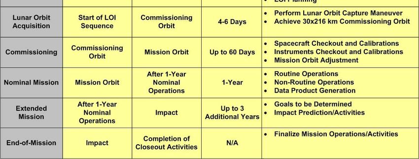
pearing on cable news networks
networks, showing
ing detailed images of landing hardware and faint but visi-
vis
2
ble footprints left by Apollo astronauts .
Figure 1.. LRO mechanical drawing, with spacecraft body coordinate system (BCS) identified
This paper begins with an overvi
overview of the GN&C subsystem and a discussion of the LRO
mission timeline. An early mission chronological narrative follows, describing GN&C subsystem
performance and interesting GN&C events (including some unexpected safe mode entries) that
occurred over a period from separation to cruise to lunar orbit
it insertion and the spacecraft com-
missioning phase.
LRO GUIDANCE, NAVIGATION AND CONTROL SUBSYSTEM
LRO’s GN&C subsystem is made up of an onboard d attitude control system (ACS), a
collection of software algorithms based on high level and derived requirements
requirements,, and a hardware
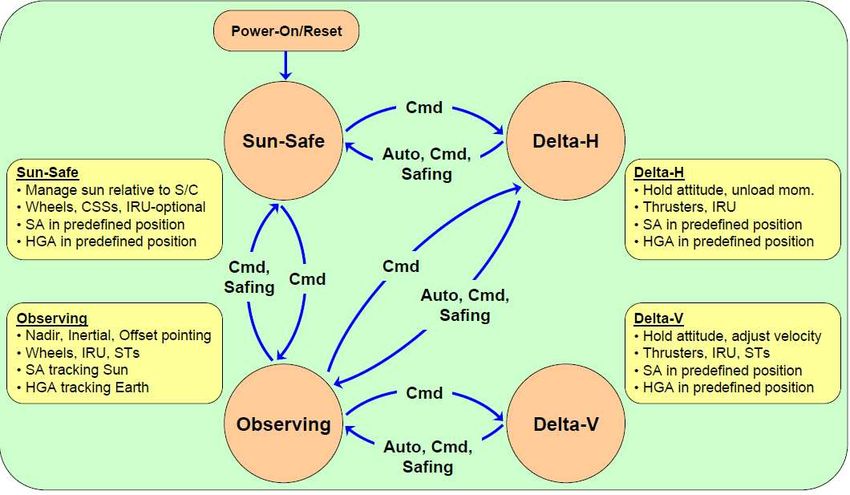
suite of sensors and actuators. Figure 2 shows the LRO control modes,, a brief description of their
t
functions, hardware required and the transitions between each mode. Transitions are defined as
automatic based upon defined criteria (Auto), commanded from ground or onboard algorithm
(Cmd), or as the result of an ano
anomaly (Safing). A discussion of eachach control mode and the
hardware suite follows.
Figure 2. ACS Mode Transition
2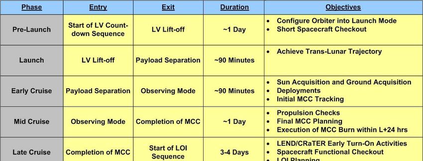
Primary Attitude Control Mode - Observing Mode
    Observing mode is LRO’s primary attitude control mode, which provides full-sky 3-axis
spacecraft attitude slewing and fine pointing for lunar nadir and off-nadir as well as inertial tar-
gets3. This control mode is used for all nominal pointing and slewing operations including those
for science data taking, instrument calibration, as well as initial attitude acquisition during Delta-
V mode operation. The hardware complement used for this mode includes four reaction wheels
(RW), two star trackers (ST), and one 3-axis inertial reference unit (IRU). Two quaternion output
STs are operated continuously, providing a highly accurate attitude reference to ensure attitude
performance during occasional single star tracker occultation. Attitude and rate sensor data is
processed onboard using a six-state Kalman filter4, which estimates IRU bias and spacecraft iner-
tial attitude quaternions. The filtered quaternion data is used as the attitude source for onboard
attitude control as well as the definitive spacecraft attitude for ground processing of science data.
Control torque commands are generated using a standard PID type control law. This algorithm
utilizes quaternion feedback proportionally-limited attitude error to ensure that all slews closely
track the eigenaxis with a constant slew rate. An attitude limit is set to ensure ample torque mar-
gin at a slew rate of 0.1 deg/sec over the design system momentum range of 80 Nms.
Thruster Maneuver Mode – Delta-V and Delta-H
    Cruise trajectory, mid course correction, lunar orbit insertion, and orbit maintenance maneuv-
ers are accomplished using a GSFC in-house developed propulsion system to adjust the space-
craft’s velocity magnitude and vector direction. The system utilizes four 20-lbf thrusters (inser-
tion thrusters or NT) and eight 5-lbf thrusters (attitude thrusters or AT) for orbit adjustments and
attitude control during maneuvers. The NTs are reserved for providing orbit adjust for the lunar
orbit insertion maneuvers following a trans-lunar cruise phase. The ATs are used for attitude
control and/or orbit adjustment during all phases of the mission. Delta-V mode uses a PID con-
troller to generate thruster torque commands for attitude control during orbit adjust operations.
This mode uses an IRU propagated attitude for feedback control since the higher body rates and
accelerations during propulsion may be too large to maintain reliable star tracker operation.
Spacecraft angular velocity measurements from the IRU are also used for rate feedback in the
Delta-V controller. Performance for this mode varies with the operational events during the mis-
sion lifetime. The performance requirement is averaged over the burn period because there are
initial transient periods of high rate and attitude errors that settle out over time. To improve the
transient response and settled attitude errors, a feed-forward torque, estimated based on thruster
configuration and spacecraft mass properties, was added.
    The ACS also provides for a thruster based system momentum management algorithm (known
as Delta-H) to maintain the system and wheel momentum to within acceptable levels. Delta-H
employs a similar algorithm as Delta-V, with the two differences being the method for computing
the reaction wheel commanded torque and the removal of the integral term. Each reaction wheel
is actively commanded in the controller to a commanded momentum level. A system momentum
level command is also used to determine when the targeted momentum level has been reached, to
within some acceptable tolerance. The ATs are used to maintain attitude pointing while the
wheel and system momentum is ‘dumped’. At the completion of the maneuver, the system re-
verts back to the mode from which Delta-H entered, typically Observing mode.
Spacecraft Safe Hold Control – SunSafe and SunSafe Gyroless
   A coarse sun-pointing mode (SunSafe) is responsible for initial attitude acquisition, and in the
event of a perceived spacecraft anomaly, providing a sun-pointing, power and thermally safe, atti-
tude for an indefinite period of time. SunSafe mode makes use of ten coarse sun sensors (CSS) to

                                                    3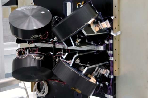
determine a sun vector, and an IRU to determine the spacecraft angular velocity in the body
frame. Through use of reaction wheels, SunSafe mode provides full-sky reorientation to a sun-
pointing attitude along a ground supplied target sun vector in the body frame. To reduce the mo-
mentum accumulation due to solar radiation torques, a rate bias is commanded, resulting in a
spacecraft roll about the sun target vector.
    Nominally, SunSafe utilizes CSS and IRU data for feedback control, but in the event of an
IRU failure, also includes a gyroless sub-mode. SunSafe Gyroless exists to compute rate infor-
mation from the CSS data alone. Since the IRU is no longer in the feedback loop, the spacecraft
rate about the sun line cannot be determined. Therefore, sun-pointing is maintained without con-
trol about the sunline. Another difference in these safe hold modes is that during eclipse; Sun-
Safe Gyroless does not have attitude or rate feedback so the spacecraft is allowed to drift until sun
presence returns (essentially open-loop control during eclipse).
Adcole Coarse Sun Sensors
    The most basic sensors used on LRO to determine
spacecraft attitude are ten Adcole coarse sun sensors.
These small devices collect sunlight and convert the
amount of sunlight into an electrical current. That cur-
rent level is then translated into a digital signal, which
is then processed by the onboard flight software. The
amount of sunlight produced by each CSS is a measure
of the angle between the line to the sun and the bore
sight of the CSS. When combined with other CSS
measurements, a three dimensional estimate of where
the Sun is relative to the spacecraft body frame is             Figure 3. Adcole CSS mounted on
computed.                                                             LRO Solar Array
    While relatively simple, these sensors are extreme-
ly important to the health and safety of the spacecraft. These devices are very small, relatively
inexpensive, yet their input is the key to providing an attitude input to SunSafe. Without them
working correctly, having the spacecraft thermally and electrically safe is questionable.
SELEX Galileo Star Trackers
    Fine pointing attitude determination is accomplished by two SELEX Galileo Star Trackers.
These STs have a 16° x 16° field of view and produce a quaternion attitude solution in the ST
frame with respect the J2000 Earth Centered Inertial reference frame. Each tracker produces an
attitude solution at 10 Hz but for the LRO application is read and processed at the ACS cycle of 5
Hz. Both trackers receive a one pulse per second (PPS) timing synchronization input from the
spacecraft’s onboard oscillators (clocks) and have their own 1553 Remote Terminal address for
independent operation.
    Star tracker processing includes a derived rate option that filters a differentiated quaternion
output from the tracker in the event that the IRU onboard the spacecraft becomes unavailable.
These derived rate measurements serve as a backup rate during critical Delta-V operations and
can allow the Observing mode to function, albeit with degraded performance, to continue science
instrument data collection and calibration.
Honeywell Miniature Inertial Measurement Unit
    Honeywell’s Miniature Inertial Measurement Unit (MIMU) serves as a single IRU. It con-
tains 3 ring-laser gyros (one gyro per axis) that are used to produce spacecraft inertial body rates.

                                                    4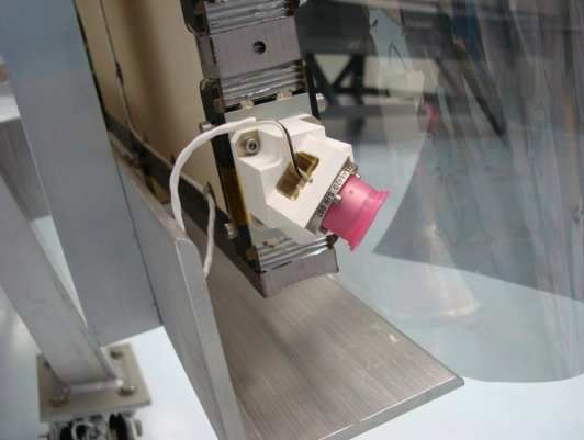
This unit outputs an accumulated angle, which is sam-
pled by the onboard system at 10 Hz and differenced
to produce the body rates. These 10 Hz rate estimates
are averaged over two samples to provide a rate for
use in the feedback loop at the ACS cycle time of 5
Hz. Due to accumulated angle roll-over ambiguity,
the MIMU gyros provide only direction of spin but
not the magnitude of the attitude rate for rates above a
saturation level. For LRO the IRU saturation level is
18 deg/sec. The MIMU was turned on prior to launch
and, has performed flawlessly in continuous operation
during the LRO mission.                                        Figure 4. MIMU mounted on LRO

NASA GSFC Demiseable Integrated Reaction Wheels
   Fine pointing control of the LRO spacecraft is
accomplished through the use of four Reaction
Wheels (RWs). These actuators were developed,
built, tested, and delivered in-house by the
NASA Goddard GN&C Hardware Branch. Each
RW uses an 18-inch aluminum flywheel, provid-
ing inertia for momentum exchange. The RWs
are mounted in a pyramid configuration with a
reaction wheel assembly system momentum sto-
rage capacity of 130 Nms.
   The LRO RW contains several design fea-
tures. Each wheel has software and firmware for             Figure 5. Reaction Wheel Assembly
controlling either wheel speed or wheel torque as mounted on LRO in a tetrahedron configura-
well as the reporting of telemetry. Each wheel                            tion
also has a separate 1553 Remote Terminal ad-
dress. The internal software and firmware can be reprogrammed from the ground if desired dur-
ing the mission. Although not used for this lunar mission, the wheel design has the added feature
of nearly complete burn-up if it were to plummet into the Earth’s atmosphere at the end of its life.
Propulsion Deployment Electronics
    The Propulsion Deployment Electronics
(PDE) has a number of functions used to com-
plete the LRO mission. First, the PDE com-
mands the firing of the thrusters when desired
as well as firing of the Propulsion NASA Stan-
dard Initiators (NSI) for opening of the propul-
sion pressurization tank. During the Solar Ar-
ray (SA) and High Gain Antenna (HGA) dep-
loyment, the PDE is used to turn on the Non
Explosive Actuators (NEA). Additionally, the
PDE prevents the radio frequency transmitters
from functioning until launch vehicle fairing
                                                                    Figure 6. PDE
separation, and provides extra switch capabili-
ties for science payload heaters. This component was designed to allow the propulsion system to
have redundant drive electronics to support the redundant set of thrusters. The PDE is designed

                                                    5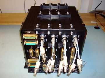
with four identical electronic boards and one module for the prevention of certain spacecraft func-
tions at the desired times.
   The design of the four PDE electronic boards allows for the critical Lunar Orbit Insertion
(LOI) maneuvers to be completed, even if one of the four identical electronic boards is declared
suspect. Each of the four electronic boards has their own 1553 remote terminal address. The
thrusters are connected to electronic boards in a manner that allows LRO to complete its desired
orbit adjustment despite a thruster failure.

LRO MISSION TIMELINE
    The first twelve hours of the flight were packed with action (refer to Table 1). Immediately
after separation, SunSafe, the default control mode, autonomously removed the tip-off rates and
placed the spacecraft in a power-positive orientation. Afterwards, the deployables were extended
to put the spacecraft in its flight configuration. The GN&C hardware as well as other subsystems
were powered on, and the ACS mode was transitioned to Observing mode. Thruster one-shots
were performed to ensure thrusters were working, and the communication was switched from
omni-directional antenna to the HGA.
    One day after launch, LRO conducted a mid course correction maneuver to adjust the inclina-
tion of its orbit. After the mid course correction, LRO cruised towards the moon with little ex-
citement for three days. On the fifth day after launch, June 23, 2009 at 6:26:26am EDT, LRO
completed a flawless LOI maneuver to place itself in an elliptical orbit about the Moon (Figure 7
shows the various phases of LRO’s orbit during its mission: initial trajectory, LOI, commission-
ing orbit, and nominal orbit). Over the next five days, four more LOI maneuvers transferred LRO
into its commissioning orbit.
    Over the next ten weeks, the spacecraft and instrument teams commissioned their respective
systems. Commissioning was when the GN&C Team had a chance to test out its primary attitude
control mode as well as calibrate all of its systems. Once commissioning was completed, a series
of thruster maneuvers, mission orbit insertion (MOI), lowered LRO into its nominal 50 km mean
mission orbit where it began collecting meaningful science data.

                                     Figure 7. LRO Orbit Phases

                                                  6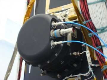
Table 1. LRO Mission Timeline

MISSION CHRONOLOGY

SUN ACQUISITION
   LRO separated from the Atlas V launch vehicle with tip-off rates of approximately [-0.1, 0.2, -
0.8] deg/sec in the x,y, and z axes, respectively. Figure 8 shows the autonomous acquisition of
the Sun by the SunSafe control mode. Shown are the spacecraft rates and spacecraft body sun
vector. During the separation, the spacecraft was in a sun-avoidance state, which seeks to keep
the sun off of the spacecraft +Z-axis, to avoid instrument illumination. SunSafe simultaneously
removed the tip-off rates, as well as began maneuvering the spacecraft so the Sun is on the -Z-
axis. Once sun-avoidance was exited, SunSafe began maneuvering the spacecraft to point the
folded SA towards the Sun (SA on the –Y-axis). The presented data shows that it took approx-
imately 8.5 minutes to acquire the Sun after separation.

                                                 7
Figure 8. Spacecraft Angular Velocity and Sun Vector during Sun Acquisition. The Sun target is
the –Y spacecraft axis – i.e. a target vector of [0,-1,0].
CRUISE
This section details GN&C activities after sun acquisition until lunar orbit acquisition. Fifty
minutes after separation, the SA was deployed to increase power accumulation. Twenty-five mi-
nutes later, the HGA boom was deployed to put the spacecraft into its deployed configuration.
Five minutes after deployments were completed, the star trackers were turned on and the ACS
control mode was switched from SunSafe to Observing for the first time. Immediately after-
wards, the GN&C Team ran a thruster one-shot test, where each of the eight ATs and each of the
four NTs were pulsed one time while the spacecraft was holding an inertial attitude. These one-
shot tests demonstrated that thruster performance was within specified tolerance of all pre-
planned metrics.
Solar Array and High Gain Antenna Deployment
The Mechanical subsystem team requested that the GN&C team monitor the IRU rates in
hopes that this data would help to verify proper deployment of the HGA and SA. In particular,
they were interested in assessing proper functioning of the deployment latch mechanisms. While
it was not possible to absolutely verify proper functioning of the latch mechanisms using IRU
data alone, it was thought that careful inspection of the rate data would provide some corroborat-
ing evidence of proper deployment. Figure 9 presents the spacecraft angular velocity during the
SA and HGA deployments. The deployment process began with the firing of a non-explosive
actuator, which released the SA from the spacecraft. To allow the SA panels to unfold, the SA
was mechanically driven to an extended position (identified as (90,-45) degrees). During this
time, the two panels began to unfold with the assistance of spring mechanisms. The SA panels
latched into place when they reached their deployed positions. Afterwards, the SA was driven
back to its ‘index’ position, identified as (90, 45) degrees. A few minutes later, the HGA boom
8was released from the spacecraft body and extended to its deployed configuration with the aid of
a non-explosive actuator and a spring-loaded mechanism. A latch engaged when the HGA boom
arrived at its deployed position.
Figure 9. Spacecraft Angular Velocity during Deployments
During both deployments, a system momentum rate of change safing action point (AP) was
tripped in the Fault Detection and Correction System (FDC). The system momentum rate of
change limit was set to 3.3 Nm and the action point trips if the limit is exceeded for more than 3
seconds. As can be seen in Figure 10, the limit is exceeded for more than 3 times on a few occa-
sions during the deployment sequence. The original purpose of this safing action point was to
detect and prevent system momentum from growing too fast to handle with wheels, and to pre-
vent fuel loss. When this AP tripped, the FDC commanded the spacecraft to isolate the propul-
sion system, transition to SunSafe, and stop any activities occurring on the spacecraft. In the dep-
loyment situation, there were no issues with the propulsion system because none of the isolation
valves were open and the spacecraft was already in the SunSafe control mode.
9Figure 10. Spacecraft System Angular Momentum Rate of Change during Deployments
First Anomalous Entry into SunSafe
The spacecraft’s first anomalous entry into SunSafe occurred soon after the thruster checkout
and during the first transition into Observing mode. The transition into SunSafe was caused by
not having ephemerides loaded to the spacecraft. During nominal operations, the spacecraft ge-
nerates the target attitude using an on-board ephemeris uploaded from the ground. However, dur-
ing early operations, the spacecraft was using a ground uploaded target attitude and therefore
ephemerides were not needed. Unfortunately, the safing configuration did not check to see what
the target source was and automatically transitioned the spacecraft back into SunSafe. There was
very little impact to the spacecraft operations due to this event, and no further action was re-
quired.
Observing Mode Checkout
Shortly after the thruster one-shot tests and spacecraft appendage deployment were successful-
ly completed, a series of attitude slews were performed using the Observing mode controller to
provide an initial set of data for calibration of the IRU bias, alignment, and scale factor. This
“mini-cal” of the IRU was followed up later with a more precise IRU calibration involving a se-
ries of large angle slews over several hours. At this time, a relative ST calibration was also per-
formed using ST quaternion data to compute corrections to ST alignments, removing any resi-
duals between the ST quaternion outputs. This corrected a known error in the ST alignment,
loaded at launch, which was on the order of a few tenths of a degree. Calibration parameters
were uploaded to the spacecraft, and the onboard attitude Kalman Filter (KF) was initialized for
the first time using measured data from both STs. During the cruise phase, both STs were operat-
ing with nominal performance and the KF remained converged with a steady-state attitude esti-
mation error covariance of approximately 2 to 3 arc-sec (1 sigma). Since fine pointing perfor-
mance was not needed during the cruise phase, the KF output was not used for attitude feedback
or for IRU bias correction. Instead, a ST was selected as the attitude source and a constant bias
correction was applied to the IRU rates used for feedback control. This provided the team with
10the opportunity to trend the KF performance during the transit to the moon before utilizing KF
output in the feedback, as required for fine pointing performance during the rest of the mission.
Figure 11 shows a plot of typical attitude errors during cruise, when the attitude feedback was set
to the ST output. Note the boresight of this ST is aligned within about 30 deg from the spacecraft
Z-axis and perpendicular to the X-axis of the spacecraft. Thus, the larger ST errors about the bo-
resight result in relatively larger attitude errors about the Z and Y axes.
Occasionally, the attitude source was set to IRU propagation. This was primarily done in
preparation for Delta-V operations and during ST occultations, which occurred when the space-
craft maintained inertial attitude during initial lunar orbit operations. This gave the team a chance
to observe the best controller performance that could be achieved when targeting inertial attitudes
with minimal disturbances present. Figure 12 shows typical 1 arc-sec level attitude error perfor-
mance attained using IRU propagation as attitude feedback, when the SA was fixed, no spacecraft
instruments were moving, and the reaction wheels were at low momentum levels. The data from
Figure 12 was captured on Day of Year (DOY) 174. Attitude error when the IRU propagation
was used as the attitude source, during inertial attitude targeting, demonstrated the best controller
performance that was to be expected when the KF was used as the attitude source.
Figure 11. Typical Attitude Error when ST selected for Attitude Feedback during Cruise
11Figure 12. Best Attitude Performance Using IRU Propagation During Cruise Phase (DOY 174)
LUNAR ORBIT ACQUISITION
The LRO spacecraft performed a series of seven thruster maneuvers to reach the spacecraft’s
commissioning orbit with the first and third maneuvers being critical and the third maneuver the
most critical. This section discusses the first maneuver, Mid Course Correction 1, and the third
maneuver, Lunar Orbit Insertion 1.
Mid Course Correction 1
Mid Course Correction 1 (MCC-1) was performed on June 19, 2009, approximately 24 hours
after launch and lasted about 48 seconds. MCC-1 used 4 out of the 12 thrusters on-board the
spacecraft in an off-pulsing configuration. The maneuver executed flawlessly and phase plane
plots of the maneuver are shown in Figure 13. The horizontal axis of each subplot represents the
attitude error and the vertical axis of each plot represents the rate error seen by the Delta-V con-
troller. The maximum absolute attitude error was 0.57 deg and the maximum absolute rate error
was 0.13 deg/sec.
12Figure 13. Mid Course Correction Maneuver Phase Plane Attitude and Rate Error
Lunar Orbit Insertion 1
The third Delta-V maneuver performed by the spacecraft was Lunar Orbit Insertion 1 (LOI-1).
LOI-1 was the longest thruster maneuver executed by the spacecraft, 40 minutes, and used all 12
of the thrusters on the spacecraft. The 4 NTs were full on, and the 8 ATs were controlled in an
On-Pulsed Mode. LOI-1 was used to slow down the spacecraft in order to be captured by the
Moon’s gravitational field. Any issues with this critical maneuver could have resulted in a de-
graded science mission or loss of mission. This maneuver executed flawlessly with small attitude
and rates errors as shown by the phase plane plots in Figure 14. The maximum absolute attitude
error was 3.2 deg and the maximum absolute rate error was 0.36 deg/sec.
Figure 14. Lunar Orbit Insertion Maneuver Phase Plane
13A time history of the attitude error during the LOI-1 maneuver is shown in Figure 15. As
shown in the figure, an initial transient was seen in the controller and these errors were damped
out within a couple of minutes in the x and y axes and within 10 minutes in the z axis.
Figure 15. Lunar Orbit Insertion Maneuver Time-History Attitude Error
Second Anomalous Entry into SunSafe
Another unexpected entry into SunSafe mode occurred during the first lunar orbit after LOI-1.
Both STs were occulted by the Moon for a duration of 1 hour. This was expected since the LRO
had not yet started Nadir targeting operations and the onboard target was inertial. Both STs en-
tered standby mode when the ST data was marked as invalid during the lunar occultation. The
attitude source was set to ST1 at this time, so the onboard attitude was IRU propagated from the
last valid ST1 quaternion (just prior to Moon occultation). The FDC system includes monitors
for each ST operational mode. If either ST’s operational mode is “standby”, then it is com-
manded back into the autonomous attitude determination (AAD) mode at 1 minute intervals,
causing the ST to attempt to re-acquire the attitude from a “lost in space” condition. During one
of these attempts to promote ST1 from standby mode to AAD mode during the occultation, ST1
computed a “valid” quaternion, with also a “valid” rate, for a single ACS cycle. This “valid” qua-
ternion had a very large error in excess of 100 deg. But, since it was marked as valid, it was
processed by the onboard system for use. An additional delta quaternion check, which compares
the ST quaternion to a valid one from the previous cycle, failed to catch the error since the pre-
vious cycle was marked as invalid. As a result, this single piece of inaccurate attitude data was
used as the attitude source for one ACS cycle. After this cycle, the ST data immediately became
invalid again, and the ST dropped back into standby mode. So, the onboard attitude was again
the IRU propagated attitude, but unfortunately propagated from this erroneous ST quaternion
(which had been marked as “valid”). Thus, the onboard attitude solution remained inaccurate,
thereafter and the onboard FDC sent LRO into SunSafe due to the persistent large attitude error.
LOI 2 through LOI 5
The remaining LOI maneuvers were accomplished using the same two NTs and all eight of the
ATs. With each successive maneuver, the GN&C Team estimated a new feed forward torque to
apply to the controller in order to reduce the initial attitude transient. Table 2 shows the maxi-
14mum attitude error and rate error the spacecraft saw during each maneuver. Notice that the max-
imum attitude error decreased with each successive maneuver.
Table 2. LOI-2 to LOI-5 Performance
Max Abs Attitude Error (deg) Max Abs Rate Error (deg/sec)
Maneuver X Y Z X Y Z
LOI-2 0.65 1.46 1.16 0.11 0.12 0.28
LOI-3 0.06 0.92 0.27 0.02 0.20 0.07
LOI-4 0.07 0.83 0.20 0.02 0.21 0.07
LOI-5 0.06 0.78 0.21 0.04 0.20 0.08
COMMISSIONING
During the Commissioning phase of the mission, LRO engineers and scientists checked-out
and calibrated their respective systems. The operations team planned and executed a number of
off-point maneuvers to accommodate the science and engineering teams. During this time, the
SA unexpectedly hit a gimbal lock situation. Also, the Observing mode control mode was tested
in great detail and disturbances causing attitude transients were studied and understood.
Solar Array Gimbal Lock Event
The SA encountered a gimbal lock situation on July 1, 2009 when the sun target vector ap-
proached [0,-1,0], i.e., when the sun is directly on the –Y-axis of the spacecraft based on up-
loaded ephemeris. This happens because there are an infinite number of possible solutions for
that particular array orientation. Observed performance showed the commanded SA Gimbal 1
angle swerve, stop, turn around, and continued to swerve for an orbit; refer to Figure 16. Since
the spacecraft was flying with a 30 degree offset (for thermal reasons), the SA really was not at
the gimbal lock orientation. But, the SA targeting algorithm uses a target sun vector (computed
from on-board ephemeris) instead of the measured sun vector. Therefore, when the target sun
vector became [0,-1,0], the algorithm detected gimbal lock. However, the observed flight beha-
vior was not seen during testing, which led to a deeper study of the event.
The SA targeting algorithm determines gimbal lock by comparing the target vector to a toler-
ance value. When that tolerance value is set properly, gimbal lock is identified early and the SA
is sent to a pre-defined angle of + 90 deg for gimbal 1. Flight results show that gimbal lock was
not detected early. Gimbal 1 was commanded to +90 deg, but then exited gimbal lock and pro-
ceeded to follow a swerving command. This means that the tolerance value was not set properly
(it’s a table value – current value is 1x10^-16 rad and it should be 1x10^-10 rad). Figure 16 shows
the expected behavior with the correct tolerance setting, “HiFi Predicted Ang”.
15Figure 16. Array Gimbal Lock Event plotted against High Fidelity Simulation Results
The easiest solution to prevent the observed performance when gimbal lock is encountered
again is to change the tolerance value to 1x10^-10 rad. But this requires the creation, testing and
uploading of a new table. Gimbal lock only occurs when the spacecraft is at a high solar beta
angle, and since the nominal operational plan is to park the SA at high solar beta angles, this situ-
ation should never occur again. The reason it was encountered is because the nominal SA opera-
tional plan was not being followed.
Observing Mode Performance
LRO demonstrated excellent pointing performance during Observing mode nadir and inertial
attitude target operations during the entire Commissioning phase. LRO pointing requirements are
given as pointing accuracy and knowledge relative to the prime ST reference frame. Since there
is no direct measure of pointing accuracy relative to this frame, the derived attitude control error
requirement of 15 arc-sec (3 sigma), consistent with the LRO knowledge and attitude accuracy
requirements, was used to access pointing performance.
Transient LRO attitude errors observed during commissioning, shown in Figure 17 and Figure
18, resulted primarily from three sources: Diviner instrument calibrations, RW zero crossings,
and SA articulation. A description of each of these disturbances is documented in the subsections
below.
An additional error source seen in Figure 17, which will not be described in detail, was due to
a non-constant nadir target rate resulting from the low-lunar-elliptic commissioning orbit. A
small amplitude pitch error variation at the orbit period of 2 hours exists. This sinusoidal varia-
tion of attitude error of about +/- 2 arc-sec, was eliminated after LRO was maneuvered into the
nearly circular mission orbit.
Even during times of considerable disturbance, primarily due to RW zero crossings and SA ar-
ticulation as shown in Figure 18, the attitude errors were maintained below the statistical attitude
error requirement level of 15 arc-sec (3 sigma) as documented in Table 3.
16Figure 17. Attitude Error during DOY 189, 00:00 GMT
Diviner Instrument Calibration Disturbance. Figure 17 shows attitude error for a typical orbit
during nadir target operations on DOY 189 during times when the SA is not moving and RWs do
not cross zero speed. Attitude errors remain below 2 arc-sec, with the exception of transients
caused by Diviner instrument motion. There are two types of Diviner motion that caused space-
craft pointing error. The smaller disturbance was caused by a “barrel roll” or elevation-only gim-
bal motion for pointing the instrument to deep space for calibration. These occurred at 10 minute
intervals and resulted in less than 5 arc-sec pointing error, primarily about the spacecraft roll axis.
The other Diviner disturbance is a result of two axis motion of the Diviner azimuth and elevation
gimbals occurring once per orbit. The effective inertia load of the azimuth gimbal is much larger
than that of the elevation gimbal. Thus, the corresponding spacecraft attitude disturbance, pri-
marily about the spacecraft yaw axis, is larger respectively, as shown in Figure 17 at approx-
imately 67 minutes. The Diviner azimuth disturbance is clearly present at time = 470 minutes
and has an amplitude of approximately 23 arc-sec, refer to Figure 18.
Reaction Wheel Zero Crossing Disturbance. Data taken during DOY 220 (Figure 18) shows
somewhat increased pointing errors during the times when the SA is tracking the Sun and the
RWs are crossing zero speeds. The disturbances at time = 430, 442, 464, 470, 493, 497 minutes,
and during period from time = 520 to 530 minutes are all caused by reaction wheel zero cross-
ings. Worst case transients from wheel #3 cause pointing error transients of ~50 arc-sec as shown
in Figure 18 at time=465 min. Wheel speed zero crossings continued to occur each orbit as X-Z
momentum increased at higher rates than pitch axis momentum. During subsequent Delta-H
wheel momentum unloading, pitch momentum biasing was used to minimize low speed wheel
operation while maintaining system momentum within 80 Nms over a required two week period.
Although using this strategy, it was not always possible to entirely avoid zero crossings within the
system momentum constraints.
Solar Array Elevation Gimbal Step Disturbance. On DOY 220 attitude transients apparent at
time = 427, 437, 480, and 500 min were due to SA elevation angle command step transients, Fig-
ure 18. Generally, the SA elevation gimbal is stopped or moving somewhat slowly during nadir
17target operations. Integrator wind-up in the SA gimbal controller resulted in instantaneous SA
motion of about two cardinal steps (0.015 deg). These disturbances resulted in rate transients of
about 30-40 arc-sec/sec about roll axis and 20-30 arc-sec/sec about yaw axis, as shown in Figure
19. These rates were somewhat large, but still within the LRO stability requirements. Options
for elimination of this disturbance are to zero out the integrator gain or to reduce the integral lim-
its in the SA elevation controller, neither of which was implemented during the commissioning
phase.
Figure 18. Attitude Error during DOY 220, GMT 07:00
Solar Array Harmonic Drive Gear Transmission Error Disturbance. Figure 18 also shows
typical attitude error response due to SA harmonic drive gear transmission error, primarily about
the pitch axis. This error is caused by a sustained SA oscillation driven at harmonics of the SA
gimbal drive speed. The dominant disturbance occurred at a 2x harmonic of the SA rate, with a
period of approximately 15 to 20 sec due to the rather high 200:1 gear ratio of the drive system.
This effect resulted in a maximum attitude error of ~11 arc-sec over a typical orbit, shown in Fig-
ure 18 on DOY 220. This maximum error coincides with the SA rewind when the SA azimuth
gimbal reverses direction at time = 470 min. While this error was predicted prior to flight, it was
somewhat surprising that the magnitude of the error seemed to be dependent on the direction of
gimbal rotation and perhaps the loading of the gears during the reversal. Note that the error de-
creases as the SA continues to rewind after time = 480 min. This gear transmission error has
been trending somewhat lower as the solar beta angle decreases, as a result of the decreased iner-
tia loading about the +Y gimbal axis.
Solar Array Rewind Disturbance. Since LRO is Nadir pointing in a polar orbit, the SA +Y
gimbal reverses direction twice an orbit over the lunar poles. The attitude disturbance resulting
from this SA “rewind” is minimized by using acceleration profiling. As the SA approaches the
rewind condition, the gimbal rate is slowly reduced to zero over a period of about two minutes.
After a few minutes in a stopped condition the SA rotation is reversed and the rate is slowly in-
creased, again over a two minute period. The effect of this rewind disturbance can be seen in the
body rate plot for DOY 220, Figure 19, at time = 465 and 525 min. As shown in Figure 19, max-
18imum rates from this disturbance were about 20 arc-sec/sec. These rate spikes occur at the end of
deceleration and beginning of acceleration from a stopped condition due to the drive having a
non-zero minimum rate. Figure 18 shows that the attitude transients due to SA rewind was typi-
cally less than 10 arc-sec.
Figure 19. Rate Error during DOY 220, GMT 07:00
Table 3. Observing Mode Controller Error Statistics
Roll Pitch Yaw
(arc-sec, 3 sigma) (arc-sec, 3 sigma) (arc-sec, 3 sigma)
Nadir with SA fixed and no RW
2.2 5.3 2.8
zero crossings (DOY 189)
Nadir with SA tracking and RW
13.8 10.9 7.1
zero crossings (DOY 220)
Requirement 15.0 15.0 15.0
CONCLUSION
This paper detailed experiences from the Guidance, Navigation and Control (GN&C) Team
during launch through commissioning of the Lunar Reconnaissance Orbiter (LRO). An overview
of the GN&C subsystem was followed with a brief discussion of the mission timeline. An early
mission chronological narrative described the GN&C subsystem performance and interesting
GN&C events. Spacecraft angular velocity data showed that the initial attitude acquisition, fol-
lowing launch vehicle separation, was successful. Flight telemetry received both in real time and
stored for later downlink demonstrated excellent GN&C system performance. With the exception
of a few anomalous entries into SunSafe mode, the system operation was flawless. These safe
hold transitions, while unplanned, provided the team a unique opportunity to demonstrate the re-
liability of SunSafe mode and recovery operations.
19Assisting in the early LRO mission and spacecraft commissioning provided the GN&C team
invaluable experience operating a spacecraft being inserted into Lunar orbit. We are all very
proud and grateful to have had the privilege to participate in this historic NASA return to the
Moon. Currently, LRO is conducting its nominal science mission collecting much needed data
for NASA’s eventual return to the Lunar surface.
ACKNOWLEDGMENTS
The authors would like to acknowledge the rest of the GN&C Team: Jason Badgley, Kristen
Brown, Nat Gill, Russ Roder, Noble Jones, John Wilson, Wattana Kern, Kenneth McCaughey, Ed
Davis, J. Roger Chen, Gerardo Cruz-Ortiz, Juan Raymond, and Eric Holmes, for their hard work
and enthusiastic dedication to the LRO mission
REFERENCES
1
LROUpdate.Blog, http://lroupdate.blogspot.com, accessed January 12, 2010.
2
LRO Mission Webpage, http://www.nasa.gov/mission_pages/LRO/main/index.html, accessed January 12, 2010.
3
Calhoun, P.C., Garrick, J.C., “Observing Mode Attitude Controller for the Lunar Reconnaissance Orbiter,” 20th In-
ternational Symposium on Space Flight Dynamics, Annapolis, Md., September 24-28, 2007.
4
Lefferts, E.J., Markley, F.L., Shuster, M.D., “Kalman Filtering for Spacecraft Attitude Estimation,” Journal of Guid-
ance, Volume 5, No. 5. AIAA 82-0070R, American Institute of Aeronautics and Astronautics, 1982.
20You can also read