OPERATOR'S MANUAL - GI Direct
←
→
Page content transcription
If your browser does not render page correctly, please read the page content below
O P E R A T O R ’ S M A N U A L
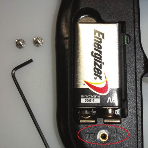
TABLE OF CONTENTS
      WARNING!
This is not a toy. Misuse may cause serious injury or death. Eye protection designed specifically for                                                   Specifications......................................................................................................Page 1
paintball must be worn by the user and persons within range. Must be 18 years of age or older to
purchase. READ AND FOLLOW THIS MANUAL BEFORE USING.
                                                                                                                                                        Basic Operation...................................................................................................Page 2

                WARNING! PAINTBALL GUNS AND PAINTBALL GUN
                         ACCESSORIES ARE NOT TOYS!
                                                                                                                                                        Firing the Axe.......................................................................................................Page 3
   - Careless use or misuse may result in serious bodily injury or death!
   - Eye protection designed for paintball must be worn by the user and all persons within range.                                                       Break Beam Eyes Operation..............................................................................Page 3
   - Not for sale to persons under 18 years of age.
   - Must be 18 years of age or older to operate or handle any paintball gun and paintball gun accessories without adult or parental supervision.
   - Read and understand all cautions, warnings, and operating manuals before using any paintball gun or paintball gun accessory.
   - Do not aim paintball gun at eyes or head of people or at animals.                                                                                  Regulator and Velocity Adjustment...................................................................Page 4
   - Paintball guns are to be used with Paintballs only.
   - To prevent fire or shock hazard, do not expose unit to rain or moisture.
   - To prevent fire or shock hazard, do not immerse unit in liquids.                                                                                   Shockwave Board Settings and Functions.......................................................Page 4
   - To prevent fire or shock hazard, do not disassemble any electronic paintball device.
   - The disposal of the battery used to power this product may be regulated in your area.
   - Pleaes conform to all local or state regulations with regard to battery disposal.
   - Use common sense and have fun.                                                                                                                     Assembly/Disassembly and Maintenance........................................................Page 7
   Any tampering with the unit voids your warranty. There ar no consumer serviceable parts inside the unit. The use of non factory authorized
   components within this product may cause a critical failure, fire or shock hazard.
                                                                                                                                                        Empire Regulator Service Guide.......................................................................Page 9
   IN NO EVENT SHALL SELLER BE LIABLE FOR ANY DIRECT, INCIDENTAL OR CONSEQUENTIAL DAMAGES OF ANY NATURE, OR LOSSES OR
   EXPENSES RESULTING FROM ANY DEFECTIVE PRODUCT OR THE USE OF ANY PRODUCT.
   WARNING: This product may contain one or more chemicals that are known to the State of California to cause cancer and birth defects or other         Solenoid Service Guide....................................................................................Page 11
   reproductive harm. Wash hands after handling. You must be at least 18 years of age to purchase this product. This product may be mistaken for
   a firearm by law enforcement officers or others. Altering the color of the product or brandishing the product in public may be considered a crime.
                                                                                                                                                        Storage and Transportation..............................................................................Page 11
                                                              Designed for Paintball use only.

                                                                                                                                                        Troubleshooting Guide.....................................................................................Page 12
Rules for Safe Marker Handling
WARNING: Never carry your paintball marker uncased when not on a playing field. The non-playing                                                         Diagram and Parts List.....................................................................................Page 14
public and law enforcement personnel may not be able to distinguish between a paintball marker and
a firearm. For your own safety and to protect the image of the sport, always carry your marker in a
                                                                                                                                                        Warranty Information........................................................................................Page 16
suitable marker case or in the box in which it was shipped.
• Treat every marker as if it were loaded.
• Never look down the barrel of a paintball marker.
• Keep the marker in “Safe Mode” until ready to shoot, power Off and barrel blocking device installed 		                                                SPECIFICATIONS
   in/on the marker’s Barrel.                                                                                                                           −   Engine: Pressure controlled poppet
• Keep your finger off the Trigger until ready to shoot.                                                                                                −   Barrel: Driver XX Aluminum Ported 2-piece .688
• Never point the marker at anything you don’t wish to shoot.
                                                                                                                                                        −   Caliber: .68
• Keep the barrel sock or another ASTM approved blocking device installed when not shooting.
• Always remove paintballs and the air source before disassembly.                                                                                       −   Action: Electro-pneumatic
• After removing the air source, point marker in safe direction and discharge until marker is degassed.                                                 −   Air Source: Compressed Air Only
• Store the marker unloaded and degassed in a secure place.                                                                                             −   Battery: One 9-Volt Alkaline
• Follow warnings listed on the air source for handling and storage.                                                                                    −   Cycle Rate: 20 BPS (Semi-Auto only)
• Do not shoot at fragile objects such as windows.                                                                                                      −   Main Body Material: Aluminum
• The operator and every person within range must wear eye, face and ear protection designed
                                                                                                                                                        −   Accuracy Range: 150+ ft. (45+ m)
   specifically to stop paintballs and meeting ASTM standard F1776.
                                                                                                                                                        −   Weight: 2.01 lbs. (911.7 grams)
• Always measure your marker’s velocity before playing paintball and never shoot at velocities in
   excess of 300 feet-per-second (91.44 meters-per-second).
• Read and understand this entire manual before loading, attaching a propellant source or in any way
   attempting to operate the marker                                                                                                                     Included with your Empire AXE
                                                                                                                                                        −   14” Driver XX Aluminum 2pc Barrel (.688 bore)
- Safety and safe marker handling are the most important aspects of paintball sports. Do not install 		                                                 −   Hex Keys
  compressed air or load paintballs into your AXE until you feel completely confident with your
                                                                                                                                                        −   Spare Parts Kit
  ability to handle your AXE safely.
- Keep your finger out of the Trigger guard and away from the Trigger; point the muzzle of the marker                                                   −   Barrel Sleeve
  in a safe direction at all times. Keep the marker turned off until ready to operate. The AXE uses an 		                                               −   One 9-Volt Battery
  On-Off button as one of its safety devices.
- Always keep your AXE pointed in a safe direction. Always use a barrel plug or barrel blocking device.
- Always use ASTM approved paintball specific eye protection in any areas where paintball markers
  may be discharged. Remember that the ultimate safety device is you, the operator.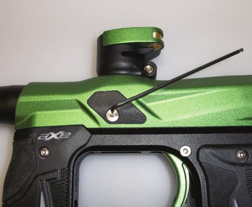
1. BASIC OPERATION                                                                                                                      3. Remove your air cylinder by slowly and carefully unscrewing it counter-clockwise. (Fig. 1b)
Barrel Installation
1. Make sure marker is degassed, loader removed, no paintballs in the feed port or breech and the
   marker is OFF.
2. Slide the longer barrel tip into the barrel back, turning the barrel tip clockwise until it stops (do not
   over tighten).
3. While pointing marker in a safe direction, thread the barrel into the front opening of the marker body.
4. Turn the barrel clockwise (when looking at the front opening) until it stops (do not over tighten).
5. Install a barrel blocking device. This can be a barrel bag or other such device that prevents the
   accidental discharge of a paintball.

HIGH PRESSURE COMPRESSED AIR TANK INSTALLATION                                                                                                                       (FIG. 1B)
The Empire AXE is designed to work with compressed air/nitrogen only. Do not use CO2, as it will
damage your marker. The Empire AXE utilizes a fully functional Regulator at the bottom of the grip                                      DE-PRESSURIZING THE MARKER
frame that doubles as an On/Off ASA (Air Source Adapter) or receiver for a standard threaded preset                                     1. Flip the On/Off lever forward and allow the gas to vent from the Regulator.
output compressed air system. The Regulator can function using either “high pressure” or “low                                           2. Air may remain within the marker once the Regulator is vented. While the barrel blocking device
pressure” air systems.                                                                                                                     is still installed, turn your AXE on, turn the eyes off and pull the trigger a few times to deplete all
                                                                                                                                           remaining air.
Note: If you are using an adjustable Regulator system, the output pressure should be set between 350-450 psi.                           3. Remove your air cylinder by slowly and carefully unscrewing it counter-clockwise.

BEFORE PRESSURIZING YOUR AXE MARKER                                                                                                     INSTALLING A LOADER AND PAINTBALLS
- Check to make sure that you and anyone within range are wearing eye protection designed                                               The Empire AXE uses .68 caliber, water-soluble paintballs, readily available at paintball pro-shops,
  specifically for paintball.                                                                                                           commercial playing fields, and many sporting goods stores. The paintballs feed from the loader
- Double check that all screws are tightened and no parts are loose before installing your tank.                                        through the feed-neck and into the breech of the marker.
- Ensure you have a barrel sock or other specifically designed barrel-blocking device in place.
- Make sure there are no paintballs in the marker and that the AXE is turned OFF.                                                       The Empire AXE comes equipped to accept standard-gravity feed loaders as well as most agitating
Notes:
                                                                                                                                        and force-feed loaders. Open the clamp lever and place the loader neck directly into the marker feed
- Remember compressed air or nitrogen systems can be extremely dangerous if misused or improperly handled. Use only cylinders 		        neck. Align the loader in line with the marker so the nose points in the same direction as the barrel.
   meeting D.O.T, TC. or regionally defined specifications. Do not perform any work to your tank or tank Regulator.                     Close the lever, noting that it might be necessary to adjust the feed-neck’s clamping screw to get a
- Never disassemble your tank or tank Regulator. Only a qualified and trained technician should perform work on your tank and tank
   Regulator.                                                                                                                           snug fit on your loader.
- Never add any lubricants or greases into the fill adapter on your tank Regulator
                                                                                                                                        POWERING ON YOUR AXE
PRESSURIZING THE MARKER                                                                                                                 • To switch the AXE On, locate the Power Button on the back side of the front Foregrip, in front of the
1. Flip the On/Off lever forward and allow the gas to vent from the Regulator. (Fig. 1a)                                                  Trigger guard and under the LED. (Fig 2-3)

      (FIG. 1A)                                                                                                                                                         (FIG. 2-3)

2. Air may remain within the marker once the Regulator is vented. While the barrel blocking device                                      •   Push and hold the button for 2 seconds. The LED will glow solid RED as soon as the button is
   is still installed, turn your AXE on, turn the eyes off and pull the trigger a few times to deplete all 		                               pressed. Continue to hold the button until the LED glows solid GREEN.
   remaining air.                                                                                                                       •   Release button and the LED will intermittently flash indicating that the marker is now ON and LIVE
                                                                                                                                            in FIRE Mode.
                                                                                                                                        •   The LED color will be determined by the battery level, as listed in the chart described under the
                                                                                                                                            Battery Life Indicator section of this manual.
                                                                                                                                        NOTE: Be sure not to have the Trigger pressed when turning the board on, as this will enter the board into Settings Mode.
                                                                                                                                                                                                                                                                    3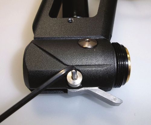
LED INDICATION AUTOMATIC OFF FEATURE
The LED indicator, located above the button, is used to indicate the current Break Beam Sensor The AXE also has an “Automatic OFF” feature. If you leave your AXE powered on, it will shut itself off
System status, the Battery Life Indicator and Trigger Pull indication. The Break Beam Sensor Status is after approximately 60 minutes of inactivity. This time cannot be adjusted.
indicated by the blinking frequency of the LED (See Section 5 for further explanation). If the Trigger is
being pressed the LED will glow a dim RED which can be seen between blinks of the LED. EYE FUNCTION
The AXE board is pre-programmed to activate the eye system each time the marker is powered up.
BATTERY LIFE INDICATOR See Section 4 (Break Beam Eyes Operation) for more details.
The AXE also has a Battery Life Indicator, shown by the LED located on the back of the Foregrip. If
in standard operation and the LED flashes with a GREEN color, then the battery is “good”. If the LED 3. FIRING THE AXE
flashes YELLOW/AMBER, then the battery is fairly depleted and should be replaced soon. If the LED Keep your finger out of the Trigger Guard and away from the Trigger, point the barrel of your marker in
flashes RED, the there is less than 20% of the full battery strength remaining and should be replaced a safe direction at all times during this process. Be sure your goggles are securely in place and make
immediately. Battery Level is indicated by the color of the LED (see table below for explanation) sure the AXE marker is OFF.
LED COLOR BATTERY LEVEL WARNING- Everyone within firing range should always use paintball approved eye and face
protection in the presence of live paintball markers.
GREEN BATTERY GOOD - Place the empty loader onto the marker.
LOW BATTERY - Be sure that it is securely mounted in place.
YELLOW
SHOULD REPLACE - Apply the compressed gas, pressurizing the marker.
BATTERY DEPLETED - Put the paintballs into the loader.
RED
REPLACE IMMEDIATELY - Remove the barrel plug, sock or barrel-blocking device.
- Aim the AXE in a safe direction.
NOTE: During rapid firing, the battery can be depleted quickly and the LED may change color and give an incorrect reading. Allow time - Turn the AXE ON: Push the button for 2 seconds until the LED light changes to solid GREEN, then
for the battery to recover before determining if the battery life is good or truly depleted. release button and LED should display a flashing LED according to Eye Status
- Aim the AXE at the target.
BATTERY REPLACEMENT - Pull the Trigger with a smooth squeezing motion.
The AXE requires a single 9-volt battery as the electronic power source. The use of long life, name-
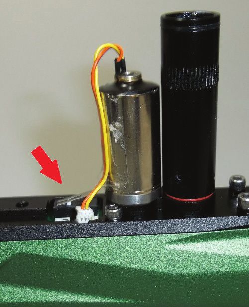
brand alkaline batteries is recommended for optimum performance. The 9-volt battery is located in the 4. BREAK BEAM EYES OPERATION
front Foregrip in front of the Trigger Guard. The battery is accessed by removing the front rubber Grip. The AXE uses a break beam eye system to determine the absence or presence of a paintball in the
breech for the purposes of reduced paint breakage and optimum rates of fire. When the break beam
Confirm that the marker is Off. Remove the two screws that secure the front rubber grip to the left- system is activated the marker will not fire unless the break beam system detects a paintball. The AXE
hand side of the Foregrip with a 5/64” hex wrench. Peel back the rubber grip to access the battery board is pre-programmed to activate the eye system each time the marker is powered up.
compartment underneath. If there is already a battery in the Foregrip, gently remove the battery, and
To turn the eyes OFF, ensure that there are no paintballs in the AXE breech or feed-neck, make sure
then connect a fresh 9-Volt battery into the compartment following the polarity markings for positive (+) the marker is switched On, and then tap the button once. A fast, flashing LED will indicate that the eye
and negative (-). (Fig 2-4) Then re-install the front rubber Grip and screw it securely into place. system has been deactivated.
To turn the eyes back ON, tap the button one time.
A slow consistent single blinking Green LED indicates that the eyes are ON with no ball in the breech
and a double blink LED indicates that there is a ball in the breech.
If the Break Beam Eye System malfunctions, the marker assumes there was a ball broken and the
Rate of Fire (ROF) is limited to 8.0 balls-per-second (bps) to prevent further ball breaks. The LED
indicator will flash slowly. Turn the Break Beam Eye System OFF to allow firing at Max
ROF cap setting. Break Beam Sensor Status is indicated by blinking frequency of the LED (See table
below for explanation). Color would be determined by battery level, as listed in the chart in Section 3.
BLINK FREQUENCY BREAK BEAM (BB) EYE STATUS
(FIG. 2-4)
SINGLE BLINK BB SENSOR SYSTEM ACTIVE, NO BALL IN BREECH
DOUBLE BLINK BB SENSOR SYSTEM ACTIVE, BALL IN BREECH
SWITCHING OFF YOUR AXE
FLASHING BB SENSOR SYSTEM HAS MALFUNCTIONED
Push and hold the button on the front Foregrip. After the button is held for 2 seconds, the LED will turn to
a solid RED color. Release button and the AXE will switch Off. FAST FLASHING BB SENSOR SYSTEM DEACTIVATED
4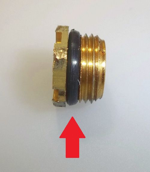
For optimal performance of the AXE eyes, keep the inside of the AXE breech clean and clear of              be above 300 feet per second, please check the fields specific velocity requirements as they vary.
broken paint, paint residue, or other debris. Although the eyes can be cleaned via cleaning the breech   − To Increase input pressure, turn Clockwise, making small adjustments while checking velocity
of the AXE marker, if the eye board needs to be accessed, please follow the steps outlined in the Main     using a chronograph.
Body Assembly section of this manual.                                                                    − To Decrease pressure, turn Counter-clockwise, making small adjustments while checking velocity
                                                                                                           using a chronograph. It is necessary to shoot the marker to decrease the pressure stored in the
TRIGGER PULL INDICATION                                                                                    marker.
If the Trigger is being pressed, the LED will display a dim Red LED which can be seen between blinks     − The regulator is designed to vent if it’s turned up too high. If this happens, degas your marker and
of the Eye Setting LED.                                                                                    turn the adjustment counter clockwise.

5. REGULATOR AND VELOCITY ADJUSTMENT                                                                     Fine Tuning the Velocity with Adjuster
The AXE utilizes a Regulator at the bottom of the Grip Frame that doubles as an Air Source Adapter       If further adjustment is needed to fine tune your markers velocity. When adjusting the velocity adjuster,
(ASA) for a standard threaded pre-set output compressed air system. This unique Regulator system         make small ¼ turn adjustments at a time.
channels air through a chamber in the Grip Frame eliminating the need for external hoses and fittings.
                                                                                                         − Turning the velocity adjuster clockwise will lower the velocity slightly, as it allows the poppet open less.
The Regulator controls the amount of air pressure going from your compressed air system into the
marker itself.                                                                                           − Turning the velocity adjuster counter clockwise will increase the velocity slightly, as it allows the
                                                                                                              poppet to open further. It is recommended that you don’t go above 2 full turns from all the way in
ADJUSTING THE VELOCITY
The Regulator output pressure and the Velocity Adjuster setting both affect and the Axe’s velocity.      Notes:
Your marker should be factory set to shoot about 275fps, but it will be necessary to adjust your Axe     • Always make regulator adjustments while using a paintball chronograph.
marker due to field rules and paintball size differences.                                                • Do not use CO2!!!
                                                                                                         • The Regulator should not be disassembled.
Setting the Velocity Adjuster                                                                            • The regulator is designed to vent at about 275psi.
− With marker degassed, turn the velocity adjuster all the way in until it stops using a 3/32” hex       • This marker was designed with safety and safety standards in mind. If you attempt to shoot
   wrench (Fig 5-1).                                                                                        paintballs at a higher velocity than established safety standards, the marker may not function
                                                                                                            properly.
                                                                                                         • If you attempt to operate the marker at extremely high velocities, the internals will not function
                                                                                                            properly.
                                                                                                         • This marker is not designed to shoot above the safety limits established by industry standards but
                                                                                                            under certain conditions it may. It is therefore important to check the velocity each time before
                                                                                                            playing with your AXE.

                                                                                                         6. SHOCKWAVE BOARD SETTINGS AND FUNCTIONS
                           (FIG. 5-1)                                                                    The electronic board features several modes and functions that are listed below. The board is located
                                                                                                         inside the front Foregrip of the marker. Before changing or adjusting any of the board functions,
                                                                                                         remove the propellant source from the AXE and install a barrel blocking device. The board inside
− Then turn the velocity adjuster counter-clockwise 1 full turn.
                                                                                                         your AXE features 4 firing modes and 6 adjustable functions. It uses a 3 color LED indicator on the
− This sets your velocity adjuster to the default setting of 1 turn.                                     backside of the front Foregrip to indicate functions and modes during programming

Adjusting Regulator Output Pressure                                                                      TOURNAMENT LOCK
− With the marker degassed, adjust the regulator adjustment screw using a 3/32” hex wrench so it’s       Tournament lock is a feature that prevents the marker from entering the Settings Mode while in the
   flush with the regulator cap. (Fig 5-2) This is the default setting.                                  field, to allow the marker to be tournament legal. See your tournament’s rule book for an explanation
                                                                                                         on what is required to lock your marker. Tournament Lock can be turned on/off by using the dip switch
                                                                                                         1 located on the inside of the Foregrip near the bottom of the circuit board. Flip dip switch #1 to the
                                                                                                         ON (UP when lying flat) position to activate the Tournament Lock. (Fig 6-1) When tournament lock is
                                                                                                         ON, Settings Mode cannot be activated.  See Section 7 for instructions to access the Foregrip.

                           (FIG. 5-2)

− Using the regulator lever, apply air into the marker.
− Use a paintball specific chronograph to adjust regulator to the desired velocity. Which should never                             (FIG. 6-1)

                                                                                                                                                                                                                    5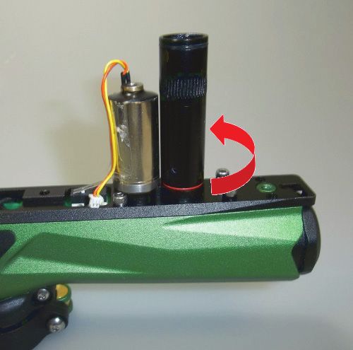
SETTINGS MODE                                                                                                     IMPORTANT: When the Firing Mode is changed it will also automatically modify the
The AXE must be Off and the Tournament Lock must be Off to begin managing the settings and                        corresponding Max Rate of Fire and ramping parameters that correspond to that mode. These
functions. To activate the marker in Settings Mode, press and hold the Trigger, then press and hold               settings may be changed after Firing Mode is selected
the button on the back side of the Foregrip. The LED will cycle through an array of colors to indicate
the Settings mode is active. You may now release the Trigger and the button. Once the LED is done
                                                                                                                    NUMBER
cycling you are ready to navigate through settings mode.                                                                              MODE
                                                                                                                    OF BLINKS
NAVIGATING THROUGH SETTINGS                                                                                              1         SEMI-AUTO
Once in Settings Mode, use the Trigger is used to navigate to the next setting, where the LED                            2            BURST
indicates which setting as listed in the chart below. Pressing and releasing the Trigger quickly will
                                                                                                                         3          RAMPING
navigate to the next setting.
                                                                                                                         4         FULL AUTO
The LED color/status will change accordingly.
                                                                                                                  Semi Auto: Marker will shoot 1 time for each time the Trigger is pulled.
Example: If currently in Firing Mode (solid Red), press and release the Trigger 3 times to get to                   Default: Max ROF = 15.0bps
De-Bounce (flashing Red).
                                                                                                                  Burst: Marker will shoot in semi-auto mode equal to the number of shots specified by the Ramp Start
              LED COLOR                    SETTING                                                                setting (see below for more information), then will go into a 3-shot burst at the Max ROF setting. If the
              SOLID RED                 FIRING MODE                                                               marker is not fired for 1 second, the marker will shoot semi-auto until Ramp Start
                                                                                                                  is again achieved.
             SOLID GREEN                   MAX ROF
                                                                                                                      Default: Max ROF = 12.0bps; Ramp Start = 3 shots
            SOLID AMBER                     DWELL
            FLASHING RED                 DE-BOUNCE                                                                Ramping: Marker will shoot in semi-auto mode equal to the number of shots specified by the Ramp
          FLASHING GREEN               BALL IN PLACE                                                              Start setting, and if the Ramp Sustain ROF (see below for more information) is achieved, the marker
                                                                                                                  will ramp up to the Max ROF setting. If the marker is not fired for 1 second, the marker will shoot semi-
         FLASHING AMBER    RAMP START
                                                                                                                  auto until ramping parameters are achieved.
        FAST FLASHING RED RAMP SUSTAIN                                                                                Default: Max ROF = 10.0bps; Ramp Start = 3 shots; Ramp Sustain = 6tps (Trigger pulls per second)

CHANGING SETTINGS
                                                                                                                  Full Auto: Marker will shoot in semi-auto mode equal to the number of shots specified by the Ramp
To change a setting, first navigate to the setting you would like to change by using the Trigger as
                                                                                                                  Start setting, then will go into full automatic mode as long as the Trigger is held down. If the marker is
described above. Once at the desired function, press and hold the Trigger for 2 seconds. The LED will
                                                                                                                  not fired for 1 second, the marker will then shoot semi-auto again until Ramp Start
then begin blinking to indicate the setting’s current value. Once the blinking stops, theMLED will turn
                                                                                                                  is achieved again.
off and you have a 3 second window to begin entering a new value. Press and release the Trigger the
                                                                                                                      Default: Max ROF=12.0bps; Ramp Start = 3 shots
number of times corresponding to the desired new setting value. After the desired number is reached,
release the Trigger and after 3 seconds the LED will cycle through an array of colors to indicate the
                                                                                                                  MAX RATE OF FIRE (ROF)
setting is saved. If you do not enter any Trigger pulls to modify a setting, the value remains the same.
                                                                                                                  - INDICATED BY SOLID GREEN LED
If you enter more than maximum amount of Trigger pulls for any setting, the value will become the
                                                                                                                  This setting controls the maximum number of paintball per second the marker is allowed to fire. The
maximum value for that setting. Power off the marker to exit the Settings Mode. Any setting that was
                                                                                                                  setting can be varied from 8 to 20 balls per second (bps) in 0.5bps intervals. Use the chart below to
modified will be stored and ready to use upon startup.
                                                                                                                  set the Max ROF.
                                                                                                                      Default: Max ROF = 15.0 bps
FIRING MODES
Indicated by a Solid Red LED
                                                                                                                  You must be in the Settings Mode to change the Max ROF, see above for instructions on how to
You must be in the Settings Mode to change Firing Modes, see above for instructions on how to enter
                                                                                                                  enter Settings Mode. After choosing Max ROF Mode (Solid Green), hold the Trigger to get into the
Settings Mode. After choosing Firing Modes (Solid Red), hold the Trigger, the LED will flash Red LED
                                                                                                                  Mode, the LED will flash GREEN LED blinks equal to the current setting, followed by a pause. Pull the
blinks equal to the current setting, followed by a pause. Pull the Trigger the number of times equal to
                                                                                                                  Trigger the number of times equal to your new desired setting (see chart below). Once done, the LED
your new desired setting (see chart below). Once done, the LED will cycle through an array of colors
                                                                                                                  will cycle through an array of colors to indicate the setting is saved and return to the Settings Mode.
to indicate the setting is saved and return to the Settings Mode. There are 4 firing modes available:
Semi Auto, Burst, Ramp, and Full Auto.

Note: All modes will perform 3 semi-auto safety shots prior to the activation of the mode, as required by ASTM.

                                                                                                                                                                                                                          6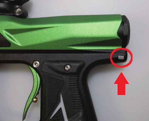
Example: 10 LED blinks = 12.5 BPS TRIGGER DE-BOUNCE
# LED BPS # LED BPS # LED BPS - WILL BE INDICATED BY A FLASHING RED LED
BLINKS VALUE BLINKS VALUE BLINKS VALUE Time in milliseconds the Trigger pull must be released before the next Trigger pull can be registered.
1 8 10 12.5 19 17 This eliminates electronic noise and vibrations (“Trigger Bounce”) that the board may wrongly interpret
2 8.5 11 13 20 17.5 as a Trigger action (Trigger pull) and fire the marker. A higher setting will reduce the bounce. A lower
3 9 12 13.5 21 18 setting will allow for more bounce. One blink corresponds to 1ms of De-Bounce time. De-Bounce is
4 9.5 13 14 22 18.5 adjustable from 1-15ms in 1.0ms increments.
5 10 14 14.5 23 19 Default: De-Bounce = 5.0 ms
6 10.5 15 15 24 19.5 You must be in the Settings Mode to change the De-Bounce Setting, see above for instructions on
7 11 16 15.5 25 20 how to enter Settings Mode. After choosing De-Bounce Setting (Flashing Red), hold the Trigger to
8 11.5 17 16 display the value, the LED will show flashing Red LED blinks equal to the current value,
9 12 18 16.5 followed by a pause. Pull the Trigger the number of times equal to your new desired setting, one pull
per desired setting equal to each millisecond. Once done, the LED will cycle through an array of colors
Starting in 2021
to indicate the setting is saved and return to the Settings Mode.
# of Blinks BPS Value # of Blinks BPS Value # of Blinks BPS Value
1 4.0 12 9.5 23 15.0
BALL IN PLACE (BIP) DELAY
2 4.5 13 10.0 24 15.5
- WILL BE INDICATED BY A FLASHING GREEN LED
3 5.0 14 10.5 25 16.0
Time in milliseconds the ball must stay in breech before it can be fired. Increase this setting for
4 5.5 15 11.0 26 16.5 slower feeding loaders to avoid chopping balls in the breech. Faster force feed loader systems
5 6.0 16 11.5 27 17.0 may allow for a lower setting to help achieve higher rates of fire. BIP Delay is adjustable from
6 6.5 17 12.0 28 17.5 1-40ms in 1.0ms increments.
7 7.0 18 12.5 29 18.0 Default: BIP Delay = 5.0ms
8 7.5 19 13.0 30 18.5
Note: If you are not using a force-feed loader, it is recommended that you use a higher BIP setting.
9 8.0 20 13.5 31 19.0
10 8.5 21 14.0 32 19.5 You must be in the Settings Mode to change the BIP Delay Setting, see above for instructions on how to
11 9.0 22 14.5 33 20.0 enter Settings Mode. After choosing BIP Delay (Flashing Green), hold the Trigger to get into the Mode,
the LED will show flashing Green LED blinks equal to the current setting, followed by a pause. Pull the
DWELL SETTING Trigger the number of times equal to your new desired setting, one pull per desired setting equal to each
- WILL BE INDICATED BY SOLID AMBER LED millisecond. Once done, the LED will cycle through an array of colors to indicate the setting is saved and
This setting controls the amount of time the solenoid valve is left open. A setting too high will waste return to the Settings Mode.
excess gas and affect efficiency. A setting too low will prevent marker from operating properly. It is not RAMP START
recommended to change this setting unless you are an experienced user. Dwell time is 3.0ms and is - INDICATED BY A FLASHING AMBER LED
increased in .5ms increments up to 10ms. Use the chart below to set the Dwell. This setting controls the amount of semi-automatic shots must be fired before ramping will start. If the
Default: Dwell = 8.0 ms marker is not fired for 1 second, the count will start over. Ramp Start is adjustable from 1-12 shots in 1
You must be in the Settings Mode to change the Dwell Setting, see above for instructions on how to shot increments. Default: Ramp Start = 3 Shots
enter Settings Mode. After choosing Dwell Setting (Solid Amber), hold the Trigger to get into the Mode,
You must be in the Settings Mode to change the Ramp Start Setting, see above for instructions on how
the LED will flash Amber LED blinks equal to the current setting, followed by a pause. Pull the Trigger
to enter Settings Mode. After choosing Ramp Start (Flashing Amber), hold the Trigger to get into the
the number of times equal to your new desired setting (see chart below). Once done, the LED will
Mode, the LED will show flashing Amber LED blinks equal to the current setting, followed by a pause.
cycle through an array of colors to indicate the setting is saved and return to the Settings Mode.
Pull the Trigger the number of times equal to your new desired setting, one pull per desired setting equal
to one shot. Once done, the LED will cycle through an array of colors to indicate the setting is saved and
# LED DWELL IN # LED DWELL IN return to the Settings Mode.
BLINKS MS BLINKS MS
RAMP SUSTAIN
1 3 9 7
- INDICATED BY A FAST FLASHING RED LED
2 3.5 10 7.5 This setting controls the amount of Trigger pulls per second (TPS) that must be achieved and
3 4 11 8 sustained for ramp to kick in. Ramp Sustain is adjustable from 1-12 Trigger-pulls-per-second (tps) in 1
4 4.5 12 8.5 tps increments.
5 5 13 9 Default: Ramp Sustain = 3 tps
6 5.5 14 9.5 You must be in the Settings Mode to change the Ramp Sustain Setting, see above for instructions on
7 6 15 10 how to enter Settings Mode. After choosing Ramp Sustain (Fast Flashing Red), hold the Trigger to get
8 6.5 into the Mode, the LED will show fast flashing Red LED blinks equal to the current setting, followed by
a pause. Pull the Trigger the number of times equal to your new desired setting, one pull per each
7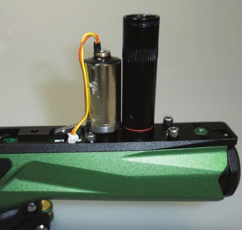
TPS. Once done, the LED will cycle through an array of colors to indicate the setting is saved and           REMOVAL, INSTALLATION AND CLEANING
return to the Settings Mode.                                                                                 OF BALL DETENTS AND EYES
                                                                                                             − Using a 5/64” hex wrench, insert hex
Note: This setting affects only Millennium/ Ramp Firing Mode.                                                  wrench into the screw hole of the Eye
                                                                                                               Cover and turn counter-clockwise. (Fig 7-1)
FACTORY RESET
The board has a feature that allows the user to reset all of the settings back to the stock configuration.
Tournament Lock must be off to perform factory reset. The following steps are required to perform a                                                                                (FIG. 7-1)
Factory Reset:
1. With board Off, turn marker On in settings mode.                                                          − Using the end of the hex wrench, carefully pry the Ball Detent from the Body
2. Press and hold the button on the Foregrip, then press and hold the Trigger so that both the button        − Clean the detent with a damp cloth or with warm water if covered with paint
   and Trigger are being held simultaneously (Note: button must be pressed first).                           − Place the Detent back into its socket within the Body
3. Hold both the button and Trigger for approximately 5-6 seconds. The LED will then start alternating       − Using the end of the hex wrench, carefully pry the Eye from the Body using care not to damage the
   green and red. Now release the button and Trigger.                                                          eye wires
4. When the board is done resetting the board will turn off.                                                 − Clean the Eye with a dry cloth
                                                                                                             − Carefully replace the Eye into the socket in the Body
TRIGGER ADJUSTMENT                                                                                           − Install the Eye Cover making sure the Eye is safely in its socket. Tighten the screw with a 5/64” hex
There are five adjustments that can be made on the on the trigger (Fig 6-2). Use the 5/64” hex wrench          wrench.
to make any desired adjustments:                                                                             Note: Be careful not to lose the detents as they are small and unattached.
A. Forward Travel – This adjusts the position of the trigger
when not being fired                                                                                         REMOVAL OF BOLT AND BOLT GUIDE
- Turning the adjustment screws “in” or clockwise will                                                       ASSEMBLY
decrease the trigger length of travel                                                                        − Press and hold the Bolt Guide Release
B. Stop – This adjusts the farthest position the trigger will                                                  Button, located on the left-side of the
travel when depressed                                                                                          rear of the Grip Frame (Fig 7-2)
- Turning the adjustment screws “in” or clockwise will
decrease the travel of the trigger by having the trigger stop
sooner
                                                                                                                                                                              (FIG. 7-2)
C. Activation Point – This adjusts the position where the
trigger pull registers a shot by activating the trigger switch    (FIG. 6-2)

- Turning the adjustment screws “in” or clockwise will decrease                                              − While holding the button, grip and pull the
the travel of the trigger needed before the AXE registers a shot                                               Bolt Guide free of the Body removing the
D. Magnetic Tension – This affects how “hard” the pull of the trigger is                                       bolt system (Fig 7-3)
- Turning the adjustment screws “in” or clockwise will increase the force needed to pull the trigger

7. ASSEMBLY/DISASSEMBLY AND MAINTENANCE
CAUTION: Before attempting to perform any maintenance operations or any marker disassembly,
make sure that all paintballs and propellant sources have been removed from the marker and that the
Regulator gauge reads 0 psi. Install a barrel blocking device, and that the power is Off.                                                                                     (FIG. 7-3)

GENERAL MAINTENANCE                                                                                          MAINTENANCE OF BOLT AND BOLT GUIDE ASSEMBLY
Keep your AXE clean and lubricated to eliminate the friction that would prevent reliable operation. Clean    - Inspect the O-rings on both the bolt and Bolt Guide for any wear or damage. Replace damaged or
and lube the marker before each use, and do not put it away dirty. Only use oils designed for paintball        worn O-rings if necessary. (Fig 7-4)
and they may only be used on the regulator. DO NOT USE OIL ON THE BOLT SYSTEM. Do NOT use                    - Lubricate all O-rings on Bolt and Bolt Guide with Empire marker grease, the supplied grease or a
petroleum-based lubricants in the lubrication of this marker. Under any circumstances, do NOT use a            paintball specific marker grease. Only a small amount is needed.
solvent-based lubricant. Teflon or silicone (Non-spray only) lubricants designed for use on O-rings may
be used for lubrication for the bolt area only of the main housing. Only use Paintball specific marker
grease, such as Empire Vitamin E grease. The following maintenance procedures described below
should be performed before each day of use or every 20,000 shots, whichever comes first.

                                                                                                                                         (FIG. 7-4)

                                                                                                                                                                                                                  8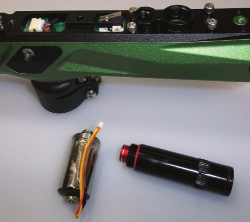
MAINTENANCE OF POPPET                                                                                                                               -   Locate the two screws near the corners of the Trigger
- Use a 3/32” hex wrench and insert it into the back of the Bolt Guide Cap. Turn counter-clockwise                                                      Guard, one on each side of the AXE. Use a 5/64” hex
  until Bolt Guide Cap is completely removed. (Fig 7-5)                                                                                                 wrench to remove those screws.
- Inspect and lubricate Bolt Guide Cap O-ring.                                                                                                      -   There are three screws located on the front of the
- Carefully insert a non-metallic object (like the back of a pen) into the front of the Bolt Guide. Push                                                Foregrip. One in the center at the very top and two at the
  Poppet Assembly out the back of the Bolt Guide. (Spring may fall out of Bolt Guide) (Fig 7-6)                                                         bottom. Remove them using a 3/32” hex wrench
- Lubricate the Poppet O-ring, which is the most important O-ring used in the AXE and should be                                                     -   Carefully unplug the Battery Harness from the board. Do
  maintained often.                                                                                                                                     not pull the wires or they may break off the battery contacts.
                                                                                                                                                    -   The Foregrip assembly will now lift free of the Grip
                                                                                                                                                                                                                                  (FIG. 7-9)
                                                                                                                                                        Frame. (Fig 7-9)

                                                                                                                                                    INSTALLATION OF FOREGRIP
                                                                                                                                                    To reinstall the Foregrip Assembly onto the Grip Frame and Body.
             (FIG. 7-5)                                                         (FIG. 7-6)                                                          - Connect the Battery Harness from the Foregrip into the Board on the Grip Frame.
                                                                                                                                                    - Slide the Foregrip assembly back over the board and onto the Grip Frame, aligning the screw holes.
REPLACING THE POPPET SEAL                                                                                                                           - Install the three front screws using the 3/32” hex wrench and the two side screws using the 5/64”
If there is a slight air leak evident coming through the bolt area, the Poppet Seal may be worn and                                                    hex wrench.
need to be replaced. With the Poppet removed, grab the Poppet Seal with pliers and unscrew the                                                      - Reinstall the rubber Grip using the four screws and a 5/64” hex wrench.
Poppet by hand from the Poppet Seal. Do not grab the Poppet with pliers or put in a vice as it may
                                                                                                                                                    Note: If not installed correctly, you might damage the Circuit Board!
damage the brass. Install the new Poppet Seal by hand. Once tightened by hand, the Poppet will hold
the Poppet Seal in place and it should not come apart during operation.                                                                             REMOVAL OF GRIP FRAME
                                                                                                                                                    - Using a 5/64” hex wrench, loosen and remove the four screws holding the rubber Grip onto the
REINSTALLATION OF POPPET, POPPET SPRING AND BOLT GUIDE CAP                                                                                            Foregrip.
- Place Poppet assembly into the back of the Bolt                                                                                                   - Peel back the rubber Foregrip and remove the top screw at the front of the Foregrip using a 3/32”
  Guide and gently push forward. If installed                                                                                                         hex wrench.
  properly the Poppet assembly will be all the way                                                                                                  - Using a 3/32” hex wrench, remove the two Grip Frame screws by turning counter-clockwise. (Fig 7-10)
  forward resting on the Bolt Guide internal face.                                                                                                  - The forward Grip Frame screw is
  Make sure the Poppet spring is seated straight in                                                                                                   located within the Trigger Guard
  the back of the Poppet. (Fig 7-7)                                                                                                                 - The rearward screw is located at the
- Using the 3/32” hex wrench, screw the Bolt Guide                                                                                                    back of the marker, below the Bolt
  Cap clockwise back into the Bolt Guide. Screw         (FIG. 7-7)                                                                                    Guide
  the Bolt guide cap all the way in, then turn out                                                                                                  - Gently pull down the frame from Body.
  1/2 turn. Further adjustment over a chronograph will be needed to achieve desired velocity.

REINSTALLATION OF MAIN SPRING, BOLT AND BOLT GUIDE ASSEMBLY
Slide main spring onto bolt, and then bolt onto
Bolt Guide, so it is one assembly. You will                                                                                                                                                                         (FIG. 7-10)
notice, one end of the spring is smaller and
will lock onto the bolt. (Fig 7-8) Insert assembly
into the back of Body.                                                                                                                              INSTALLATION OF GRIP FRAME
                                                                                                                                                    - Inspect the Air Transfer Tube O-ring and lightly grease. As you install the Grip Frame, make sure
                                                                                                                                                       the Solenoid wires do not get pinched and hold the Trigger in to prevent the Trigger activation lever
                                                                       (FIG. 7-8)
                                                                                                                                                       from getting damaged. Gently push Grip Frame back on and line up the air transfer tubes.
                                                                                                                                                    - When the Grip Frame is back on, use the 3/32” hex wrench and tighten the (2) Grip Frame screws
Notes:                                                                                                                                                 clockwise.
- On the bottom side of the Bolt Guide there is a small alignment pin at the rear of Bolt Guide. This must line up with the alignment hole.         - Do not over tighten.
- Holding the bolt assembly tight into the back of the Body with one hand, re-install the rear frame screw and tighten using the 1/8” hex wrench.

REMOVAL OF FOREGRIP ASSEMBLY
Note: Be careful with the Battery wires when removing the Foregrip.

-   Using a 5/64” hex wrench, loosen and remove the four screws holding the rubber Grip onto the Foregrip.
-   There are five screws that hold the Foregrip to the Grip Frame and Transfer Plate.
                                                                                                                                                                                                                                                          9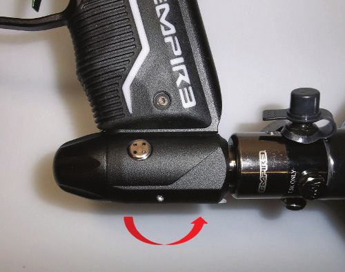
REMOVAL OF REGULATOR                                                                                          Note: Be careful not to lose the Check Valve (air restrictor). The Check Valve is a small plastic piece located between the Body and air
                                                                                                              transfer plate.
- Remove the four screws that hold the rear
  Grip to the Grip Frame using a 5/64” hex
                                                                                                              INSTALLATION OF AIR TRANSFER PLATE
  wrench.
                                                                                                              - It is recommended that a small amount of Empire marker grease or paintball marker specific
- Remove the Air Transfer tube by unscrewing
                                                                                                                 grease is applied to the Air Transfer Gasket before the Air Transfer Plate is reattached.
  it counter-clockwise. Be careful not to lose the
                                                                                                              - Also make sure the Check Valve is in the Body, as seen in the picture above.
  female Air Transfer Tube bottom O-ring, which
                                                                                                              - Place Transfer Plate back on Body and evenly tighten all 7 screws using a 3/32” hex wrench.
  sits on the bottom of the tube.
                                                        (FIG. 7-11)                                           - Screw the Solenoid into the Air Transfer Plate, tightening in a clockwise direction.
- Loosen the two Regulator Mount screws
                                                                                                              - Repeat with the male Air Transfer Tube
  located on the inside of the Grip Frame
                                                                                                              - Plug the Solenoid back into the sensor board.
  (on each side of the transfer tube) with a 3/32” hex wrench by turning them counter clockwise. (Fig 7-11)
- The Regulator can now be slid forward and off the Grip Frame.                                               REMOVAL AND CLEANING OF SENSOR BOARD
                                                                                                              - Remove Foregrip, Grip Frame, and Air Transfer Plate as described in the steps above.
INSTALLATION OF REGULATOR ASSEMBLY
                                                                                                              - Gently remove the Sensor Board from the Body, using caution to prevent bending the Eyes.
- Slide Regulator along the T-rail of the Grip Frame, orientated for the ASA opening is facing the rear
                                                                                                              - Once the board is removed, use a dry cloth to clean the Eye sensors.
   of the marker.
                                                                                                              - If paint is on the board, use a dry cloth to wipe paint off the board.
- Install the two Regulator Mount screws located on the inside of the Grip Frame (on each side of
                                                                                                              - Rubbing alcohol may be used if deep cleaning is needed. Do not use water on any electronics.
   the transfer tube) with a 3/32” hex wrench by turning them clockwise. Do not over tighten.
- Make sure the female Air Transfer Tube O-ring is on the bottom of the Air Tube, add grease if 		            INSTALLATION OF SENSOR BOARD
   necessary.                                                                                                 - When installing board back in main Body, be careful that the sensors line up correctly.
- Install the Air Transfer tube be screwing it clockwise. Do NOT torque, hand tighten only.                   - The board should drop into the Body very easily. Do NOT force the Sensor Board into the Body.
- Install the four screws that hold the rear Grip to the Grip Frame using a 5/64” hex wrench.                 - Once in place, install the Air Transfer Plate and other components as described in this manual.

REMOVAL OF AIR TRANSFER PLATE                                                                                 8. EMPIRE REGULATOR SERVICE GUIDE
- Remove the Foregrip and Grip Frame using instructions shown earlier in this manual.                         WARNING: Remember to remove all gas and ensure marker is discharged before servicing Regulator.
- Carefully unplug the solenoid from the Sensor board.                                                        WARNING: The following service should be performed by an experienced user. If you are not comfortable
- Remove the male Air Transfer Tube assembly from the Air Transfer Plate by unscrewing it counter             performing the steps below, please contact Empire customer service at www.paintballsolutions.com
  clockwise. (Fig 7-12)
- Remove the Solenoid from the Air Transfer Plate by unscrewing it counter-clockwise. (Fig 7-13)              For ASA/Regulator service you will need the following tools: 3/32” hex wrench, needle nose pliers,
- Using a 3/32” hex wrench, remove all of the Air Transfer Plate screws (7 total). (Fig 7-14)                 O-ring pick, 1/2in socket or nut driver, 3mm nut driver, Dow 33 type grease
- Once the screws are removed the Air Transfer Plate will then lift off.                                      1. Grasp the Regulator Front Cap and unscrew counter-clockwise. If it does not turn easily, use a
                                                                                                                  3/32 hex wrench in hole on front cap of the regulator and unscrew the front cap (Fig 8-1).
                                         (FIG. 7-12)                       (FIG. 7-13)
                                                                                                                  The Main Spring and Spring Plate will be sitting loose in the Front Cap. Be sure not to lose these
                                                                                                                  parts (Fig 8-2).

                                                                                                                                                 (FIG. 8-1)                                 (FIG. 8-2)

                                                                                          (FIG. 7-14)         2.   Flip the On/Off Lever forward to Off position. Insert the 1/2in. hex socket into open side of Regulator
                                                                                                                   and unscrew the brass nut from the Regulator in the counter-clockwise direction (Fig 8-3).
                                                                                                              3.   Inspect the O-ring on the
                                                                                                                   brass nut and replace if
                                                                                                                   damaged (Fig 8-4)

                                                                                                                                                              (FIG. 8-3)                                 (FIG. 8-4)

                                                                                                                                                                                                                                                    10
4. Use a pair of pliers to remove the tank depression pin from the Pin/Seal Retainer in the tank side 9. Once the silver Piston and washer is removed, insert a 3/32” hex wrench into the tank side of the
of the Regulator. Be sure to grab the pin by its smaller section, near the tip. Inspect O-ring on the Regulator to push the silver piston through the front of the Regulator as seen in (Fig 8-12)
inside of the pin retainer and replace if necessary (Fig 8-5). 10. Insert a 3/32” hex wrench into the silver cap on side of Regulator to unscrew filter retainer cap.
5. Use a 3/32” hex wrench to unscrew the Lever Retaining Screw (Fig 8-6). The Lever is under The filter will fall out onto the cap once removed. Inspect the O-ring on filter cap and replace if
spring pressure, so you may have to push the Lever down slightly to remove the screw. Once the needed. (Fig 8-13)
screw is removed, the Lever will fall out and the Pin Depression Ramp with Spring will fall from the
bottom of the Regulator (Fig 8-7).
(FIG. 8-12) (FIG. 8-13)
11. Proceed to clean the inside of the Regulator and the removed parts with a clean cloth or cotton swab.
(FIG. 8-5) (FIG. 8-6) (FIG. 8-7)
REASSEMBLY
6. Insert the 3/32” hex wrench into the bottom of the Regulator where the Pin Depression Ramp was 1. Once clean, apply a liberal amount
removed from. Use the hex wrench to unseat the Pin/Seal Retainer by pushing it towards the tank of Dow 33 or equivalent grease to
side (rear) of the Regulator (Fig 8-8). Once unseated, remove the hex wrench and turn the tank the two O-rings on the brass Piston
side opening down to allow Pin/Seal Retainer to fall into your hand. Inspect the outer O-rings of as shown in (Fig 8-14,) making sure
the pin/seal retainer for damage and replace if needed (Fig 8-9). to fill the grooves that the O-rings sit
in with grease. (FIG. 8-14) (FIG. 8-15)
2. Place the secondary spring into the
deeper side of the brass piston and insert the assembly into the
front of the Regulator (Fig 8-15).
3. Place the silver piston into the 3mm nut driver and the washer onto
the silver piston with the curved side of the washer facing the head
of the piston (Fig 8-16). Insert the assembly into the tank side of
(FIG. 8-8) (FIG. 8-9) Regulator and screw silver piston into brass piston until snug. DO
NOT OVER TIGHTEN the silver piston. Only tighten until turning
(FIG. 8-16)
7. Insert the 3mm nut driver into the tank side of the Regulator onto the silver Piston. On the silver piston spins brass piston as well.
opposite side of the Regulator (front), place the O-ring pick in the small hole on the brass piston 4. Place filter in filter cap and screw the assembly into filter area using 3/32 hex wrench (Fig 8-17).
as shown in (Fig 8-10) Hold the brass Piston stationary and unscrew the silver Piston. Once fully 5. Insert pin/seal retainer in orientation shown in (Fig 8-18) into tank side of Regulator ensuring oval
unscrewed, turn the tank opening side down and allow the washer and silver piston to come out slot in the pin/seal retainer is lined up with bottom slot on Regulator.
on the 3mm nut driver as shown in (Fig 8-11). 6. Insert the 3/32” hex wrench into bottom slot of Regulator and push the Pin/Seal Retainer towards
front of Regulator until the slot on the Regulator lines up with the slot on the seal retainer (Fig 8-19).
(FIG. 8-10) (FIG. 8-11)
(FIG. 8-17) (FIG. 8-18) (FIG. 8-19)
8. If the Piston and washer don’t fall out easily, use pliers to grab the Piston by the head and lift it
from the Regulator body. Then use an O-ring pick to loosen the washer, carefully, while not 7. Insert the Pin Depression Ramp and Spring back into the
damaging the washer. Note the washer is semi-transparent and may be hard to see. If the washer bottom of Regulator with the ramp facing toward tank side of
is damaged or the Regulator was having over pressurization problems the washer should be Regulator (Fig 8-20). The ramp should fall into place easily
replaced. and if not, ensure the slots on the Regulator and Pin/Seal
Retainer line up on all sides.
(FIG. 8-20)
118. Place lever on top of pin ramp in off position and install lever retainer screw using 3/32 hex
wrench (Fig 8-21).
9. Apply a small amount of Dow33 grease to the large part of the tank depression pin. Use pliers to
place the tank depression pin back into the Pin/Seal Retainer, being careful to only grip the small
end of the pin with the pliers. (Fig 8-22).
10. Use the ½” socket to reinstall the brass nut into the tank side of the Regulator (Fig 8-23).
11. Place silver washer in Regulator front cap as shown in Figure 8-24. Place main spring on top of
(FIG. 9-4) (FIG. 9-5) (FIG. 9-6)
washer and screw front cap onto front of Regulator. Only hand tightening is needed (Fig 8-25).
WARNING: Before applying air to marker unscrew Regulator adjustment screw to set pressure 7. Use a Q-tip or clean cloth to clean the piston and the cavity that holds the piston. Also clean the
to zero as pressures may have changed during service. rubber seals on both the top and bottom of the piston (Fig 9-7).
8. Once the solenoid cavity and piston have been cleaned, re-insert the piston into the cavity as
orientated in (Fig 9-8). The solenoid piston doesn’t require lubrication, though a very light coat of
paintball marker oil may be applied to the silver area of the piston if desired.
9. Replace the solenoid cap and the 3 screws that secure the cap in place (Fig 9-9). Do NOT over
tighten the screws.
10. Screw the solenoid back into air transfer plate and plug the wire back into sensor board (Fig 9-10).
11. Solenoid maintenance is now complete.
(FIG. 8-21) (FIG. 8-22) (FIG. 8-23)
(FIG. 9-7) (FIG. 9-8) (FIG. 9-9) (FIG. 9-10)
(FIG. 8-24) (FIG. 8-25)
WARNING: Solenoid may be in open position after service. Before gassing up marker, turn marker on,
9. SOLENOID SERVICE GUIDE turn eyes off and pull trigger several times to close solenoid
1. Unplug the solenoid from the sensor board (Figure 9-1).
2. Unscrew the solenoid from air transfer plate (counter-clockwise) and set the marker off to the side (Fig 9-2). 10. STORAGE AND TRANSPORTATION
3. Inspect each O-ring at the bottom of solenoid threads (labeled A) and the top of solenoid (labeled - Your AXE must be clear of all paint and propellant when not being used.
B) for damage, replace as necessary (Fig 9-3). - Make sure the AXE marker is Off: Push the Power button and hold for over 2 seconds until the
LED light changes to Red
- Put the barrel blocking device in its place. Make sure the marker is clean.
- Store your AXE in a clean, cool, dry place.
- Keep your AXE away from unauthorized and unsafe users.
- It may be a good idea to remove the battery when storing your marker to prevent unauthorized
use and to extend battery life.
(FIG. 9-1) (FIG. 9-2) (FIG. 9-3) Your AXE must be clear of all paint and any source of propellant during transportation to and from the
playing field. Keep your barrel blocking device in place. Keep the AXE Marker switched Off. Protect
your marker from excessive heat during transportation. Observe and obey all local, state and federal
4. Remove the 3 small screws on the top of the solenoid using a 1/16 hex wrench or small Phillips laws concerning the transportation of paintball markers. For information concerning any of the laws in
head screw driver depending on the screw head (Fig 9-4). your area, contact your nearby law enforcement agency. If you must ship your AXE for any reason, the
5. Lift the top cap off the solenoid to expose the solenoid piston. Be careful not to lose the small box in which you purchased the marker should be used to protect your marker against rough handling
O-ring at the top of the solenoid, it may be stuck to the top cap (labeled A in Fig 9-5). If O-ring is during transport.
damaged, replace it.
6. Lift the piston from the solenoid (Fig 9-6). Never ship filled pressurized gas (HPA) cylinders!
IMPORTANT: Never carry your AXE uncased when not on a playing field. The non-playing
WARNING: If you are not comfortable performing this maintenance please contact Empire
public and law enforcement personnel may not be able to distinguish between a paintball
technical support by going to www.paintballsolutions.com marker and firearm. For your own safety and to protect the image of the sport, always carry
your AXE in a suitable marker case or in the box in which it was shipped.
1211. TROUBLESHOOTING GUIDE
Marker does not turn On Battery may not be fresh If you have tried several different batteries, check to make sure the
battery harness is plugged in to the board properly. If it is, unplug the
battery from the harness, press and hold the power button for 15sec
then release. Plug the battery back in and try again.
Board may have moisture damage The circuit board is protected with a moisture resistant coating but
occasionally prolonged exposure to moisture can cause a malfunc-
tion. If the marker was used in wet conditions unplug the battery
and remove both circuit board from marker to allow them to dry for at
least 24 hours then try turning it on again.
Marker does not fire/cycle Marker may not be turned on Check screen on rear of foregrip. OLED screen should be on when
marker is turned on.
Paintballs may not be fed into breech The anti-chop eye system prevents the marker from firing unless a
ball is present. When the eyes detect a ball the eye symbol on the
screen will have a filled circle in the middle. Never put anything
other than a paintball down the feedneck of the AXE. Check that the
bolt is fully returning and if not service you may need to change bolt
tip, small bolt guide O-rings and/or the bolt O-rings. Check that there
is a proper connection between the sensor board and main board.
Check for damage to the main board pins near the tip of the foregrip.
Trigger may need to be adjusted. The trigger indication arrow takes place of the tournament lock
symbol when the trigger is activated. If the trigger is being pressed
the arrow will point down, and point up if the trigger is released. If
it is not that way, then the trigger may need to be adjusted. See the
“Trigger Adjustments” section earlier in the manual. Check that there
is a proper connection between the sensor board and main board.
Check for damage to the main board pins near the tip of the foregrip.
Solenoid may not be connected Remove air source and paintball before disassembling the marker. If
your remove the grip frame you should be able to verify the solenoid
is plugged into the AXE sensor board.
Multiple paintballs fired from only one shot Ball detents may be torn or missing Remove the eye cover to check the condition of the ball detents. If
damaged or bent permanently replace one or both of them.
Marker is Breaking paintballs in the breech Ball detents may be torn or missing Remove the eye cover to check the condition of the ball detents. If
damaged or bent permanently replace one or both of them.
Eyes may be dirty Clean the eyes as described earlier in the manual. If the eyes are
dirty the eye symbol on the screen with have a big X in the middle
after the marker is fired.
Bolt tip may be bad A bad bolt tip may allow air to escape up the feedneck causing
breakage. This symptom is commonly known as “Blowback”
Bolt guide or Bolt O-rings may be bad Bad bolt or small bolt guide O-rings may allow air to escape up the
feedneck causing breakage. This symptom is commonly known
as "Blowback". Make sure these O-ring are in good condition and
properly lubricated. Replace if necessary.
Marker is shooting slower than set ROF Eyes may be dirty When the eyes are dirty the ROF is limited to 8bps to prevent
excessive ball breakage. Clean the eyes as described earlier in the
manual. If the eyes are dirty the eye symbol on the screen with have
a big X in the middle after the marker is fired.
13Velocity is Low/Inconsistent or velocity drops during rapid fire Poppet O-ring may be damaged or not properly lubricated See general maintenance section earlier in the manual to see how to
properly check and lubricate poppet O-ring.
Bolt guide or Bolt O-rings may be bad/may not be lubricated Bolt should stay on bolt guide when turned bolt side down and shak-
en. If bolt falls off replace 3 small bolt guide O-rings. Check bolt and
bolt guide O-rings for damage. Assure these O-rings are properly
lubricated according to general maintenance section of this manual.
Possible issue with marker pressure Pressure should be set to around 200psi. If pressure drops during
rapid fire and doesn’t recover to set pressure between each shot
try screwing in tank all the way or try a different tank. If switching
tank doesn't help the regulator/ASA may need to be serviced. See
Regulator maintenance guide in the manual
Velocity of first shot is higher than rest of string Possible issue with marker pressure Pressure should be set to around 200psi. If pressure rises above set
pressure quickly after a shot the regulator may need service. See
Regulator Maintenance Guide in this manual.
Marker contnues to fire when trigger is not being pulled Trigger may be adjusted too short If trigger is adjusted too short it could cause undesired activations on
the switch. See Trigger adjustments section earlier in the manual to
make trigger longer.
Solenoid doesn’t click Battery may not be fresh Try a new battery and make sure high quality Alkaline 9V battery.
Solenoid may be dirty and is sticking See solenoid cleaning in the maintenance section earlier in the manual.
Marker continues to fire when trigger is not being pulled Trigger may be adjusted too short If trigger is adjusted too short it could cause undesired activations on
the switch. See Trigger adjustments section earlier in the manual to
make trigger longer.
Trigger de-bounce may need to be increased The circuit board has settings called pull de-bounce and release
de-bounce that prevent accidental trigger swatch activations. In-
creasing these settings may fix this issue. See Board settings and
Functions section earlier in the manual to see how to adjust this.
Large gushing leak out of barrel/breech Solenoid may need to be reset The solenoid may occasionally stick open from being dirty, exces-
sive shock or loss of power in which case it needs to be reset. To
reset solenoid remove air source turn marker on, turn the eyes off
pressing and hold if up direction, press trigger multiple times you
should hear solenoid clicking. If solenoid doesn't click see "Solenoid
doesn't click" section in troubleshooting guide.
Small leak down the barrel The poppet seal may be dirty or damaged The poppet seal may be dirty or damaged
The bolt guide is dirty or damaged Screw VTry cleaning poppet seal and bolt guide area with a tip. If
this doesn’t work your bolt guide may be damaged where the poppet
seals and therefore needs to be replaced.
Front large bolt guide 0-ring is damaged Replace O-ring
Constant leak inside grip frame Eyes may be dirty Multiple causes Multiple seals or parts could cause a leak inside grip frame. Check
and replace seals if necessary for each possible cause. Possible
causes include: Solenoid Gasket, Solenoid, Large bolt guide O-rings,
O-rings on air transfer tubes,
Leak from back cap/velocity adjuster Velocity adjuster could be unscrewed too far Screw Velocity adjuster back in.
Air transfer O-ring may be damaged Change bottom air transfer O-ring.
Leak from bottom of regulator ASA where lever is Regulator pressure is set too high This cap contains the over pressure protection valve (OPP valve).
It will leak it the pressure is approximately 250psi or higher. If it
leaks at less than 200psi it may need service which would require a
certified tech.
14You can also read